★ TRUSTED BY 321,897+ PROFESSIONALS WORLDWIDE
🏒
Trusted Business
Verified & Licensed
πŸ›‘οΈ
Virus Free Files
100% Safe Downloads
πŸ”’
Secure Payment
SSL Protected
⚑
Instant Delivery
Available Immediately
Sale!

Hitachi EH4000AC II Rigid Dump Truck Workshop Manual – Part No. W8R7-E-00

Original price was: $39.95.Current price is: $24.95.

Genuine Hitachi EH4000AC II Rigid Dump Truck Workshop Manual (Part No. W8R7-E-00), 760 pages covering disassembly, assembly, torque specs and component removal/installation for the full machine. Instant PDF download.

⚑
Instant PDF Download
Available immediately
πŸ’Ύ
Save to Your Device
Download & keep forever
πŸ›‘οΈ
Antivirus Scanned
100% virus-free
🌍
Trusted Worldwide
175,000+ customers

Description

Hitachi EH4000AC II Rigid Dump Truck Workshop Manual

This Hitachi EH4000AC II Rigid Dump Truck Workshop Manual is the complete 760-page shop reference (Part No. W8R7-E-00) covering hands-on disassembly, assembly, removal and installation procedures for the EH4000AC II rigid-frame dump truck. It is the Workshop Manual volume of Hitachi’s three-part service set, focused entirely on physical repair work rather than electrical theory or fault-code troubleshooting.

  • Manual Type: Workshop (Service/Repair) Manual
  • Brand / Model: Hitachi EH4000AC II Rigid Dump Truck
  • Document Number: W8R7-E-00
  • Language: English
  • Page Count: 760 pages
  • File Format: PDF

IMAGES PREVIEW

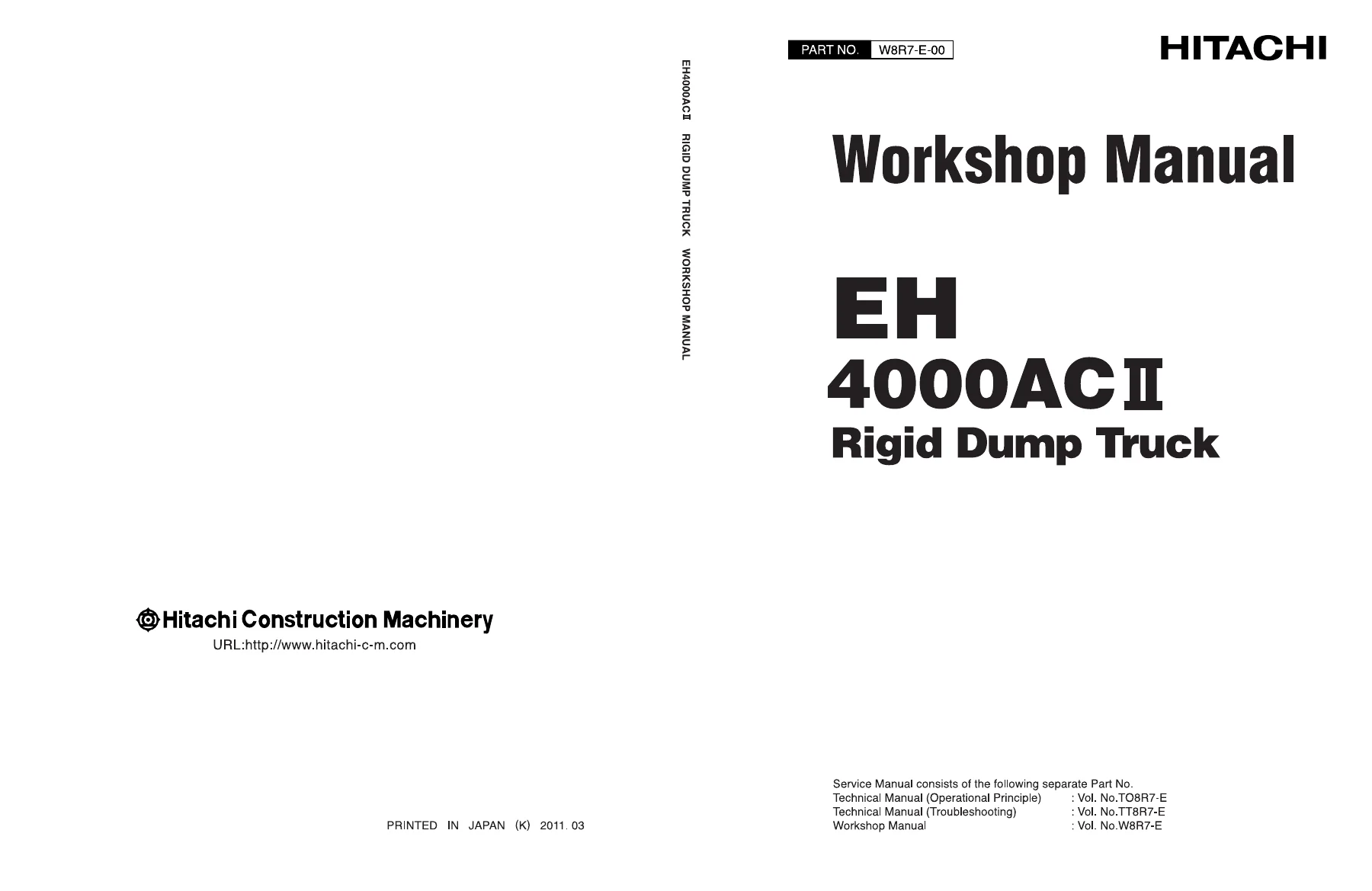
Hitachi EH4000AC II Rigid Dump Truck Workshop Manual - Part No. W8R7-E-00 β€” PDF page 1 preview
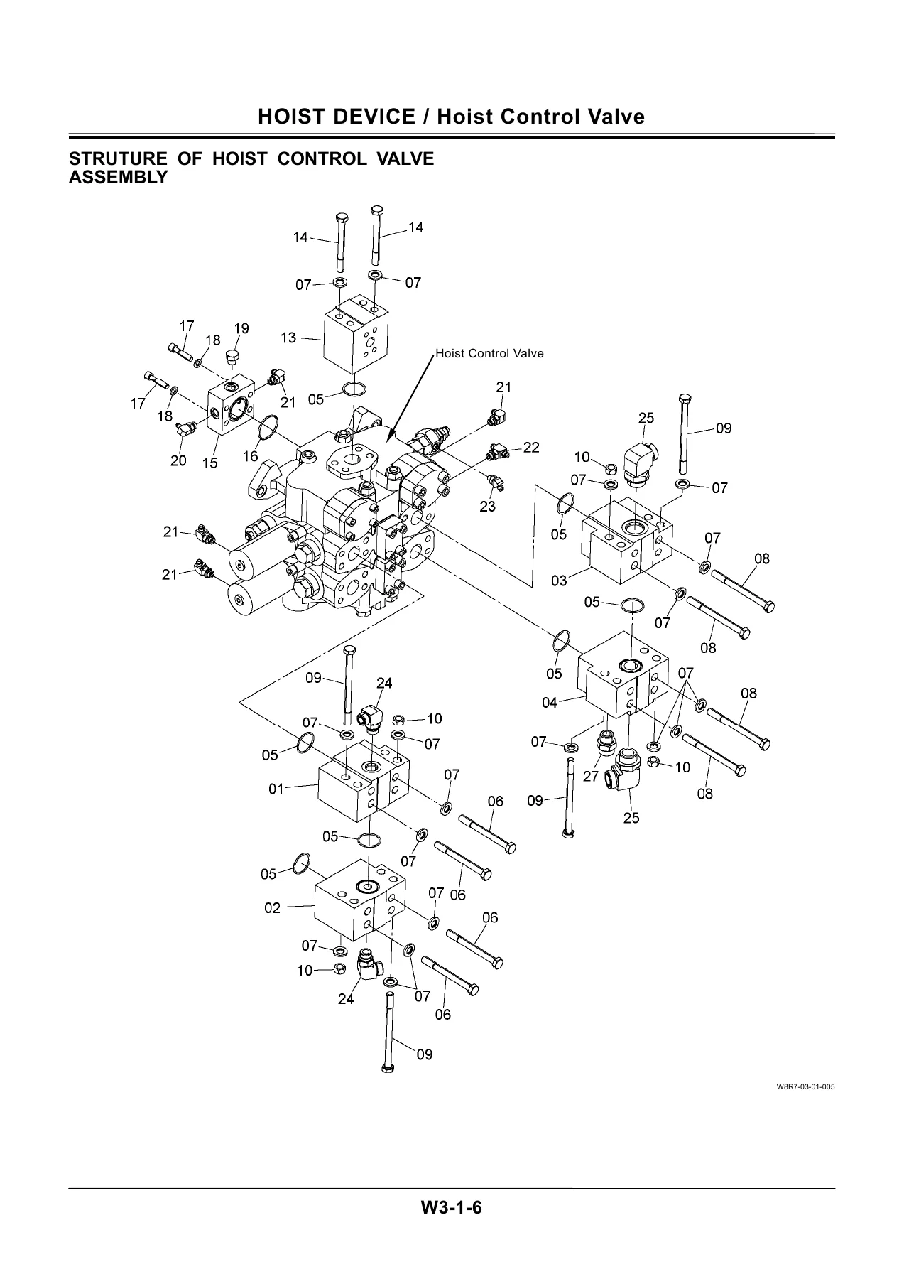
Hitachi EH4000AC II Rigid Dump Truck Workshop Manual - Part No. W8R7-E-00 β€” PDF page 568 preview
Hitachi EH4000AC II Rigid Dump Truck Workshop Manual - Part No. W8R7-E-00 β€” PDF page 754 preview

Chapters Covered

  • Section 1 General – Precautions for Disassembling and Assembling, Maintenance Standard Terminology
  • Section 1 General – Tightening Torque Specifications, Torque Chart, Piping Joint
  • Section 1 General – Periodic Replacement of Parts
  • Section 2 Body – Cab
  • Section 2 Body – Engine / Alternator
  • Section 2 Body – Pump Device
  • Section 2 Body – Driveline
  • Section 2 Body – Front Axle
  • Section 2 Body – Tire / Rim / Air Pressure
  • Section 2 Body – Front Brake
  • Section 2 Body – Brake Valve
  • Section 2 Body – Brake Accumulator
  • Section 2 Body – Steering System
  • Section 2 Body – Frame Suspension Cylinder
  • Section 3 Hoist Device – Hoist Control Valve
  • Section 3 Hoist Device – 4-Unit Proportional Control Solenoid Valve
  • Section 3 Hoist Device – Hoist Cylinder
  • Section 3 Hoist Device – Dump Body
  • Section 4 AC Drive Control Device – Control Cabinet
  • Section 4 AC Drive Control Device – Grid Box
  • Section 4 AC Drive Control Device – Alternator Cooling Blower
  • Section 4 AC Drive Control Device – Wheel Motor Cooling Blower

Across these four sections, this Workshop Manual walks a technician through every major structural and hydraulic assembly on the EH4000AC II, from the cab mounts and front axle down to the hoist control valve and AC drive cooling blowers, with the shop-floor detail needed to pull a component off the truck and put it back correctly.

Torque and Maintenance Data

The General section alone is worth the download: it lists specific tightening torques (in NΒ·m, kgfΒ·m and lbfΒ·ft) for critical fasteners such as the cab mounting bolts, engine mounting bolts, hoist cylinder pin bolts, travel device mounting bolts and rear axle hinge pin bolts, plus a full general torque chart by bolt diameter, bolt-tightening order diagrams, split-flange sealing procedures and a periodic replacement schedule for fuel, brake, steering and hoist hoses.

Complete PDF Bookmark Tree

Complete Bookmarks

The complete bookmarks in the β€œHitachi EH4000AC II Rigid Dump Truck Workshop Manual – Part No. W8R7-E-00” are as follows:

W8R7-E-00p. 1
INTRODUCTIONp. 3
SAFETYp. 5
SECTION AND GROUP CONTENTSp. 31
SECTION 1 GENERALp. 33
Group 1 Precautions for Disassembling and Assemblingp. 35
Precautions for Disassembling and Assemblingp. 35
Maintenance Standard Terminologyp. 41
Group 2 Tighteningp. 43
Tightening Torque Specificationsp. 43
Torque Chartp. 44
Piping Jointp. 47
Group 3 Periodic Replacement of Partsp. 51
Periodic Replacement of Partsp. 51
SECTION 2 BODYp. 55
Group 1 Cabp. 57
Removal and Installation of Cabp. 57
Air Conditionerp. 65
Group 2 Engine/Alternatorp. 75
Removal and Installation of Enginep. 75
Removal and Installation of Alternatorp. 95
Disassembly of Alternatorp. 102
Inspectionp. 112
Assembly of Alternatorp. 118
Group 3 Pump Devicep. 131
Removal and Installation of Pump Devicep. 131
Disassembly of Main Pumpp. 138
Assembly of Main Pumpp. 144
Maintenance Standardp. 148
Disassembly of Regulator for Main Pumpp. 150
Assembly of Regulator for Main Pumpp. 152
Structure of Gear Pumpp. 154
Disassembly of Drive Shaftp. 156
Inspection of Drive Shaftp. 160
Assembly of Drive Shaftp. 164
Maintenance of Drive Shaftp. 168
Group 4 Drive Devicep. 169
Removal and Installation of Drive Devicep. 169
Removal and Installation of Wheel Motor Assemblyp. 178
Disassembly of Parking Brakep. 182
Inspection of Parking Brakep. 190
Assembly of Parking Brakep. 192
Procedures for the 500-Hour Maintenance Inspectionp. 202
Removal and Installation of Wheel Motor Assemblyp. 204
Disassembly of Wheel Motorp. 212
Inspection of Wheel Motorp. 220
Assembly of Wheel Motorp. 222
Disassembly of Wheel Reduction Devicep. 234
Assembly of Wheel Reduction Devicep. 261
Disassembly of First Stage Carrier Assemblyp. 300
Assembly of First Stage Carrier Assemblyp. 304
Disassembly of Second Stage Carrier Assemblyp. 312
Assembly of Second Stage Carrier Assemblyp. 316
Disassembly of Brake Assemblyp. 324
Assembly of Brake Assemblyp. 328
Wheel Bearing Preload Operation Management Proceduresp. 334
Brake Clearance Adjustment Procedurep. 346
Friction Disc Wear Measurement Procedurep. 348
Break-in Operation of Wheel Reduction Devicep. 350
Group 5 Front Axlep. 351
Front Axlep. 351
Inspecting Front Axle Assembly Playp. 354
Removal and Installation of Spindle Assemblyp. 356
Removal and Installation of Trailing Armp. 368
Front Wheel Adjustmentp. 380
Removal and Installation of Front Wheelp. 384
Group 6 Tire and Rimp. 405
Tire / Rim / Air Pressurep. 405
Removal and Installation of Front Tire and Rimp. 406
Removal and Installation of Rear Tire and Rimp. 410
Tire Carep. 416
Tire Air Pressure Inspectionp. 416
Group 7 Front Brakep. 417
Removal and Installation of Front Brakep. 417
Disassembly of Brake Headp. 422
Inspection of Brake Head and Brake Discp. 424
Assembly of Brake Headp. 426
Removal and Installation of Liningp. 430
Air Bleeding of Front Brakep. 436
Group 8 Brake Valvep. 437
Removal and Installation of Brake Valvep. 437
Disassembly of Brake Valvep. 442
Inspection of Brake Valvep. 448
Assembly of Brake Valvep. 450
Replacement of Brake Cartridge Sealp. 456
Group 9 Brake Accumulatorp. 459
Removal and Installation of Rear Brake Accumulatorp. 459
Removal and Installation of Front Brake Accumulatorp. 461
Disassembly of Brake Accumulatorp. 464
Assembly of Brake Accumulatorp. 466
Charging Nitrogen Gasp. 470
Group 10 Steering Systemp. 473
Removal and Installation of Steering Column Assemblyp. 473
Disassembly and Assembly of Driveshaftp. 479
Disassembly and Assembly of Steering Columnp. 479
Disassembly, Assembly and Inspection of Steering Valvep. 480
Removal and Installation of Flow Amplifierp. 482
Disassembly and Assembly of Flow Amplifierp. 487
Removal and Installation of Steering Cylinderp. 488
Disassembly of Steering Cylinderp. 492
Inspection of Steering Cylinderp. 496
Assembly of Steering Cylinderp. 498
Test of Steering Cylinderp. 504
Removal and Installation of Main Accumulatorp. 506
Disassembly of Main Accumulatorp. 510
Assembly of Main Accumulatorp. 512
Charging Nitrogen Gasp. 516
Group 11 Frame Suspensionp. 519
Removal and Installation of Front Suspension Cylinderp. 519
Disassembly of Front Suspension Cylinderp. 524
Inspection of Front Suspension Cylinderp. 526
Assembly of Front Suspension Cylinderp. 528
Charging Neocon Oilp. 532
Charging Helium Gasp. 534
Servicing Procedure of Front Suspension Cylinderp. 537
Suspension Cylinder Storagep. 537
Removal and Installation of Rear Suspension Cylinderp. 538
Disassembly of Rear Suspension Cylinderp. 544
Inspection of Rear Suspension Cylinderp. 546
Assembly of Rear Suspension Cylinderp. 548
Charging Neocon Oilp. 552
Charging Helium Gasp. 554
Servicing Procedure of Rear Suspension Cylinderp. 557
Suspension Cylinder Storagep. 557
SECTION 3 HOIST DEVICEp. 561
Group 1 Hoist Control Valvep. 563
Removal and Installation of Hoist Control Valvep. 563
Structure of Hoist Control Valve Assemblyp. 568
Disassembly of Hoist Control Valvep. 570
Assembly of Hoist Control Valvep. 574
Disassembly and Assembly of Overload Relief Valvep. 578
Structure of Make-Up Valvep. 580
Group 2 4-Unit Proportional Control Solenoid Valvep. 581
Removal and Installation of 4-Unit Proportional Control Solenoid Valvep. 581
Structure of 4-Unit Proportional Control Solenoid Valve Assemblyp. 583
Disassembly of Proportional Control Solenoid Valvep. 584
Assembly of Proportional Control Solenoid Valvep. 586
Group 3 Hoist Cylinderp. 589
Removal and Installation of Hoist Cylinderp. 589
Disassembly of Hoist Cylinderp. 594
Inspection of Hoist Cylinderp. 598
Assembly of Hoist Cylinderp. 600
Group 4 Dump Bodyp. 605
Removal and Installation of Dump Bodyp. 605
SECTION 4 AC DRIVE CONTROL DEVICEp. 617
Group 1 Control Cabinetp. 619
Removal and Installation of Control Cabinetp. 619
Removal and Installation of Rectifier (REC) Unitp. 629
Removal and Installation of Rectifier (REC) Unit Current Sensor HCT1p. 637
Removal and Installation of Rectifier (REC) Unit Current Sensor HCT2p. 638
Removal and Installation of Rectifier (REC) UNIT Voltage Sensors DCPT1, 2 and 3p. 639
Removal and Installation of Inverter (INV) Unitp. 641
Removal and Installation of Inverter (INV) Unit Current Sensors HCT11, 12, 13 and 14p. 649
Removal and Installation of Inverter (INV) Printed Boardsp. 653
Removal and Installation of Main Alternator Field Regulator (MFR) Unitp. 659
Removal and Installation of FAN Unitp. 663
Removal and Installation of Drive System Controller (DSC)p. 665
Removal and Installation of DSCDrive Control Board VDC06p. 675
Removal and Installation of DSC Communication Control Board VDC07p. 679
Removal and Installation of DSC Interface Board VIO13p. 683
Removal and Installation of DSC Interface Board VIO14p. 687
Removal and Installation of DSC Interface Board VIO15p. 691
Removal and Installation of DSC DC/DC Converters AVR302 and AVR303p. 695
Removal and Installation of Control Power (CS) Unitp. 705
Removal and Installation of Overvoltage Protection Module VAX03 in Control Power (CS) Unitp. 709
Removal and Installation of Auxiliary Alternator Field Regulator (AFR) Unitp. 713
Removal and Installation of Auxiliary Inverters INV301 and INV302p. 717
Removal and Installation of Relays RY302 and 23Ep. 721
Removal and Installation of Relays RY303, RY304 and RY305p. 723
Removal and Installation of Sockets for Relays RY302 and 23Ep. 725
Removal and Installation of Coolant Level Sensor WS301p. 727
Removal and Installation of Heater H302p. 729
Removal and Installation of Heater H303p. 730
Removal and Installation of Heater H304p. 731
Removal and Installation of Heater H305p. 732
Removal and Installation of Auxiliary Excitation Unit Current Transformer CT301p. 733
Removal and Installation of Pump PUMP301p. 735
Coolant Change Proceduresp. 739
Group 2 Grid Boxp. 741
Removal and Installation of Grid Boxp. 741
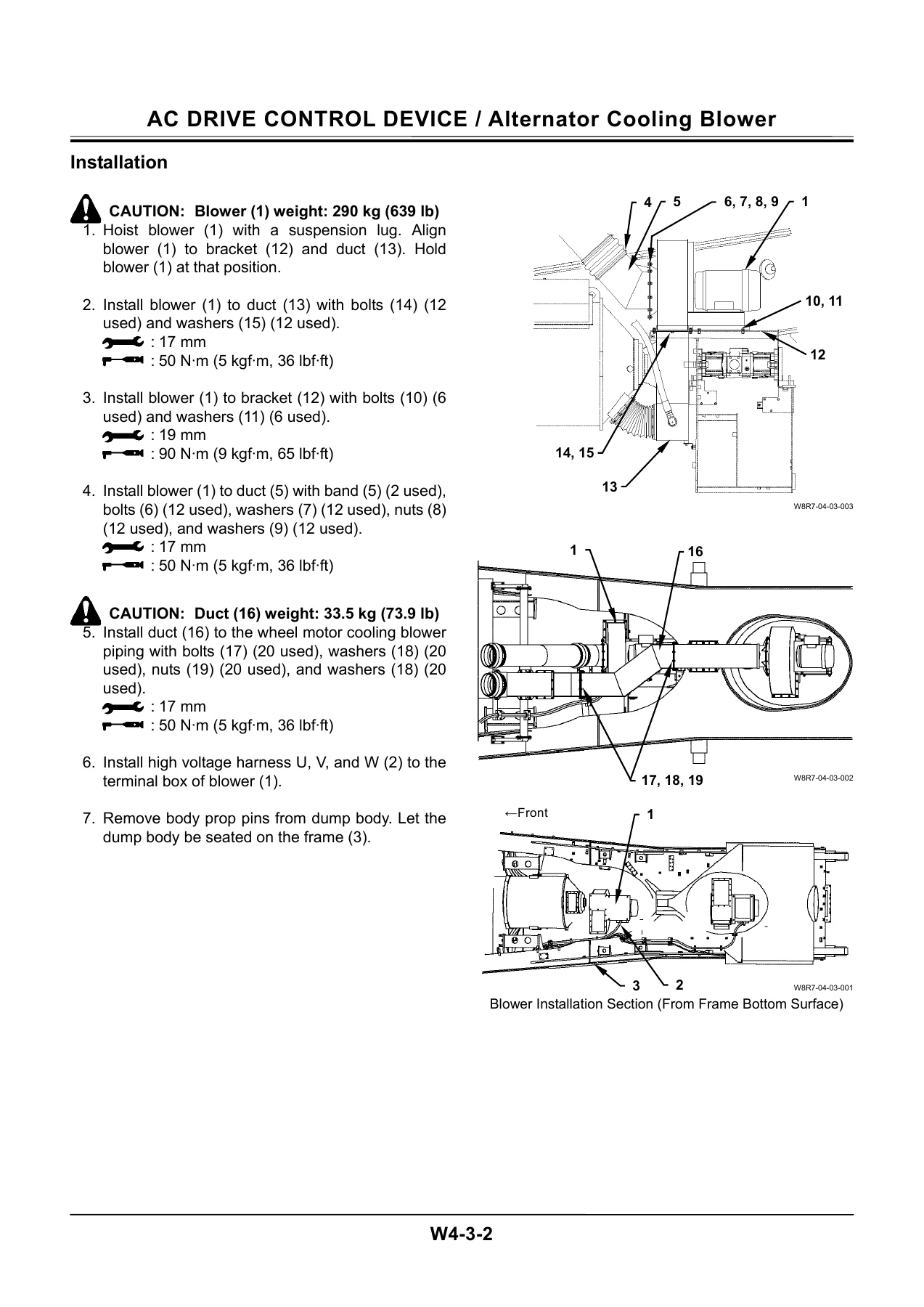
Group 3 Alternator Cooling Blowerp. 753
Removal and Installation of Alternator Cooling Blowerp. 753
Group 4 Wheel Motor Cooling Blowerp. 755
Removal and Installation of Wheel Motor Cooling Blowerp. 755
SERVICE MANUAL REVISION REQUEST FORMp. 759

Hoist and Driveline Procedures

The Hoist Device section documents removal, disassembly and assembly of the hoist control valve, the 4-unit proportional control solenoid valve, the hoist cylinder and the dump body itself, each with weight callouts and exploded parts breakdowns. The Body section works through the driveline, front axle, tire/rim/air-pressure procedures, front brake and brake valve/accumulator service, and the frame suspension cylinder, while the AC Drive Control Device section covers the control cabinet, grid box and the alternator and wheel-motor cooling blowers unique to this AC-drive rigid dump truck.

Whether you’re pulling the hoist control valve for a rebuild, retorquing cab or engine mounts to factory spec, or servicing the alternator cooling blower on this Hitachi EH4000AC II, this Workshop Manual gives you the exact procedures, torque values and part callouts Hitachi wrote for the job. Correct torque and assembly sequence directly affect the safety and service life of a machine this size, so working from the actual EH4000AC II Workshop Manual instead of guesswork protects both the machine and the technician. It downloads instantly as a PDF after checkout, works on any phone, tablet, laptop or shop PC, needs no shipping or waiting, and can be printed page-by-page for the shop floor whenever you need this Hitachi EH4000AC II Workshop Manual on hand.
Reviews

There are no reviews yet.

Be the first to review “Hitachi EH4000AC II Rigid Dump Truck Workshop Manual – Part No. W8R7-E-00”

What Our Customers Say

β˜…β˜…β˜…β˜…β˜… Live reviews from customers
Loading customer reviews...
0
    0
    Your Cart
    Your cart is emptyReturn to Shop
    πŸ›’
    Recently Purchased
    πŸ•’ verified order