
Hitachi EH5000AC-3 Rigid Dump Truck Technical Manual – Operational Principle
Original price was: $44.95.$27.95Current price is: $27.95.
The complete Operational Principle Technical Manual for the Hitachi EH5000AC-3 rigid dump truck (TOQHA-EN-02) – 663 pages covering machine specifications, control systems, travel system, hydraulics, electrical systems, AC drive component operation, engine, alternator, brake, steering, suspension and hoist devices.
Description
Hitachi EH5000AC-3 Rigid Dump Truck Technical Manual – Operational Principle
This is the complete Operational Principle volume of the factory Technical Manual for the Hitachi EH5000AC-3 rigid dump truck, published by Hitachi Construction Machinery Co., Ltd. under document number TOQHA-EN-02. Where a Workshop Manual tells you how to remove and install parts, this Hitachi EH5000AC-3 Technical Manual – Operational Principle explains how the machine actually works: how the AC drive system produces and controls power, how the hydraulic circuits route oil through hoist, steering and brake functions, how the controllers talk to each other over CAN, and how every major component on the truck operates in sequence. It is the reference a technician reaches for when a fault needs to be understood from the inside out before a repair is attempted.
File Details
- Manual type: Technical Manual – Operational Principle
- Brand: Hitachi Construction Machinery
- Model: EH5000AC-3
- Document number: TOQHA-EN-02
- Language: English
- Page count: 663 pages
- File format: PDF
Chapters Covered
The contents are organised into the sections below. Each section groups the information a technician needs for a different level of understanding, from overall machine data down to individual component operation.
- Section 1 – General
- Machine Specifications (dimensions, capacities, weights, travel speed, tire size)
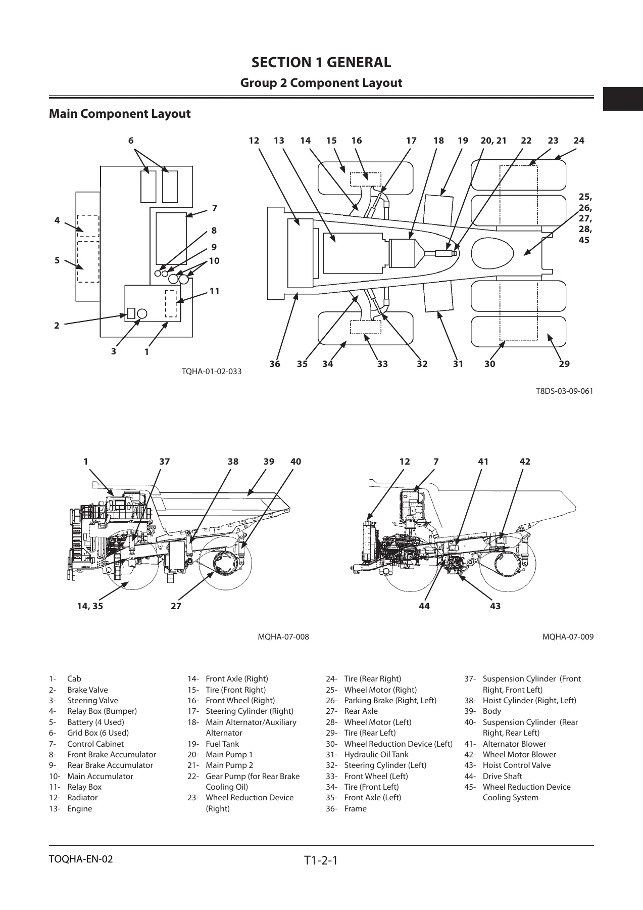
- Component Layout (main component layout, operator’s station, LCD screens, console panel, lights, fuse and relay boxes for both Cummins and MTU engines, hydraulic components, control cabinets, grid box)
- Component Specifications (Cummins and MTU engine data, engine accessories, alternator, control cabinet, pump device, travel device, brake, steering, suspension, hoist, fuses, relays, sensors, lights, filters)
- Section 2 – System
- Control System (CCU functions, brake control, hoist control, reduction gear cooling oil control, alarm/failure judgment, controllers and communication buses)
- Travel System (AC drive power supply circuits, DC 24 V power control, auxiliary alternator field regulator, main alternator field regulator, DC high-voltage control, engine control, travel control, acceleration and deceleration, cruise control, auto retard, grid blower control, cooling pump and wheel motor blower control, control cabinet temperature control)
- Hydraulic System (hoist circuit, main pump 2 circuit, service brake circuit, parking brake circuit, steering circuit, wheel reduction device cooling circuit, brake cooling circuit)
- Electrical System (electric power circuits for Cummins and MTU engines, starting circuits, charging circuits, engine stop, surge voltage prevention, emergency engine stop, indicator and light circuits, parking brake and load/dump brake circuits)
- Other System (load weighing system, machine body stability control / HDC)
- Section 3 – Component Operation
- Engine
- Alternator (main and auxiliary)
- Control Cabinet (DSC, control power unit, AFR unit, MFR unit, rectifier unit, inverter unit, auxiliary inverters, grid box)
- Pump Device (main pump, regulator, brake cooling gear pump)
- Travel Device (wheel motor, wheel reduction device, rear axle, front axle, front wheel, tires and rims)
- Brake Device (rear brake, front brake, parking brake, brake valve, load/dump brake valve, brake accumulator)
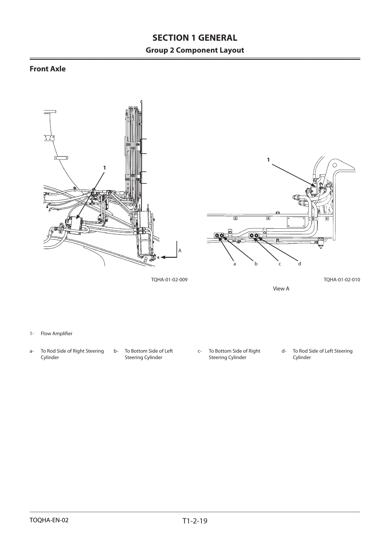
- Steering Device (steering column, steering valve, flow amplifier, steering cylinder, RCB valve, main accumulator)
- Suspension (front and rear suspension cylinder operation)
- Hoist Device (hoist control valve, 4-unit proportional control solenoid valve, hoist cylinder, hoist priority valve, manual body down valve, hoist lever)
Read as a whole, the EH5000AC-3 Operational Principle manual gives the reader a working mental model of the truck. Starting from the machine-level specifications and the physical location of every major component, it moves into the system level – the control, travel, hydraulic and electrical networks that make the machine move and work – and then drills down into component-level operation. That progression is what makes it useful not only when something has failed but also when you simply need to understand a circuit before you touch it.
What This Hitachi EH5000AC-3 Technical Manual Covers
The travel system chapters are among the most valuable in this document. The EH5000AC-3 is driven by a Hitachi AC-Drive system, and this manual explains how that system generates, rectifies, inverts and controls power from the main alternator to the wheel motors. The DC 24 V power control chapter, the auxiliary alternator field regulator (AFR) unit chapter, the main alternator field regulator (MFR) unit chapter and the high-voltage DC control chapter together describe the full signal and power chain, including the checks performed by the drive system controller (DSC) and the fault conditions it looks for.
Hydraulic coverage is equally deep. The hoist circuit is documented position by position – Raise, Hold, Float and Power Down – with descriptions of how main pump 1 and main pump 2 combine, how the hoist priority valve is shifted, and how the 4-unit proportional control solenoid valve drives each motion. The main pump 2 circuit explains accumulator charging, standby, and bleed-down on engine shutdown, while the service brake and parking brake circuits document brake valve operation, low-pressure sensor valve behaviour, and the RCB (relief check bleed) valve.
The control system section explains how the central control unit (CCU) receives inputs from hoist lever, pressure sensors, incline sensor and oil level switches, and how it exchanges information with the engine control module (ECM) and the DSC over CAN (SAE-J1939 and Ke-CAN). Alarm and failure judgment logic for fuel level, alternator voltage, communication errors, reduction gear cooling oil, hydraulic oil, air filter restriction and brake cooling oil is described here.
The electrical system section is split by engine variant. Dedicated chapters for the Cummins engine and for the MTU engine walk through the electric power circuit in key-switch OFF, ON and ACC states, followed by pre-lubrication and starting circuits, charging circuits, engine stop, surge voltage prevention, emergency engine stop, turn signal and hazard, brake light, headlight, marker light, rear light, entrance light, side deck light, work light and horn circuits. Both the Cummins QSK60 and the MTU 16V4000 are covered, together with the serial number ranges that distinguish later-build machines.
Component-Level Operation and Reference Data
Section 3 turns to individual components. Engine, alternator, control cabinet, pump device, travel device, brake device, steering device, suspension and hoist device each receive their own chapter. The control cabinet chapter is particularly detailed – drive system controller (DSC), control power (CS) unit, AFR unit, MFR unit, rectifier (REC) unit, inverter (INV) unit and the four auxiliary inverters (INV301 through INV304) each have their own operating circuit diagrams and failure-detection descriptions, ending with a full function table of electrical circuit components that lists every major device, its abbreviation and its role.
Throughout the document, the machine specifications tables give the reader the numbers needed to judge a repair: dump body capacity of 202 m³ (264 yd³), operating weight of 204,000 kg (450,000 lb), nominal payload of 296,000 kg (653,000 lb), target gross machine operating weight of 500,000 kg (1,100,000 lb), overall length of 15,490 mm, overall width of 9,600 mm, minimum turning diameter of 29.9 m, and forward travel speed of 56 km/h. Tire size is 53/80R63. These are printed alongside dimensioned drawings of the machine, so a reader can match a measured value against the specification directly.
Who This Technical Manual Is For
This is a technician-level document, not an operator’s guide. It assumes familiarity with heavy mining equipment, electrical schematics and hydraulic circuits. Independent repair shops, field service technicians and maintenance planners supporting the EH5000AC-3 will find it most useful when diagnosing electrical or hydraulic faults that require understanding how a subsystem is meant to behave before a fault can be located. Because the manual covers both the Cummins and MTU engine variants, and because serial number ranges are used to distinguish build differences (for example front and rear suspension cylinder specifications differ between earlier and later machines), owners and fleet managers can confirm the correct data for the specific truck in front of them.
Get Immediate Access to the EH5000AC-3 Operational Principle Manual
With this Hitachi EH5000AC-3 Technical Manual – Operational Principle on hand, you can trace a fault through the AC drive system, confirm how a hoist or steering circuit is supposed to sequence, check the electrical circuit for a lighting or starting problem, or read the function table to identify an unfamiliar control cabinet component – all without waiting for a service call. Correct procedures and correct specifications matter on a machine of this size, and this manual is the source for both.
Delivery is instant. The PDF is available immediately after checkout, with no shipping and no waiting. Read it on a laptop in the workshop, on a tablet next to the machine, or print the specific pages you need for the job in front of you.
IMAGES PREVIEW
Reviews
There are no reviews yet.