
Hitachi EX1200-5 Excavator Workshop Manual – PDF Service & Repair Guide
Original price was: $44.95.$27.95Current price is: $27.95.
Complete Hitachi EX1200-5 excavator Workshop Manual in PDF – disassembly, assembly, tightening torque, hydraulic components, undercarriage, front attachment and cylinder repair procedures for backhoe and loading shovel variants.
Description
Hitachi EX1200-5 Workshop Manual – PDF Service & Repair Guide
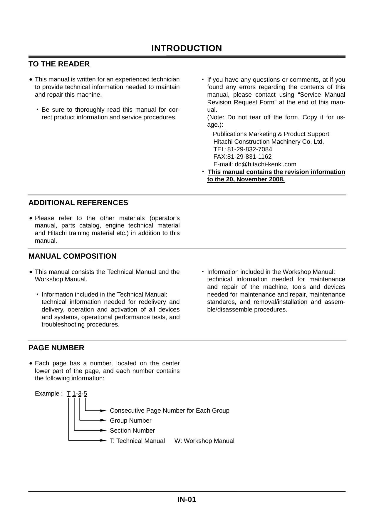
This is the full Hitachi EX1200-5 Workshop Manual, the technical document a shop technician works from when a machine has to come apart. It covers the complete excavator in both backhoe and loading shovel configurations, from the cab and counterweight down through the pump transmission, control valve, swing device, travel reducer, track frame and the front attachment cylinders. Every removal, disassembly, assembly and installation procedure in the manual is written step by step with wrench sizes, tightening torques and matching-mark notes attached to the individual fasteners.
Because the same document also carries the Technical Manual material, it does more than list repair steps. It gives the operational principles behind each system, the performance test values, and the troubleshooting flow for faults, so a technician can work from symptom to failed component rather than guessing.
File Details
- Manual type: Workshop Manual (with Technical Manual content)
- Brand: Hitachi
- Model: EX1200-5
- Publisher: Hitachi Construction Machinery Co., Ltd.
- Language: English
- File format: PDF
- Page count: 467 pages
- Revision information to: 20 November 2008
- Copyright: 1999 Hitachi Construction Machinery Co., Ltd., Tokyo, Japan
- Units: SI units, with MKS and English units in parentheses
Chapters Covered
- Section 1 – General Information
- Group 1: Precautions for Disassembling and Assembling (cleaning, inspection, tooling, matching marks, bleeding air from the hydraulic system, handling floating seals and nylon slings, maintenance standard terminology)
- Group 2: Tightening Torque (torque specification, torque chart, piping joints, seal tape application, low-pressure hose clamp torque, periodic replacement of parts)
- Section 2 – Upperstructure
- Group 1: Cab (cab removal and installation, cab bed, fender assemblies, cab glass dimensions)
- Group 2: Counterweight
- Group 3: Pump Device (pump transmission disassembly/assembly, main pump, regulator, oil cooler fan motor pump and its regulator, pilot pump, lubricating pump transmission)
- Group 4: Control Valve (main control valve and swing control valve removal, disassembly and assembly of the 5-spool and 4-spool sections, manifold, overload relief valves, main relief valve, make-up valves, holding valves)
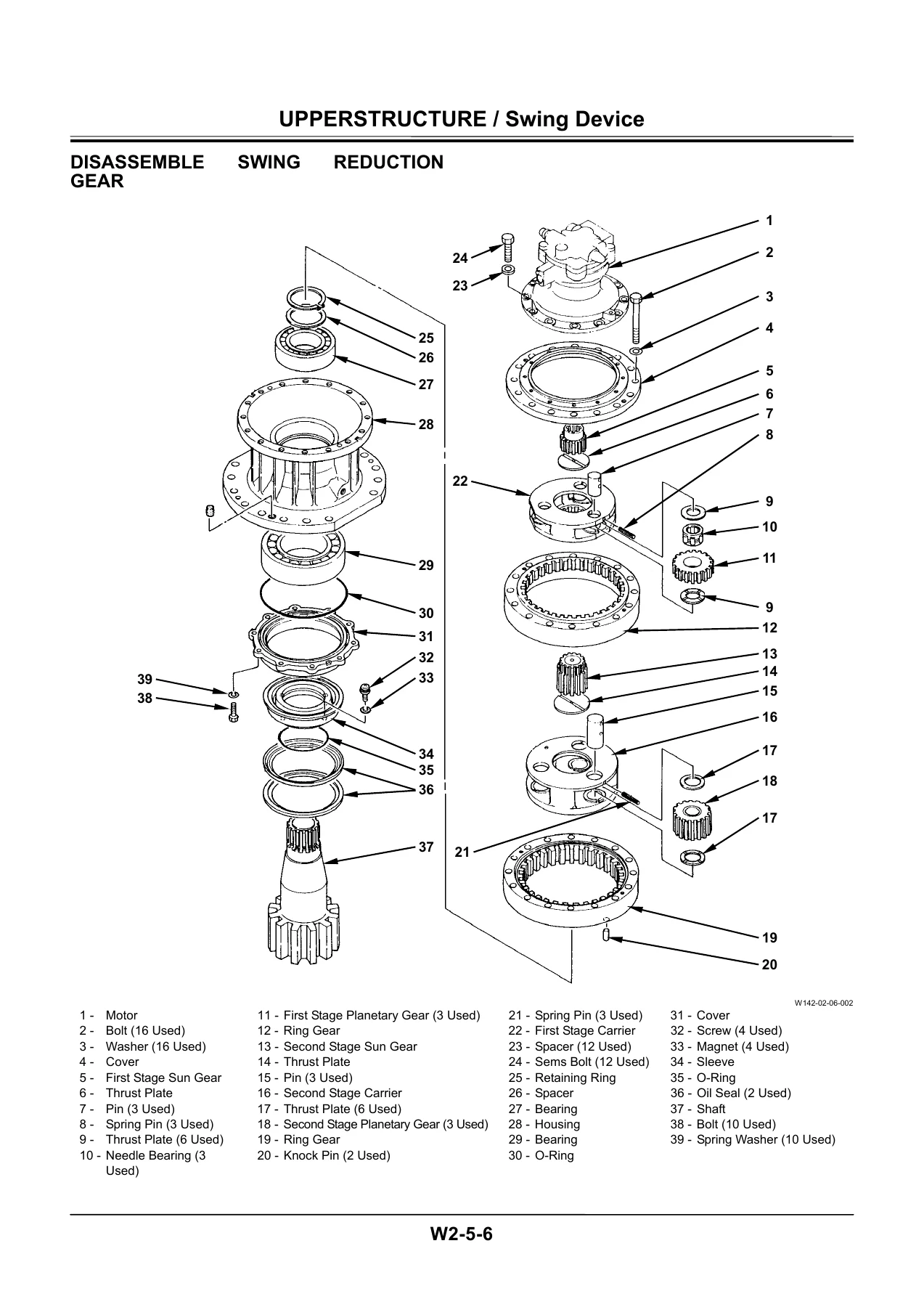
- Group 5: Swing Device (swing reduction gear, swing motor, swing parking brake releasing valve)
- Group 6: Pilot Valve (right, left, travel and bucket pilot valves)
- Group 7: Pilot Shut-Off Valve
- Group 8: Shockless Valve
- Group 9: Solenoid Valve (boost, oil cooler fan control, flow rate reducing, heavy lift, 2-speed travel, boom mode selector, power decreasing)
- Group 10: Signal Control Valve (pilot port and control valve side port identification)
- Group 11: Oil Cooler Fan Motor
- Section 3 – Undercarriage
- Group 1: Swing Bearing (removal, installation, ball and support replacement, matching marks and soft zone positioning)
- Group 2: Travel Device (travel reducer, travel motor, travel brake valve, sprocket, floating seal)
- Group 3: Center Joint
- Group 4: Track Adjuster (spring compression and release using the special tooling)
- Group 5: Front Idler
- Group 6: Upper and Lower Roller
- Group 7: Track (master pin removal and installation, track sag adjustment)
- Section 4 – Front Attachment
- Group 1: Front Attachment (bucket, arm and boom removal and installation for both backhoe and loading shovel, greasing points)
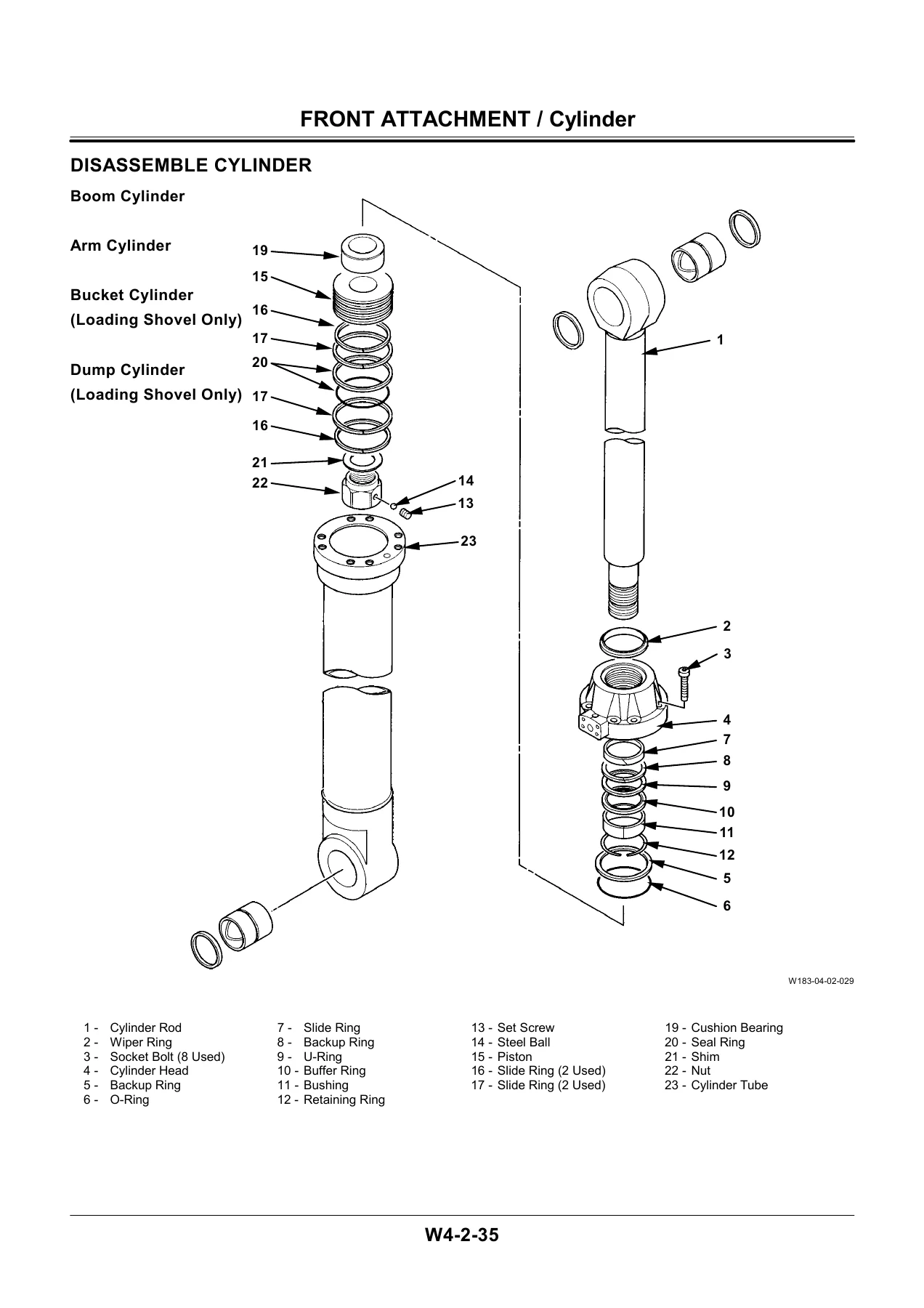
- Group 2: Cylinder (boom, arm, bucket, level and dump cylinder removal, disassembly, assembly, nut tightening and air bleeding)
- Group 3: Bushing and Point (bushing removal and installation, bushing install tool numbers, wear limits for pins and bushings, side cutter and point limits)
- Section 5 – Engine
- Technical Manual – System
- Control System, Hydraulic System, Electrical System
- Technical Manual – Component Operation
- Pump Device, Swing Device, Control Valve, Pilot Valve, Travel Device, Uppermost and Undercarriage components
- Technical Manual – Operational Performance Test
- Engine Test, Excavator Test, Hydraulic Component Test, Standard Values, Electrical System Inspection
- Technical Manual – Troubleshooting
- Introduction, Component Layout, Troubleshooting A, B and C
What this gives a technician is a single source covering the whole machine. Disassembly work is written so that parts come off without damage, matching marks and tag positions are called out, and every seal, O-ring, backup ring and floating seal gets its installation note. Reassembly is written to the same level, with the specific torque for each bolt group, the correct grease or thread-locking compound where one is required, and the sequence for tightening multiple bolts evenly.
Systems and Assemblies Documented
The hydraulic side of the Hitachi EX1200-5 is handled in depth. The pump device section covers the pump transmission, main pump, and the pump that drives the oil cooler fan motor, including their regulators. Regulator disassembly and assembly is broken down to individual pins, sleeves, spools, feedback levers, compensating rods and pilot pistons, with notes on which parts should not be separated and where marks should be applied so that the original flow setting is preserved.
The control valve material documents both the main control valve and the swing control valve, section by section. Spool assemblies, caps, springs, check valves, load check valves, holding valves, make-up valves, shuttle valves, flow-combining valves and the manifold are all covered, along with the overload relief valves and main relief valves that must be returned to their original positions and re-adjusted on a test bench.
On the undercarriage, the swing bearing procedure describes how the balls and supports are removed and reinstalled through the plug hole, and it stresses the matching marks and soft zone positioning that must be observed. Travel device coverage includes the three-stage travel reducer, the travel motor with its brake piston and friction and disc plate stack, and the travel brake valve with its overload relief valves and check valves.
The front attachment section is written for both machine configurations. Backhoe and loading shovel bucket and arm removal follow separate procedures because the linkage and cylinder arrangements differ, and the boom removal and installation procedure is documented for both. Cylinder work includes nut tightening with the correct nut turning tool per cylinder, the contour dimension checks on the cushion bearing, and the crimping of the set screw after the steel ball is installed.
Specification and Tolerance Data
Wear limits and allowable tolerances are given in table form where the assemblies need them. Main pump plunger-to-bore clearance, spring free length, plunger-to-shoe clearance and shoe thickness, and retainer plate height are listed with both standard and allowable limit values. The swing motor has its own set covering plunger, rotor bore, shoe thickness, friction plate thickness and holder height. Travel motor clearances, sprocket dimensions and bushing wear limits are included, as are track link pitch measurement, master pin and bushing dimensions, grouser shoe limits, front idler and roller limits, and pin and bushing dimensions for the whole front attachment across both backhoe and loading shovel.
Who This Manual Is For
This Hitachi EX1200-5 Workshop Manual suits a heavy equipment mechanic, a shop foreman supervising a rebuild, or an owner-operator who maintains their own machine and wants the actual factory procedures rather than a generic repair guide. It also suits technical trainers or fleet maintenance planners who need the torque tables and wear limits on hand.
Torque values are set out in a full chart as well as at the point of use, covering everything from engine cushion rubber mounting bolts and engine bracket bolts through to counterweight mounting bolts, swing bearing bolts, travel device bolts, sprocket bolts, shoe mounting bolts and side frame bolts. Piping joints get their own tables covering union nuts, hose fittings, screw-in connections for tapered and straight threads, and the correct seal tape application.
Why the Right Procedure Matters on an EX1200-5
An excavator of this size carries stored energy in several places. The track adjuster spring, the swing bearing ball set, the travel motor brake stack and the front attachment cylinders all require specific handling, and the manual calls out where a part can fly, where pressure must be released first, and where a plastic hammer or a press with a defined capacity should be used instead of force. Following those steps is the difference between a rebuild that lasts and one that leaks, seizes or fails early.
Flow settings on the pump regulators and pressure settings on the relief valves are equally unforgiving. The manual repeatedly notes that adjusting bolts, sleeves and set screws must go back to the exact position they came from, and that relief valves must be re-tested and adjusted on a bench. Without that guidance, a rebuilt valve can be assembled correctly and still leave the machine working at the wrong pressure.
IMAGES PREVIEW
Instant PDF Delivery
The Hitachi EX1200-5 Workshop Manual is delivered as an instant PDF download, with no shipping and no waiting for a physical book. It opens on a laptop, tablet or phone in the workshop, and any page, torque table or exploded view can be printed and taken to the machine. Search the document for a component name, a wrench size or a torque figure and go straight to the procedure.
Whether the job is a swing bearing replacement, a travel motor reseal, a control valve rebuild, a cylinder repack or simply finding the correct torque for a counterweight bolt, this PDF service and repair guide carries the procedure and the numbers to do it properly.

Reviews
There are no reviews yet.