
Hitachi ZAXIS 200 225 230 270 Class Excavator Technical Manual Troubleshooting TT178E-02
Original price was: $39.95.$24.95Current price is: $24.95.
Hitachi factory Technical Manual (Troubleshooting) TT178E-02 for ZAXIS 200, 225, 230 and 270 class excavators – operational performance test standards, Dr. ZX fault code diagnosis, hydraulic and electrical troubleshooting, monitor diagnosis and component layouts in a single PDF.
Description
Hitachi ZAXIS 200, 225, 230 and 270 class excavator troubleshooting is exactly what this volume delivers. Issued by Hitachi Construction Machinery Co. Ltd. under document number TT178E-02, this is the fault-finding half of the technical manual set – the book a technician reaches for once the machine is in the yard throwing a fault code, drifting, mistracking, or simply failing to make power. Where the Operational Principle volume explains how each circuit is meant to behave, this Hitachi ZAXIS Technical Manual Troubleshooting shows you how to measure it, what the numbers should be, and how to follow a symptom back to the failed component.
The ZAXIS 200 225 230 270 class excavator technical manual covers all four machine families in one document: the ZX200 class, the ZAXIS225US and 225USR class, the ZX230 class, and the ZX270 class. Each class gets its own performance standard tables, its own Dr. ZX monitor reference values, and its own sensor activating ranges, so you are never applying one machine’s specification to another.
File Details
- Manual type: Technical Manual (Troubleshooting)
- Document number: TT178E-02
- Publisher: Hitachi Construction Machinery Co. Ltd.
- Brand: Hitachi
- Machine classes: ZX200, ZX225, ZX230, ZX270
- Language: English
- Format: PDF – instant download
- Extent: 400+ pages
Chapters Covered
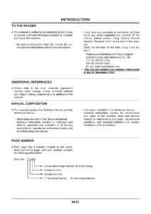
- To the Reader – how this Troubleshooting volume relates to the Technical Manual (Operational Principle) and the Workshop Manual, plus additional references
- Page numbering system, safety alert symbol and headline notations, units used (SI with MKSA and English conversions)
- Model classification table for all four machine classes
- Safety chapter – emergency preparation, protective clothing, noise protection, machine inspection, cab precautions, handholds and steps, operator’s seat adjustment, seat belt, safe movement and operation, jump starting, keeping riders off, signals, driving direction confirmation, slope driving, rollaway, back-over and swing accidents, tipping, power lines, object handling, flying debris, parking, fluid handling, waste disposal, welding and grinding
- Section 4 – Operational Performance Test
- Group 1 Introduction – purpose of performance testing, kinds of tests, performance standards, definition of performance standard, test area and precautions, precise measurement
- Group 2 Standard – operational performance standard tables for ZX200 class, ZAXIS225USR, ZAXIS225US, ZX230 class and ZX270 class, main pump P-Q diagram, injection pump governor adjustment, Dr. ZX monitor indicating values per class, sensor activating range
- Group 3 Engine Test – engine speed, engine compression pressure, valve clearance adjustment, nozzle check, injection timing, lubricant consumption
- Group 4 Excavator Test – travel speed, track revolution speed, mistrack check, travel parking function check, swing speed, swing function drift check, swing motor leakage, maximum swingable slant angle, swing bearing play, hydraulic cylinder cycle time, dig function drift check, control lever operating force, control lever stroke, combined boom raise/swing function check, boom raise and arm roll-in combined operation
- Group 5 Hydraulic Component Unit Test – primary and secondary pilot pressure, solenoid valve set pressure, main pump delivery pressure, main relief valve set pressure, swing and travel relief pressure, overload relief valve set pressure, main pump flow rate measurement, swing motor drainage, travel motor drainage
- Section 5 – Troubleshooting
- General – diagnosing procedure, built-in diagnosing system operation and display list, Dr. ZX operation and fault code list, Dr. ZX monitoring item list, Dr. ZX special function, Dr. ZX service mode, parameter change, monitor display change, adjustment data list, initial setting of boom electronic cushion
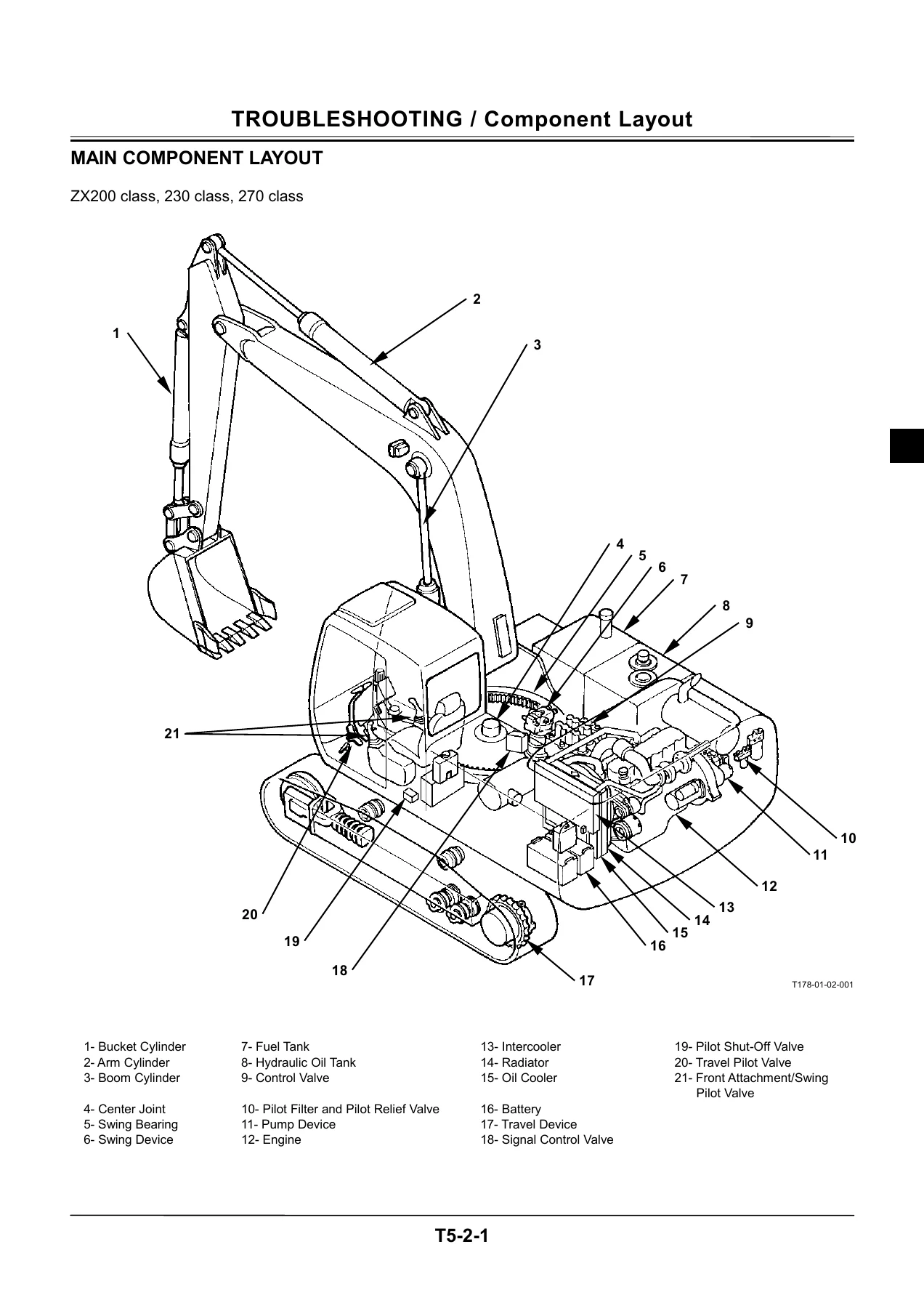
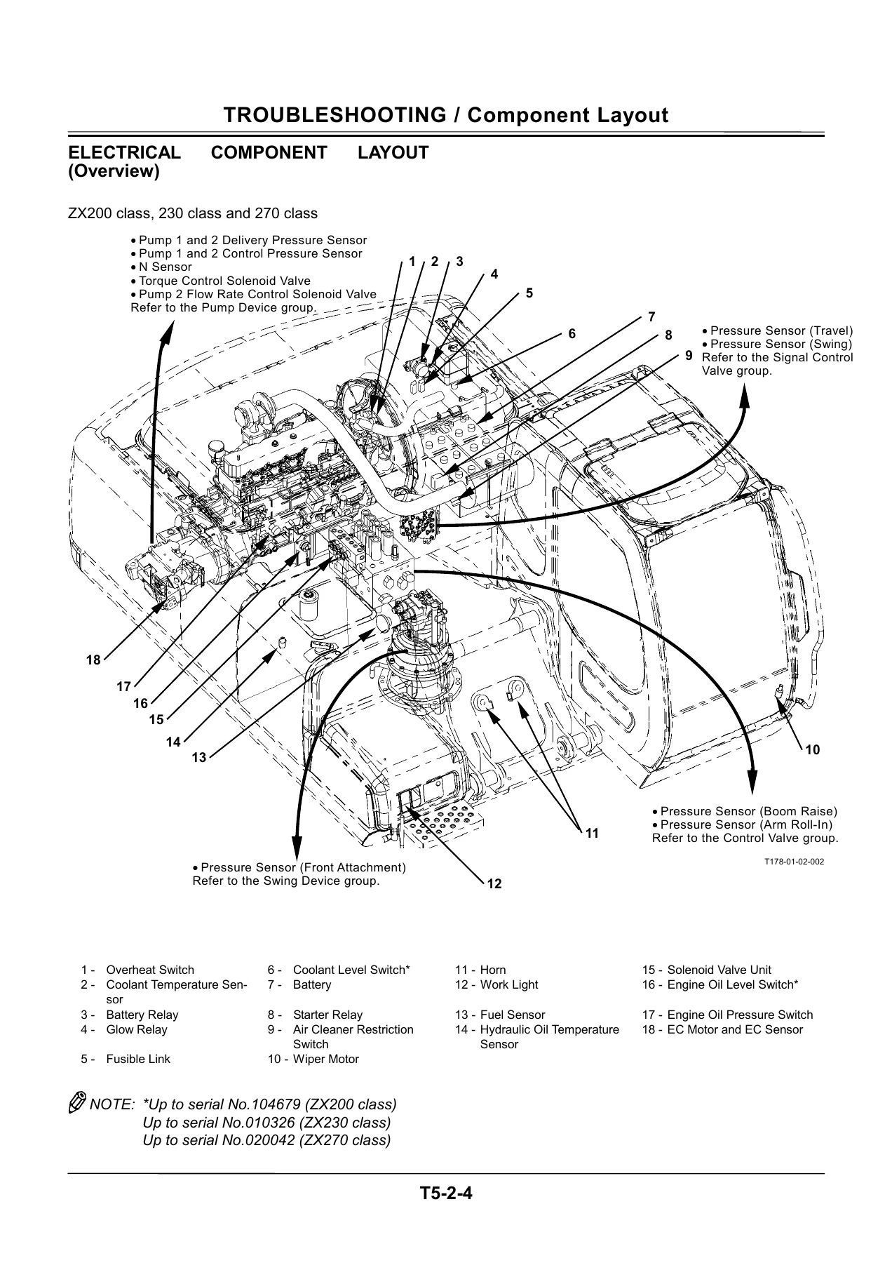
- Component Layout – main component locations, electrical component layout, electrical system relays and related equipment, monitors and switches, pump device, swing device, control valve, signal control valve, solenoid valve unit, travel device, positioning control valve (2-piece boom), components in control valve, signal control valve port location
- Troubleshooting A – base machine diagnosis using fault codes 01 to 19, with flow charts for EEPROM, RAM, A/D conversion, sensor voltage, EC sensor, engine control dial angle, boom angle sensor, pump delivery pressures, pump control pressures, swing/boom raise/arm roll-in/travel pilot pressures, and oil temperature
- Troubleshooting B – base machine diagnosis starting from abnormal operational status, including relationship tables between machine trouble symptoms and related parts, correlation tables between trouble symptoms and part failures, and full engine, all-actuator, front attachment, swing, travel and other system troubleshooting flow charts
- Troubleshooting C – monitor diagnosis for coolant temperature gauge, fuel gauge, indicator light check system, preheat indicator, engine oil level indicator, coolant level indicator, alternator indicator, engine oil pressure indicator, overheat indicator, air filter restriction indicator, buzzer, LCD and hour meter
- Group 6 Electrical System Inspection – precautions for inspection and maintenance, disconnecting connectors, fuse inspection and fuse table, fusible link inspection, battery voltage check, alternator malfunction troubleshooting, continuity check, voltage and current measurement, 5 volt circuit checks, check by false signal, test harness
- Group 7 ICX – outline, daily report data list, frequency distribution data list, cumulative operation hour list, alarm list, trouble list, ICX fault code list, satellite terminal fault code list, troubleshooting and setting of ICX and satellite terminal using Dr. ZX, satellite communication system
- Engine speed adjustment and engine learning procedure
- Emergency boom lowering procedure
Read as a whole, this Hitachi ZAXIS Technical Manual Troubleshooting gives a technician two things that are hard to find anywhere else in one place. The first is a complete set of measurable performance baselines – not generic guidance, but the actual figures Hitachi expects from each class at a defined hydraulic oil temperature of 50 ± 5 degrees C, with defined switch positions for every test. The second is a structured diagnostic path for when those baselines are not met: fault-code driven flow charts in Troubleshooting A, symptom-driven flow charts in Troubleshooting B, and instrument-driven flow charts in Troubleshooting C. Together they remove the guesswork from a machine that is behaving abnormally.
Operational Performance Standards for Every Class
The standard tables in Group 2 are the backbone of the volume. For the ZX200 class, for example, the tables list slow idle and fast idle engine speeds, fast idle with ECO deactivated, fast idle during relief operation, E mode and HP mode fast idle, auto-idle and auto-acceleration speeds and warming-up speed. Compression pressure is given as 3.04 MPa (31, 440) after engine warm-up, valve clearance as 0.4 mm with the engine cold, nozzle injection pressure as 18.1 MPa (185, 2630) and injection timing as 10 degrees before TDC. Travel speed, track revolution speed, mistrack allowance, swing speed, swing function drift, swing motor leakage, maximum swingable slant angle and swing bearing play all carry their own reference values and allowable limits. Hydraulic cylinder cycle times for boom raise, boom lower, arm roll-in, arm roll-out, bucket roll-in and bucket roll-out are listed to a tenth of a second, along with the arm and bucket configuration used for the test.
Relief pressures are documented in the same way: main relief valve setting for boom, arm and bucket, the power boost figure, swing relief pressure, travel relief pressure, and the separate overload relief valve settings for boom raise/lower, arm roll-in, bucket roll-in, arm roll-out and bucket roll-out. The same tables repeat for the ZAXIS225USR, ZAXIS225US, ZX230 class and ZX270 class with their own values, so the differences between classes are easy to compare side by side.
Engine and Hydraulic Testing Procedures
Group 3 walks through engine testing in practical detail – measuring engine speed with the built-in diagnosing system, Dr. ZX, an engine speed meter or a pulse counter, with the pulse-count-to-rpm conversion formula provided. The compression pressure procedure covers removing the glow plugs, fitting the adaptor and gauge, cranking and averaging three readings per cylinder. Valve clearance adjustment is documented with the TDC positioning method, the thickness gauge procedure and the lock nut tightening torque. Nozzle checking covers injection pressure, spray pattern and oil tight condition, with the adjustment sequence for the pressure screw. Injection timing uses the delivery valve method with the crank pulley TDC mark and the injection pump alignment mark viewed through the check hole. Lubricant consumption is measured over a 100-hour window with a defined filling and measuring routine.
On the hydraulic side, the unit test group explains how to plumb a hydraulic tester into the main pump delivery port, how to install a pulse counter on the N sensor, how to bleed the pump casing, and how to load the circuit to specific pressure points along the P-Q curve. A conversion formula is given so measured flow rates can be normalised to the specified pump speed for each class. The same chapter covers measuring swing motor drainage and travel motor drainage using a calibrated container and a per-minute conversion, with allowable limits stated.
Dr. ZX Fault Codes and Diagnostic Flow Charts
This ZAXIS excavator fault code manual section is where the volume earns its keep. The Dr. ZX fault code list covers abnormal EEPROM, abnormal RAM, abnormal A/D conversion, abnormal sensor voltage, abnormal EC sensor, abnormal engine control dial angle, abnormal boom angle sensor, abnormal pump 1 and pump 2 delivery pressure, abnormal pump 1 and pump 2 control pressure, abnormal swing, boom raise, arm roll-in and travel pilot pressure, and abnormal hydraulic oil temperature. Each code gets its own flow chart in Troubleshooting A, showing the exact connector terminal numbers to probe, the 5 ± 0.5 V supply check, the resistance checks, and how to tell a failed sensor from a broken harness or a faulty main controller.
Troubleshooting B is the other half of the equation. It opens with a relationship table between machine trouble symptoms and the parts that can cause them – EC motor, EC sensor, engine control dial, pump delivery and control pressure sensors, pilot pressure sensors, torque control solenoid valve, the individual solenoid valve units, boom and arm regenerative valves, anti-drift valves, flow combiner valve and the pump flow control valves. Each entry explains what happens in the control system when that part fails and what the operator will actually notice. From there, detailed flow charts cover engine symptoms E-1 through E-16, all-actuator symptoms A-1 through A-6, front attachment symptoms F-1 through F-10, swing symptoms S-1 and S-2, travel symptoms T-1 through T-5, and other system symptoms such as the wiper and air conditioner. The air conditioner section includes an eight-step self-diagnostic routine accessed from the control panel, with fault codes for the mix door, mode encoder, in-cab ambient temperature sensor, outdoor ambient temperature sensor, coolant temperature sensor and solar radiation sensor.
Monitor Diagnosis, Electrical Inspection and ICX
Troubleshooting C handles the monitor panel itself – coolant temperature gauge, fuel gauge, indicator light check, preheat indicator, engine oil level and coolant level indicators, alternator indicator, engine oil pressure indicator, overheat indicator, air filter restriction indicator, buzzer, LCD and hour meter. Each gauge or lamp gets a resistance or continuity chart with the sensor resistance values at stated temperatures, so a sensor can be judged rather than guessed at.
Group 6 Electrical System Inspection supplies the groundwork: how to disconnect the different connector styles found on the machine, how to test a fuse properly with a voltmeter rather than by eye, how to inspect the fusible link, how to check battery voltage before and after starting, how to troubleshoot the alternator circuit at the B and E terminals, how to run single-line and multi-line continuity and short-circuit checks, and how to use the 5 V circuit and false-signal checks. The test harness part numbers and their connection diagrams are reproduced for the EC motor circuit, the solenoid valve unit circuits, the EC sensor signal line and the wiper circuit.
Group 7 covers the ICX information controller – the data it records as daily report data, frequency distribution data, cumulative operation hours, alarms and troubles – along with the ICX and satellite terminal fault code lists and the satellite communication system layout for machines fitted with a satellite terminal.
Component Layout and Wiring Reference
Before the flow charts begin, the Component Layout group establishes where everything physically sits. Main component locations, electrical component layout overview, relay and fuse box arrangement, monitor and switch identification, pump device layout, swing device, control valve and signal control valve, solenoid valve unit, travel device and the positioning control valve used with the optional 2-piece boom are all illustrated and keyed. The control valve is then broken down further with numbered cross sections showing the load check valves, main relief valve, flow combiner valves, regenerative valves, anti-drift valves, flow rate control valves and overload relief valves in their actual positions. The signal control valve port location tables map every pilot port letter to the valve it connects to and the pressure it carries.
What This Manual Lets You Do
With this Hitachi ZAXIS 200 225 230 270 class technical manual on hand you can run a full operational performance test on any of the four classes and compare the results against the correct standard instead of a remembered figure. You can pull fault codes with Dr. ZX or the built-in diagnosing system and follow the matching flow chart to the failed sensor, broken harness or faulty controller. You can work a symptom that throws no code at all – slow travel, weak boom raise, mistracking, arm hesitation in a combined operation, swing drift, cylinder drift – through the correlation tables and reach the specific valve, solenoid or seal that is causing it. You can set relief pressures, adjust the pump regulator, correct engine speed, perform engine learning, and recheck your work afterwards. The job gets done once, to Hitachi’s own specification, instead of by substitution.
IMAGES PREVIEW
The manual is delivered as an instant PDF download – no shipping, no waiting, no physical book to keep clean in a workshop. Open it on a laptop, tablet or phone in the cab or in the yard, print the pages you need for the job, and keep the rest for the next machine. Whether you are servicing one ZX200 or running a mixed fleet of ZAXIS 200, 225, 230 and 270 class excavators, this Troubleshooting volume is the reference that turns a complaint into a measurement and a measurement into a repair.
Reviews
There are no reviews yet.