
Hitachi EX200-2 EX200LC-2 Technical and Workshop Manuals
Original price was: $39.95.$24.95Current price is: $24.95.
Combined technical and workshop manuals for the Hitachi EX200-2 and EX200LC-2 hydraulic excavators with Isuzu 6BD1T coverage, system theory, performance tests, troubleshooting, and overhaul procedures.
Description
Hitachi EX200-2 EX200LC-2 Technical and Workshop Manuals
This download brings together the Technical Manual and the Workshop Manual for the Hitachi EX200-2 hydraulic excavator and the long-undercarriage EX200LC-2. The first half explains how the machine is built and how its hydraulic, electrical, and control systems work. The second half walks through removal, disassembly, inspection, assembly, and installation of the major assemblies, plus a full engine-and-accessory workshop section for the Isuzu diesel family used in this model. Serial applicability shown in the weight tables begins at 147-60001- for both EX200-2 and EX200LC-2.
File Details
- Manual type: Technical Manual and Workshop Manual (combined)
- Brand / models: Hitachi EX200-2 and EX200LC-2
- Language: English
- Page count: 1151
- File format: PDF
- Section identifiers shown in the document: T-series technical pages and W-series workshop pages (examples include 107T-01-01 and 107W-01-01)
Machines Covered
Both machines share the same upperstructure layout and the same Isuzu 6BD1T engine rating of 99 kW (135 ps) at 2050 min-1. Standard front-end data is given for a backhoe with a 2.91 m (9 ft 7 in.) arm and a 0.8 m3 PCSA/SAE (0.7 m3 CECE/JIS) bucket. Operating weight is 18 500 kg (40 800 lb) on the EX200-2 and 19 000 kg (41 900 lb) on the EX200LC-2. Basic machine weight is 15 000 kg and 15 500 kg respectively. The LC undercarriage is longer and wider: sprocket-to-idler center 3 660 mm versus 3 370 mm, undercarriage length 4 460 mm versus 4 170 mm, and undercarriage width 2 990 mm versus 2 800 mm. Ground pressure with 600 mm grouser shoes is listed as 0.41 bar on EX200-2 and 0.39 bar on EX200LC-2. Swing speed is 11 min-1. Travel speeds are 2.5 / 3.5 / 5.5 km/h. Gradeability is 35° (tanθ = 0.70).
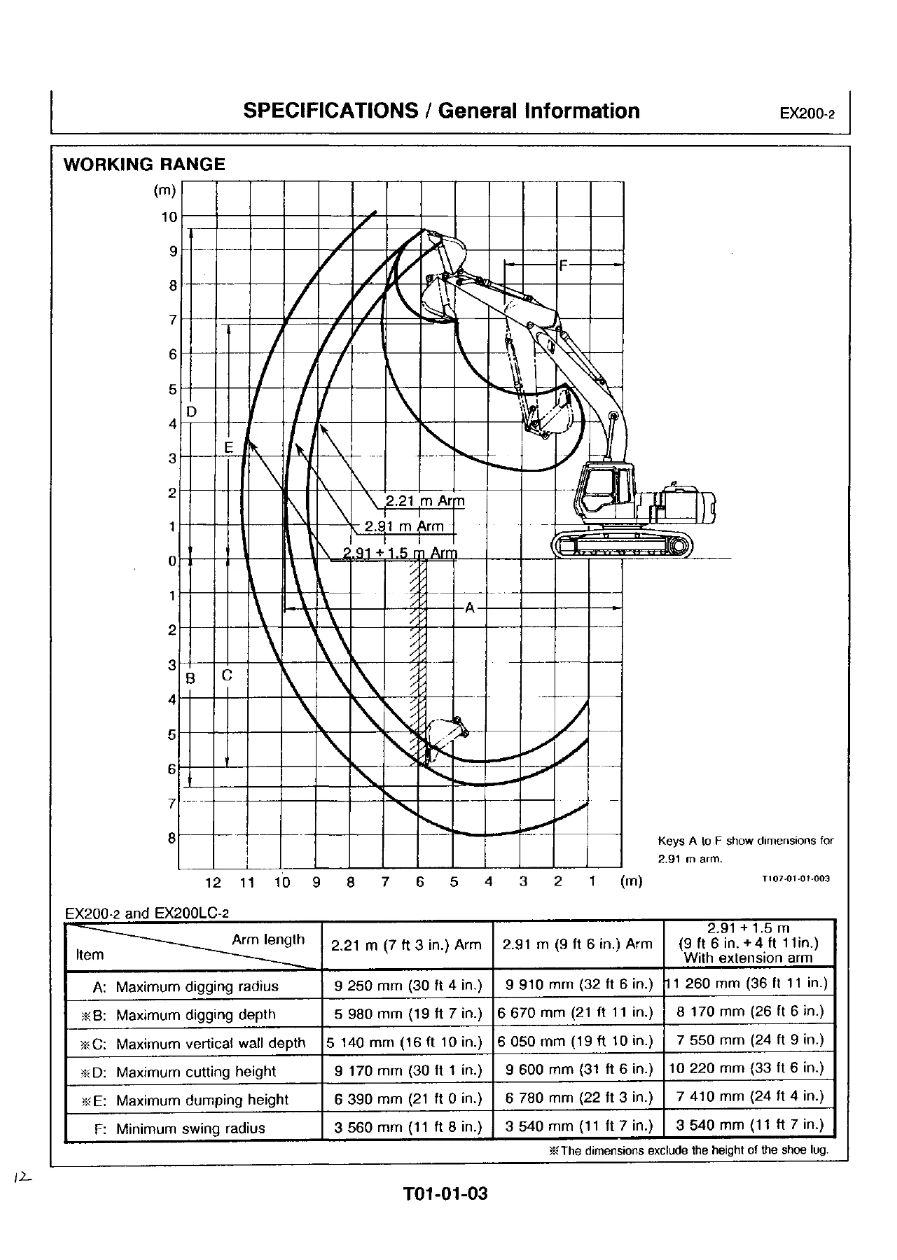
Working-range tables cover the 2.21 m arm, the 2.91 m arm, and the 2.91 m arm plus 1.5 m extension. On the 2.91 m arm the maximum digging radius is 9 910 mm, maximum digging depth 6 670 mm, and maximum cutting height 9 600 mm. Lifting-capacity charts are given separately for EX200-2 and EX200LC-2 with the 5.68 m boom, 2.91 m arm, 3900 kg counterweight, 0.8 m3 bucket, and 600 mm shoes. Service refill capacities include a 310 liter fuel tank, 21 liters of engine coolant, 25 liters of engine oil, 8.2 liters in the swing reduction gears, 5.5 liters in each travel reduction gear, 200 liters in the hydraulic system, and 130 liters in the hydraulic oil tank.
Chapters Covered
Technical Manual
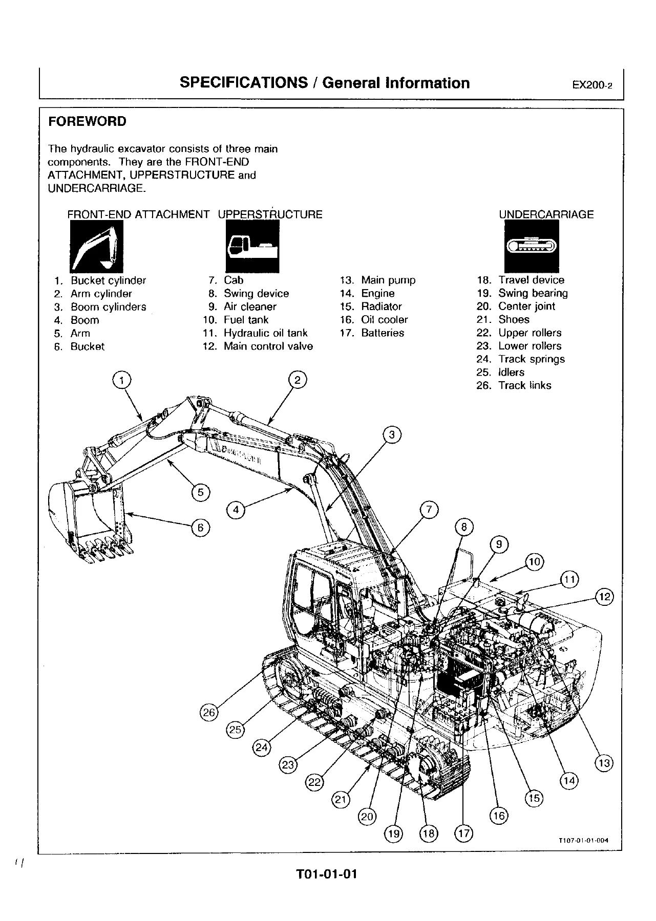
- Section 01 Specifications — general information, specifications, working range, lifting capacities, service refill capacities, transportation dimensions and weights, fuels and lubricants (fuel, grease, engine oil, gear oil, hydraulic oil, engine coolant), interchangeability with EX200, installation of attachments
- Section 02 Upperstructure — layout; hydraulic oil and fuel tanks; pump device (main pump HPV091, regulator, gear pump); swing motor, brake valve, parking brake, swing dampener valve, swing reduction; main and pilot piping; control valve (3-spool and 4-spool sides, system pressure regulator, surge relief, overload relief with anti-cavitation, variable pressure compensated valve, shuttle and holding valves); pilot valve; lock valve; shockless valve; accumulator; solenoid valve
- Section 03 Undercarriage — component location; swing bearing; center joint; travel reduction, travel motor, travel brake valve, parking brake; track adjuster
- Section 4 Electrical System — component location, monitor and switch panels, relays, electric wiring diagram, connectors; engine control system and EC motor; monitor functions; power, preheat, start, charging, accessory, auto-idle, and engine-stop circuits; fuse, fusible-link, A-sensor, and E.C. sensor service
- Section 05 Hydraulic System — main, suction, delivery, return, drain, and pilot circuits; load sensing and speed sensing pump control; valve and flow-dividing control; job mode selector; 3-speed propel; swing parking brake; warming-up and power-boost systems; neutral, swing, arm-in, combined, and relief circuits
- Section 06 Operational Performance Test — performance standards; engine speed and compression tests; travel speed, track revolution, mistrack, travel parking, swing speed and drift, swing motor leakage, swing bearing play, cylinder cycle time, dig-function drift, lever force and stroke, combined boom/arm and boom/swing checks; pilot primary/secondary pressure, PC pressure, swing-brake release, PI pressure, main-pump delivery, system-pressure regulator, overload relief, pump flow and PQ curve, swing and travel motor drainage; Dr. EX basic performance checks
- Section 07 Troubleshooting — diagnosing procedure and Dr. EX start-up, self-diagnosis and monitor functions; connector maps; Troubleshooting A fault codes for EC and PVC; Troubleshooting B engine, actuator, front-attachment, swing, travel, and other machine faults; Troubleshooting C monitor, gauge, and indicator faults; harness checks Test 1 through Test 14
Workshop Manual
- Section 01 Specifications — tightening torque charts and painting standard
- Section 02 Upperstructure — cab, counterweight, and main-frame R&I; pump device R&I, disassembly and assembly; four-section and three-section control valve R&I, disassembly and assembly; swing device and swing motor R&I, disassembly, assembly, and maintenance standard; front and travel pilot valves; shut-off valve; shockless valve; accumulator; solenoid, proportional solenoid, relief, and reducing valves; travel and swing/bucket shuttle valves; swing dampener valve
- Section 03 Undercarriage — swing bearing; travel device, travel motor, and brake valve; center joint; track adjuster; front idler; upper and lower rollers; track link — each with removal/installation, disassembly/assembly, and maintenance standards where listed
- Section 04 Front-End Attachments — boom/arm/bucket assembly removal and installation with pin-bushing limits; bucket, arm, and boom cylinder R&I; cylinder disassembly, assembly, inspection, and rod maintenance standard
- Section 05 Special Tool — special tool list and drawings
- Section 06 Engine and Accessory — general repair instructions, main data and specifications, design features, torque and identification; maintenance of lubricating, fuel, and cooling systems, valve clearance, injection timing, compression, turbocharger inspection; engine disassembly; inspection and repair of cylinder head through timing gear case; engine assembly; lubricating, cooling, and fuel systems; injection pump calibration data; turbocharger; air compressor; starter and alternator; engine troubleshooting; engine special tools
Taken as a whole, the Hitachi EX200-2 EX200LC-2 Technical and Workshop Manuals give a technician both the theory needed to understand load-sensing hydraulics, engine-control electronics, and Dr. EX diagnostics, and the shop steps needed to tear down and rebuild the pump, control valve, swing and travel motors, undercarriage, cylinders, and Isuzu engine. Safety pages at the front cover high-pressure fluid, battery acid, parking and supporting the machine, and lockout of the pilot shutoff lever.
Engine Workshop Scope
The engine section states that it applies to the 4BD1, 4BD1T, 6BB1, 6BD1, and 6BD1T industrial diesel family, with illustrations based on 6BD1 and 6BD1T. The excavator specification pages rate the machine on the turbocharged Isuzu 6BD1T. Main data for 6BD1T EX200-2 include a water-cooled four-cycle vertical in-line OHV direct-injection engine, six cylinders, 102.0 × 118.0 mm bore and stroke, 5 785 cm3 displacement, 17.5:1 compression ratio, fuel injection order 1-5-3-6-2-4, injection timing 16° BTDC, Bosch A-type in-line plunger pump with RSV mechanical governor, injection starting pressure 185 kg/cm2, compression pressure 31 kg/cm2 at 200 rpm, valve clearance 0.40 mm intake and exhaust (cold), IHI RHC6 turbocharger, 24-30 A alternator, and 24-4.5 kW starter. Use the 6BD1T columns and notes when working on the excavator engine; other family columns are shared industrial-engine data.
Fuels, Lubricants, and Service Intervals
Recommended fuel is high-quality diesel meeting ASTM D 975 No. 2D; kerosene is not to be used. Fuel service points cover draining water from the tank, checking the water sedimenter, replacing the fuel filter element, and cleaning the feed-pump strainer on the printed hour schedule. Grease points include front joint pins (boom foot, boom-cylinder bottom, bucket, and bucket link), remaining front pins, swing bearing, and swing gear, with a note for more frequent greasing during in-water work. Named EP2 greases from several suppliers are listed for -20 to 40 °C. Engine-oil, gear-oil, hydraulic-oil, and coolant charts in the same specification group set the approved products and change intervals used with the refill-capacity table.
Diagnostics and Performance Testing
Section 06 of the technical manual is the performance-test book for this machine. It lists standard values, then the field procedure for engine speed and compression, travel and swing behavior, cylinder cycle times, lever effort, and combined-function checks. Hydraulic component tests cover pilot pressures, proportional-solenoid PC pressure, swing-parking-brake release, reducing-valve PI pressure, main-pump delivery, system-pressure regulator relief, overload relief, pump flow against the PQ curve, and motor case drain. Adjustment steps sit next to many of those tests so a measured value can be corrected on the machine. Group 05 adds Dr. EX checks of P switches, relief versus neutral, the A-sensor (pump displacement angle), and single-operation behavior.
Section 07 then turns those measurements into a diagnostic path. Troubleshooting A lists EC-related and PVC-related fault codes and the flow charts for codes such as 01 through 06, 09, 10, 13, 17 through 22, and 25 through 32. Troubleshooting B maps electronic-component failures onto engine, actuator, front-attachment, swing, and travel symptoms and gives Dr. EX monitor items with reference values. Troubleshooting C isolates monitor-panel, gauge, and indicator faults. Group 06 harness checks run fourteen tests from the 24-volt battery circuit through sensor, pressure-switch, solenoid, EC-motor, engine-stop-motor, emergency-relay, and general relay circuits. An electric wiring diagram and connector location charts sit in the electrical section so those tests can be pinned out on the machine.
Workshop Overhaul Work
Workshop Section 02 is the upperstructure shop book: cab (about 230 kg), 3900 kg counterweight, main frame, HPV091 main-pump stack with pilot gear pump, three- and four-section control valves including load-check valves and the system pressure regulator, swing reduction and swing motor with maintenance limits, and the pilot, shut-off, shockless, accumulator, solenoid, shuttle, and swing-dampener valves. Section 03 covers the swing bearing, travel reduction and travel motor, center joint seals and wear limits, track adjuster spring and cylinder, front idler oil fill, upper and lower rollers, and track-link and master-pin limits. Section 04 gives front-attachment R&I, pin-and-bushing limits for the backhoe front, and complete cylinder overhaul for boom, arm, and bucket. Special-tool numbers (ST-series) are catalogued with drawings so the press, installer, and gauge setups called out in the procedures can be identified before work starts.
What This Manual Lets You Do
With the Hitachi EX200-2 EX200LC-2 Technical and Workshop Manuals on the bench you can identify the correct EX200-2 or EX200LC-2 configuration, verify working range and lift charts, service fuels and lubricants to the printed capacities, trace hydraulic and electrical circuits, run the operational performance tests, interpret Dr. EX and fault-code data, and carry out overhaul of the pump, valves, swing and travel drives, undercarriage, front attachment, cylinders, and Isuzu 6BD1T engine using the listed torques, maintenance standards, and special tools. Following the printed procedures and specifications keeps relief settings, pump flow, clearances, and assembly torque inside the values the machine was designed around, which is what separates a lasting repair from a guess. Delivery is an instant PDF after payment — no shipping wait — that you can open on any device and print the pages needed in the shop.
Reviews
There are no reviews yet.