
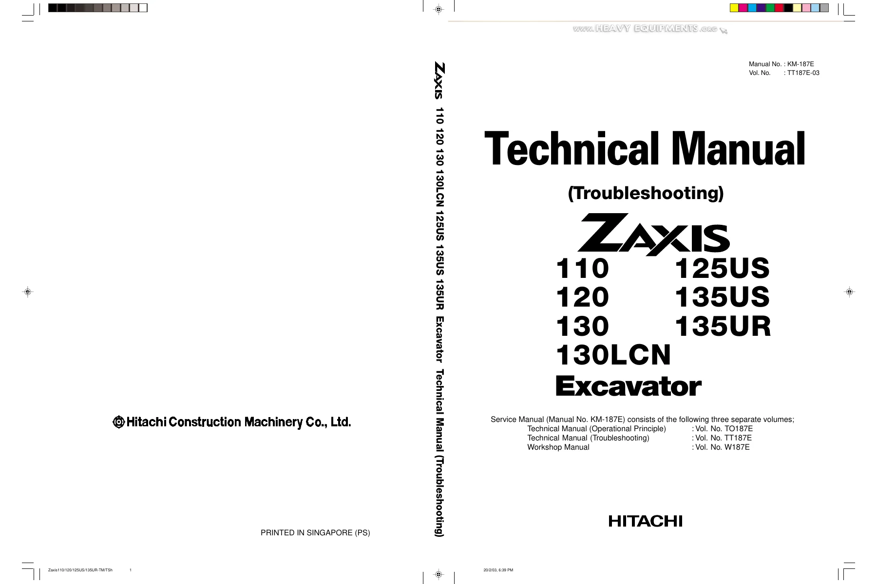
Hitachi ZAXIS 110 120 130 130LCN 125US 135US 135UR Excavator Technical Manual Troubleshooting PDF
Original price was: $39.95.$24.95Current price is: $24.95.
The complete Hitachi ZAXIS 110, 120, 130, 130LCN, 125US, 135US and 135UR Excavator Technical Manual (Troubleshooting) – Vol. TT187E. Over 440 pages of operational performance tests, fault code diagnostics, troubleshooting flow charts, electrical system inspection and component adjustment procedures.
Description
Hitachi ZAXIS Excavator Troubleshooting Technical Manual – Vol. TT187E
This is the Technical Manual (Troubleshooting) for the Hitachi ZAXIS 110, ZAXIS 120, ZAXIS 130, ZAXIS 130LCN, ZAXIS 125US, ZAXIS 135US and ZAXIS 135UR hydraulic excavators. Published under Manual No. KM-187E as Volume TT187E, this manual is one of three separate volumes that together form the complete service manual set. While the Operational Principle volume explains how systems work and the Workshop Manual covers removal and installation, this Troubleshooting volume is the dedicated diagnostic and performance testing reference – the book a technician reaches for when a ZAXIS excavator is not performing to specification or is displaying a fault code.
File Details
- Manual Type: Technical Manual (Troubleshooting) – Vol. TT187E
- Publication/Manual No.: KM-187E
- Brand: Hitachi Construction Machinery
- Models Covered: ZAXIS 110, ZAXIS 120, ZAXIS 130, ZAXIS 130LCN, ZAXIS 125US, ZAXIS 135US, ZAXIS 135UR
- Language: English
- File Format: PDF
- Page Count: 447 pages
- Units: SI units with MKSA and English conversions in parentheses
Chapters and Groups Covered
The manual is divided into two major sections – Operational Performance Test and Troubleshooting – each subdivided into focused groups. Here is the complete contents structure:
- Section 4 – Operational Performance Test
- Group 1: Introduction – purpose, kinds of tests, performance standards, test area, precautions, precise measurement
- Group 2: Standard – operational performance standard tables for ZAXIS110, ZAXIS120/130/130LCN, ZAXIS125US, ZAXIS135US and ZAXIS135UR; main pump P-Q diagrams; injection pump governor adjustment; Dr. ZX monitor indicating values for each model; sensor operational range table
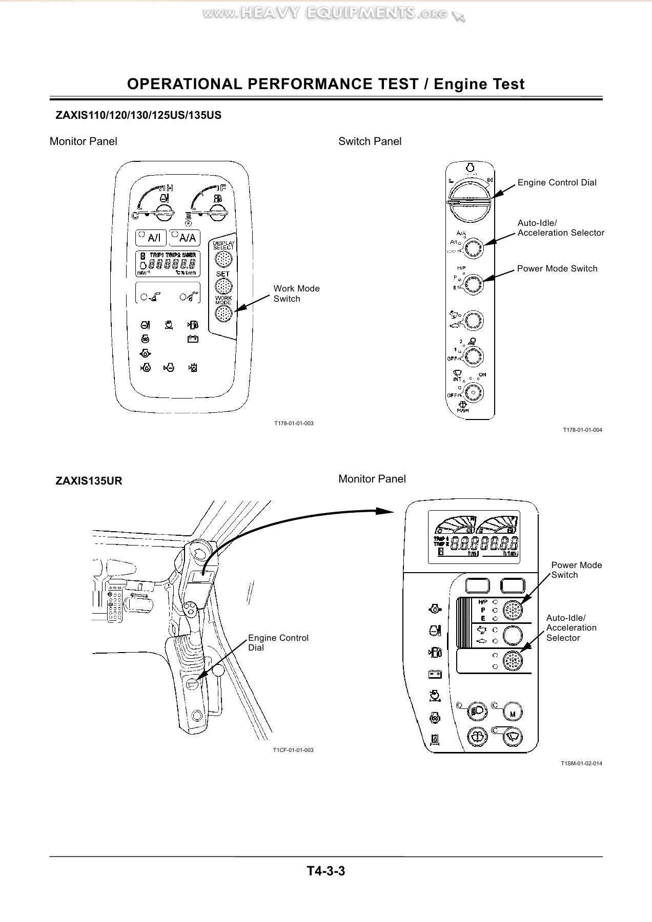
- Group 3: Engine Test – engine speed, engine compression pressure, valve clearance adjustment, nozzle check, injection timing, lubricant consumption
- Group 4: Excavator Test – travel speed, track revolution speed, mistrack check, travel parking function, swing speed, swing function drift, swing motor leakage, maximum swingable slant angle, swing bearing play, hydraulic cylinder cycle time, dig function drift, control lever operating force, control lever stroke, bucket/cab collision prevention system (ZAXIS135UR), combined boom raise/swing function, boom raise and arm roll-in combined operation
- Group 5: Component Test – primary pilot pressure, secondary pilot pressure, solenoid valve set pressure, main pump delivery pressure, main relief valve set pressure, relief pressure (swing/travel), overload relief valve set pressure, main pump flow rate measurement, swing motor drainage, travel motor drainage
- Group 6: Adjustment – assembly and adjustment of link for arm angle sensor (ZAXIS135UR), adjusting front acceleration/deceleration speed (ZAXIS135UR), initial setting of angle sensor (ZAXIS135UR), initializing depth limit control system (ZAXIS135UR), engine speed adjustment and engine learning, governor lever/fuel cut lever position
- Section 5 – Troubleshooting
- Group 1: General – diagnosing procedure, built-in diagnosing system operation, Dr. ZX operation, Dr. ZX fault code list (MC), fault code list (Auto-MARCCINO Controller), Dr. ZX monitoring item lists, Dr. ZX special function, engine learning, changing parameters, adjustment data lists
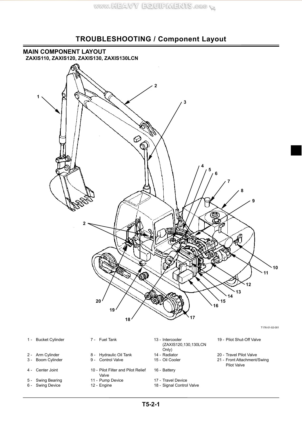
- Group 2: Component Layout – main component layout, electrical component layout, electrical system relays and related equipment, monitors and switches, pump device, swing device, signal control valve, control valve, solenoid valve unit, 8-unit solenoid valve unit (ZAXIS135UR), travel device, blade control valve, positioning control valve, components in control valve, signal control valve port location
- Group 3: Troubleshooting A – fault code list, fault code 01 (abnormal EEPROM), fault code 02 (abnormal RAM), fault code 03 (abnormal A/D conversion), fault code 04 (abnormal sensor voltage), fault code 06 (abnormal EC sensor), fault code 07 (abnormal engine control dial angle), fault code 10/11 (abnormal pump delivery pressure), fault code 12/13 (abnormal pump control pressure), fault code 14/15/16/18 (abnormal pilot pressure), fault code 19 (abnormal oil temperature)
- Group 4: Troubleshooting B – relationship between machine trouble symptoms and related parts, engine system troubleshooting (E-1 to E-16), all actuator system troubleshooting (A-1 to A-5), front attachment system troubleshooting (F-1 to F-11), swing system troubleshooting (S-1), travel system troubleshooting (T-1 to T-4), blade system troubleshooting (B-1 to B-2), other system troubleshooting (O-1 to O-3), exchange inspection method, emergency boom lowering procedure
- Group 5: Troubleshooting C – malfunction of coolant temperature gauge, fuel gauge, indicator light check system, preheat indicator, engine oil level indicator, coolant level indicator, alternator indicator, engine oil pressure indicator, overheat indicator, air filter restriction indicator, buzzer, LCD, hour meter, hydraulic oil filter indicator
- Group 6: Troubleshooting D (ZAXIS135UR Only) – fault code list (Auto-MARCCINO Controller), fault codes 05, 06, 07, 08, 11-13, 17, 14-16, 19-22, 37-44, 43/45/47/48, 50-53, 60-63, 80-83, 90, 91, 92
- Group 7: Electrical System Inspection – precautions for inspection and maintenance, instructions for disconnecting connectors, fuse inspection, fusible link inspection, battery voltage check, alternator malfunction troubleshooting, continuity check, voltage and current measurement, check by false signal, test harness
- Group 8: ICX – outline, daily report data list, frequency distribution data list, cumulative operation hour list, alarm list, trouble list, ICX fault code list, satellite terminal fault code list, fault codes 1 to 4 and 6, fault codes 7 to 10, some parts of data not recorded
This manual is built around the operational performance test and troubleshooting procedures that keep a ZAXIS excavator working within factory specification. The performance test section gives you the exact test conditions – hydraulic oil temperature of 50±5°C (122±9°F), specified switch positions, engine control dial settings – and the standard values you compare your measurements against. The troubleshooting section then takes over when a machine fails those tests or displays a fault code, walking through the diagnostic logic step by step until the faulty component is identified.
Operational Performance Testing
The performance test groups in this manual are not generic guidelines – they are the standard values for each specific ZAXIS model. The standard tables list engine speeds (slow idle, fast idle, HP mode, E mode, auto-idle, auto-acceleration, warming up), engine compression pressure, valve clearance, nozzle injection pressure, injection timing, lubricant consumption, travel speed, track revolution speed, mistrack allowance, swing speed, swing function drift, swing motor leakage, swing bearing play, maximum swingable slant angle, hydraulic cylinder cycle times, dig function drift, control lever operating force and stroke, primary and secondary pilot pressures, solenoid valve set pressure, main pump delivery pressure, main relief valve set pressure, swing and travel relief pressures, overload relief valve set pressure, main pump flow rate, and swing and travel motor drainage. Each standard value is given with its acceptable tolerance and the reference page for the corresponding test procedure. The main pump P-Q diagrams show the flow rate versus delivery pressure curve for each model group, with specific test points marked along the curve. The Dr. ZX monitor indicating value tables list the reference values for every monitor item – pump pressures, engine speeds, EC angle, dial angle, pilot pressures, proportional valve outputs, travel motor control pressure and EC motor position – for each ZAXIS model covered.
Troubleshooting and Diagnostics
Troubleshooting A is organized around fault codes. When you diagnose the main controller (MC) with Dr. ZX or the built-in diagnosing system and a fault code appears, you go to the corresponding fault code page. Each fault code page shows the fault code number, the problem description, the possible causes (faulty MC, faulty harness, faulty sensor), and a flow chart that steps through the diagnostic checks – voltage measurements at connector terminals, resistance checks, switching sensors to see if the fault code follows, checking harness continuity between the MC and the sensor. The fault codes covered include abnormal EEPROM, RAM, A/D conversion, sensor voltage, EC sensor, engine control dial angle, pump delivery pressures, pump control pressures, swing/boom/arm/travel pilot pressures, and oil temperature.
Troubleshooting B is the diagnostic path when no fault code is displayed but the machine is not operating correctly. It starts with a table that maps machine trouble symptoms to related parts – engine symptoms (E-1 through E-16), all actuator symptoms (A-1 through A-5), front attachment symptoms (F-1 through F-11), swing symptoms (S-1), travel symptoms (T-1 through T-4), blade symptoms (B-1 and B-2), and other system symptoms (O-1 through O-3). Each symptom has its own troubleshooting flow chart. The engine system charts cover starter not rotating, engine not starting even though starter rotates, engine stalling when control dial is fully rotated, engine speed not changing with control dial operation, engine speed not increasing after start, faulty HP mode, engine not stopping with key switch OFF, faulty auto-idle system, faulty E mode, faulty auto-acceleration system, engine hunting, engine not increasing speed in attachment mode, engine not decreasing speed in attachment mode, engine stalling after start, engine stalling under adverse conditions, and engine difficult to start at low temperature. The actuator charts cover slow speeds across all actuators, left or right travel inoperable in single operation, actuators not stopping when lever returns to neutral, and actuator speed faster than normal. The front attachment charts cover weak front attachment power, inoperable or slow cylinders, slow arm speed in combined operations, slow bucket roll-in, arm not moving smoothly at start of combined operation, boom not moving smoothly, boom or arm moving slightly downward before raising, front attachment drift, slow or immovable offset operation, offset cylinder drift, and abnormal front control (ZAXIS135UR).
Electrical System Inspection
Group 7 is a complete electrical diagnostic reference. It covers precautions for inspection and maintenance – disconnecting the power source, wire harness color coding, connecting and disconnecting terminal connectors, and circuit tester usage. The instructions for disconnecting connectors describe the push-to-unlock, pull-up-to-unlock, and pull-to-separate types, listing which connectors on the machine use each type. Fuse inspection explains how to check fuse continuity with a tester rather than visual inspection, and the fuse capacity table lists every fuse number, its amperage, and what circuit it protects. The fusible link inspection covers removal and replacement. Battery voltage check gives the normal voltage readings both with the engine stopped (24V) and running (26-28V). Alternator malfunction troubleshooting walks through checking the circuit and measuring voltage at the alternator terminals. Continuity checks are explained for single-line continuity, single-line short-circuit, multi-line continuity, and multi-line short-circuit testing. The voltage and current measurement section gives a table of every location to be measured – power source circuit, preheat circuit, starting circuit, charging circuit, surge voltage prevention circuit, and accessory circuit – with the engine and key switch conditions and the specification for each measurement. The 5V circuit check and false signal check are also covered, along with the test harnesses available for different circuits.
Additional Technical Content
The manual also includes the emergency boom lowering procedure, which explains how to lower the boom and bucket to the ground if the engine stalls and cannot be restarted. This procedure involves removing rubber caps from the boom I section of the 4-spool control valve, loosening lock nuts, and turning socket-head screws to control the boom lowering speed – with explicit warnings about not allowing anyone under the front attachment during the procedure. The exchange inspection method is also described, which is a troubleshooting technique where you switch a suspected faulty sensor or solenoid valve with an identical one from another circuit and see if the fault code follows the sensor or stays with the harness. The manual identifies which fault codes are applicable to this method – pump delivery pressure sensors, pump control pressure sensors, and pilot pressure sensors – and which are not (EC sensor, engine control dial, oil temperature sensor). The adjustment data lists in Group 1 give the adjustable range, minimum adjustment value, standard adjustment, and model for parameters like Li speed, WU speed, AI speed, E speed, P speed, breaker speed, crusher speed, vibro-hammer speed, pump swash angles, pump PQ base torque, ATT proportional solenoid valve, boom lower dampener proportional solenoid valve, ATT speed increase down wait time, ML crane codes, ML crane speed, ML crane bucket weight, and minimum boom cylinder bottom pressure over balance.
Who This Manual Is For
This troubleshooting manual is written for the experienced technician who maintains and repairs Hitachi ZAXIS excavators. It assumes you already understand how the machine systems work – the Operational Principle volume covers that – and gives you the diagnostic procedures, performance standards, and adjustment specifications needed to bring a machine back to factory specification. If you are diagnosing a fault code on a ZAXIS 110, 120, 130, 130LCN, 125US, 135US or 135UR, running operational performance tests to evaluate engine, travel, swing or hydraulic cylinder performance, measuring pilot or main relief pressures, checking swing or travel motor drainage, or troubleshooting an electrical circuit that is not setting a fault code, this manual provides the procedure and the standard value you compare against. The ZAXIS135UR-specific content includes the Auto-MARCCINO control system diagnostics, angle sensor initialization, depth limit control system initialization, and the additional fault codes and troubleshooting procedures that apply only to that model.
Get the Complete Hitachi ZAXIS Troubleshooting Manual
IMAGES PREVIEW
This Hitachi ZAXIS 110, 120, 130, 130LCN, 125US, 135US and 135UR Excavator Technical Manual (Troubleshooting) gives you the diagnostic procedures, operational performance test standards, fault code flow charts, electrical system inspection methods, and adjustment specifications needed to diagnose and repair these machines correctly. When a ZAXIS excavator is not performing to specification or is displaying a fault code, the correct procedure and the correct standard value are what separate a quick, accurate repair from guesswork that costs time and parts. The manual covers engine performance testing, hydraulic pump and valve testing, swing and travel system diagnostics, front attachment troubleshooting, electrical circuit inspection, and the Auto-MARCCINO control system diagnostics for the ZAXIS135UR. All 447 pages are delivered as an instant PDF download after payment – no shipping, no waiting for a physical book. You can view it on any device, print the pages you need for the shop, and keep the complete manual on hand for every ZAXIS excavator you service.
Reviews
There are no reviews yet.