
Hitachi Zaxis 110 110M 120 130 130LCN 125US 135US 135UR Excavator Technical Troubleshooting Manual TT187E PDF
Original price was: $60.95.$37.95Current price is: $37.95.
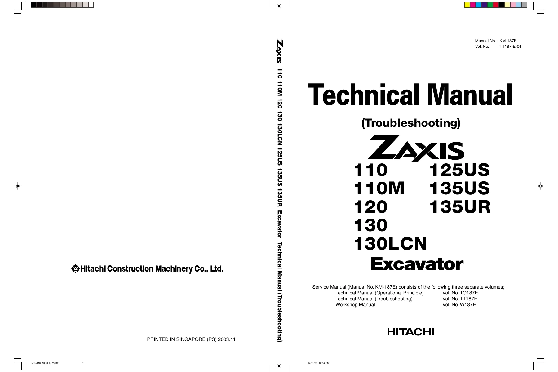
479-page Hitachi Zaxis excavator Technical Manual (Troubleshooting) TT187-E-04 covering operational performance tests, fault-code diagnostics, electrical and hydraulic troubleshooting for ZAXIS110/110M/120/130/130LCN/125US/135US/135UR.
Description
Hitachi Zaxis Excavator Technical Troubleshooting Manual — TT187E-04
This is the complete Technical Manual (Troubleshooting) for the Hitachi Zaxis series excavators, covering ZAXIS110, ZAXIS110M, ZAXIS120, ZAXIS130, ZAXIS130LCN, ZAXIS125US, ZAXIS135US, and ZAXIS135UR. Published under Manual No. KM-187E and Volume No. TT187-E-04, this 479-page PDF contains the operational performance test procedures and systematic troubleshooting charts used to diagnose and repair these machines. The document is the troubleshooting volume of a three-part service manual set that also includes the Technical Manual (Operational Principle) TO187E and the Workshop Manual W187E.
File Details
- Manual Type: Technical Manual (Troubleshooting)
- Brand: Hitachi
- Models Covered: ZAXIS110, ZAXIS110M, ZAXIS120, ZAXIS130, ZAXIS130LCN, ZAXIS125US, ZAXIS135US, ZAXIS135UR
- Language: English
- Page Count: 479
- File Format: PDF
- Manual No.: KM-187E
- Volume No.: TT187-E-04
- Revision Date: 10 June 2008
Chapters Covered
Section 4 — Operational Performance Test
- Group 1 Introduction
- Group 2 Standard
- Group 3 Engine Test
- Group 4 Excavator Test
- Group 5 Component Test
- Group 6 Adjustment
Section 5 — Troubleshooting
- Group 1 General
- Group 2 Component Layout
- Group 3 Troubleshooting A
- Group 4 Troubleshooting B
- Group 5 Troubleshooting C
- Group 6 Troubleshooting D
- Group 7 Electrical System Inspection
- Group 8 ICX
Section 4: Operational Performance Test
This section provides the standard performance values and test procedures needed to evaluate each major system on the Zaxis excavators. It opens with the operational performance standard tables for every covered model, listing engine speeds, compression pressures, valve clearances, injection pressures, injection timing, lubricant consumption limits, travel speeds, track revolution speeds, mistrack tolerances, swing speeds, swing function drift, swing motor leakage, swing bearing play, maximum swingable slant angles, hydraulic cylinder cycle times, dig function drift tolerances, control lever operating force, control lever stroke, boom raise/swing times, boom raise/arm roll-in times, pilot pressures, solenoid valve set pressures, main pump delivery pressures, main relief valve set pressures, swing relief pressures, travel relief pressures, overload relief valve set pressures, main pump flow test values, swing motor drainage, and travel motor drainage.
Engine test procedures cover measuring engine speed under all operating modes — slow idle, fast idle normal, fast idle with ECO deactivated, fast idle during relief operation, E mode, HP mode, auto-idle, auto-acceleration, and warming up — plus engine compression pressure testing, valve clearance measurement and adjustment, nozzle injection pressure testing with a nozzle tester, spray pattern evaluation, oil tightness checks, and injection timing measurement and adjustment. The section also documents the injection pump test conditions, injection rate adjustment, and governor adjustment data for the applicable injection pump and governor combinations.
Excavator test procedures include travel speed measurement over 10 m in both fast and slow modes, track revolution speed with the track raised, mistrack measurement over 20 m, travel parking function check on a 20% slope, swing speed and swing function drift checks, maximum swingable slant angle test, swing bearing play measurement with a dial gauge, hydraulic cylinder cycle time measurement for boom, arm, bucket, blade, offset, and positioning cylinders, dig function drift checks with loaded and empty bucket, control lever operating force measurement using a spring scale, control lever stroke measurement, combined boom raise/swing function check, combined boom raise/arm roll-in function check, intrusion prevention checks for cab front and cab side, and the main pump P-Q diagram with both hydraulic P-Q control and pump control pilot pressure signal data.
Component test procedures cover pilot pressure measurement at the pilot filter, primary pilot pressure adjustment via the pilot relief valve shims, secondary pilot pressure measurement between the pilot valve and signal control valve, solenoid valve set pressure measurement with the Dr. ZX and a pressure gauge, main pump delivery pressure measurement, main relief pressure check and adjustment, blade circuit relief pressure check and adjustment, swing relief pressure adjustment, travel relief pressure adjustment, overload relief valve set pressure check and adjustment, main pump flow rate measurement with a hydraulic tester, pilot characteristics flow rate measurement, swing motor drainage measurement, and travel motor drainage and pressure measurement. The adjustment group provides the procedures for assembling and adjusting the link for the arm angle sensor on the ZAXIS135UR, adjusting front acceleration and deceleration speeds, initializing the depth limit control system, adjusting engine speed, and performing engine learning.
Section 5: Troubleshooting
The troubleshooting section is organized into eight groups. Group 1 General covers the diagnosing procedure, built-in diagnosing system operation, Dr. ZX operation, monitor display lists, fault code lists, Dr. ZX service mode functions, special functions, adjustment data lists, and the relationship between machine trouble symptoms and related parts. It includes the six-step diagnostic procedure: study the system, ask the operator, inspect the machine, operate the machine yourself, perform troubleshooting, and trace possible causes.
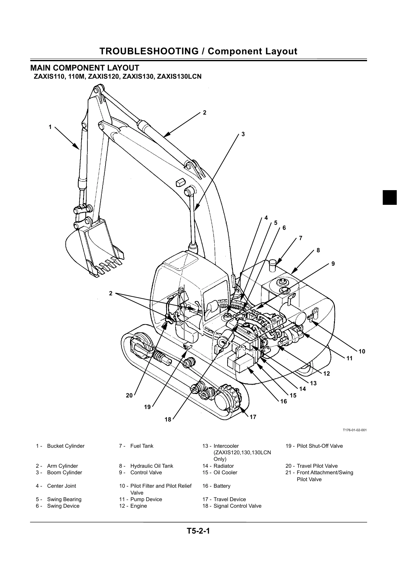
Group 2 Component Layout provides the main component layout, electrical component layout, relay and related equipment layout, monitor and switch layouts, pump device layout, swing device, signal control valve, control valve, solenoid valve unit, 8-unit solenoid valve unit, travel device, and blade control valve layouts for each model group.
Group 3 Troubleshooting A provides fault-code-based diagnostics for the main controller. It covers fault codes for abnormal EEPROM, abnormal RAM, abnormal A/D conversion, abnormal sensor voltage, abnormal EC sensor, abnormal engine control dial angle, abnormal pump 1 and pump 2 delivery pressures, abnormal pump 1 and pump 2 control pressures, abnormal swing/boom raise/arm roll-in/travel pilot pressures, and abnormal oil temperature. Each fault code has a complete flow chart with connector terminal references.
Group 4 Troubleshooting B covers base machine diagnosis starting from abnormal operational status when no fault codes are displayed. It includes relationship tables between trouble symptoms and related parts, engine system troubleshooting (starter doesn’t rotate, engine doesn’t start, engine stalls, engine speed remains unchanged, engine speed doesn’t increase, faulty HP mode, engine doesn’t stop, faulty auto-idle, faulty E mode, faulty auto-acceleration, engine hunts, attachment mode speed issues, engine stalls at high altitude, difficult cold starting), all-actuator system troubleshooting, front attachment system troubleshooting, swing system troubleshooting, travel system troubleshooting, blade system troubleshooting, and other system troubleshooting including wiper and air conditioner issues. The air conditioner troubleshooting includes the self-diagnosis function with fault codes for the circulation air sensor, fresh air sensor, solar radiation sensor, evaporator sensor, water temperature sensor, air vent damper, air mix damper, circulation/fresh air damper, and refrigerant pressure.
Group 5 Troubleshooting C covers monitor diagnosis for malfunctioning gauges and indicators including coolant temperature gauge, fuel gauge, indicator light check system, preheat indicator, engine oil level indicator, coolant level indicator, alternator indicator, engine oil pressure indicator, overheat indicator, air filter restriction indicator, buzzer, LCD, hour meter, and hydraulic oil filter indicator.
Group 6 Troubleshooting D covers the Auto-MARCCINO front attachment control system for the ZAXIS135UR. It includes fault code lists for the Auto-MARCCINO controller with corresponding system monitor displays, buzzer sounds, and system indicator states, plus troubleshooting flow charts for communication faults, metering correction value faults, calibration value faults, arm roll-out/right offset/left offset/boom raise function faults, pilot pressure sensor faults, proportional solenoid valve faults, angle sensor faults, sensor deviation faults, initial setting faults, oil temperature sensor faults, sensor power source faults, and reference power source faults.
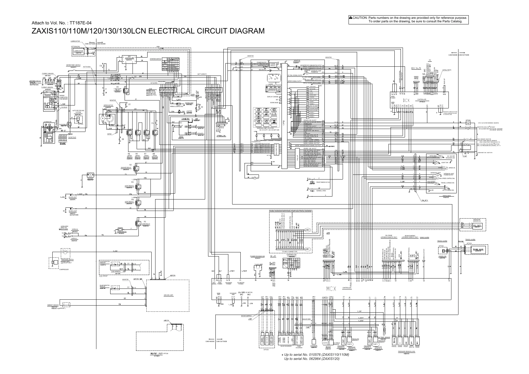
Group 7 Electrical System Inspection provides precautions for inspection and maintenance, instructions for disconnecting connectors, fuse inspection, fusible link inspection, battery voltage check, alternator malfunction troubleshooting, continuity checks (single-line and multi-line, both continuity and short-circuit), voltage and current measurement for the 24-volt circuit, 5-volt circuit checks, and test harness information.
Group 8 ICX covers the information controller, including the daily report data list, frequency distribution data list, cumulative operation hour list, alarm list, trouble list, ICX fault code list, satellite terminal fault code list, fault code troubleshooting for codes 1 through 10, and procedures for downloading from and uploading to the ICX.
Covered Models
The procedures in this manual apply to the following Hitachi Zaxis excavator models:
- ZAXIS110
- ZAXIS110M
- ZAXIS120
- ZAXIS130
- ZAXIS130LCN
- ZAXIS125US
- ZAXIS135US
- ZAXIS135UR
Where procedures or values differ between models, the manual provides separate performance standard tables and reference values for each model group. For example, the ZAXIS110/110M/125US/135UR share one set of P-Q line points while the ZAXIS120/130/130LCN/135US use a different set. The injection pump test conditions also differ between the ZAXIS110/110M/125US/135UR group and the ZAXIS120/130/130LCN/135US group. Model-specific information is clearly identified throughout.
What This Manual Enables You to Do
This Hitachi Zaxis excavator technical troubleshooting manual gives you the complete diagnostic framework for the ZAXIS110, ZAXIS110M, ZAXIS120, ZAXIS130, ZAXIS130LCN, ZAXIS125US, ZAXIS135US, and ZAXIS135UR. With it you can perform comprehensive operational performance tests to evaluate engine, travel, swing, and hydraulic cylinder performance against factory standard values; diagnose fault codes displayed by the main controller using Dr. ZX or the built-in diagnosing system; follow systematic troubleshooting flow charts for abnormal operational symptoms when no fault codes appear; diagnose monitor gauge and indicator malfunctions; troubleshoot the Auto-MARCCINO front attachment control system on the ZAXIS135UR; inspect the electrical system including fuses, fusible links, batteries, alternators, continuity, and voltage; and work with the ICX information controller data and fault codes.
Having the correct performance standards and diagnostic procedures matters because these machines are complex hydraulic and electronic systems where guesswork leads to misdiagnosis, unnecessary parts replacement, and costly downtime. This manual provides the exact test conditions, switch positions, hydraulic oil temperature requirements, pressure values, flow rates, cycle times, and adjustment procedures needed to correctly evaluate and restore machine performance. The troubleshooting flow charts walk through each possible cause in a logical sequence, from the most probable to the least, with specific connector terminal references, voltage specifications, resistance values, and inspection methods.
The fault code lists cover the full range of main controller diagnostics — EEPROM, RAM, A/D conversion, sensor voltage, EC sensor, engine control dial, pump delivery and control pressures, pilot pressures for swing, boom raise, arm roll-in, and travel, and oil temperature — as well as the Auto-MARCCINO controller codes for the ZAXIS135UR including communication faults, metering and calibration value faults, function faults, pilot pressure sensor faults, proportional solenoid valve faults, angle sensor faults, deviation faults, initial setting faults, oil temperature sensor faults, and power source faults. Each fault code is presented with its Dr. ZX display, system monitor display, buzzer sound, system indicator state, and cause of trouble.
The component layout group provides visual references for locating every major component on the machine — bucket cylinder, arm cylinder, boom cylinder, center joint, swing bearing, swing device, fuel tank, hydraulic oil tank, control valve, pilot filter and pilot relief valve, pump device, engine, intercooler, radiator, oil cooler, battery, travel device, signal control valve, pilot shut-off valve, travel pilot valve, front attachment/swing pilot valve, solenoid valve unit, 8-unit solenoid valve unit, blade control valve, positioning control valve, emergency stop valve, blade pilot valve, offset pilot valve, and offset anti-drift valve — along with the electrical components including the horn, work light, fuel sensor, solenoid valve unit, hydraulic oil temperature sensor, EC motor and EC sensor, engine oil pressure switch, overheat switch, coolant temperature sensor, battery relay, glow plug relay, air cleaner restriction switch, wiper motor, alternator, starter, and all pressure sensors.
Get Instant Access
IMAGES PREVIEW
This Hitachi Zaxis excavator Technical Manual (Troubleshooting) TT187-E-04 is delivered as a PDF download immediately after payment. No shipping, no waiting for a physical book. The 479-page file can be viewed on any device — laptop, tablet, or smartphone — and pages can be printed for use in the workshop. Whether you are a professional heavy equipment technician, a fleet maintenance manager, or an owner-operator who does your own diagnostics and repairs, this manual provides the complete technical information needed to keep your Zaxis excavator running to specification.
Reviews
There are no reviews yet.