
Hitachi Zaxis 160LC-3 180LC-3 180LCN-3 Troubleshooting Technical Manual PDF
Original price was: $39.95.$24.95Current price is: $24.95.
The Hitachi Zaxis 160LC-3, 180LC-3 and 180LCN-3 Troubleshooting Technical Manual in PDF — complete operational performance test procedures, standard value tables, fault code diagnostics and step-by-step troubleshooting flow charts for these hydraulic excavators.
Description
Hitachi Zaxis 160LC-3, 180LC-3 and 180LCN-3 Troubleshooting Technical Manual
This Hitachi Zaxis 160LC-3 180LC-3 180LCN-3 Troubleshooting Technical Manual is the diagnostic half of the technical documentation set for these three hydraulic excavator models. It pairs the complete Operational Performance Test section with the full Troubleshooting section, giving a technician both the measurements that define a healthy machine and the procedures that trace a fault back to its source. Published by Hitachi Construction Machinery Co., Ltd. in Tokyo, the manual carries revision information up to 12 November 2007.
The document is aimed at an experienced technician rather than an operator. It assumes the reader already understands how the machine is built and concentrates on how to prove whether it is performing to specification — and what to inspect, disconnect or measure when it is not.
File Details
- Manual type: Technical Manual (Troubleshooting)
- Brand: Hitachi Construction Machinery
- Models covered: ZAXIS160LC-3, ZAXIS180LC-3, ZAXIS180LCN-3
- Language: English
- File format: PDF
- Page count: 622 pages
- Revision information: Contains revision information to 12 November 2007
- Publisher: Hitachi Construction Machinery Co., Ltd., Tokyo, Japan
Chapters Covered
The manual is divided into two technical sections. Section 4 covers operational performance testing; Section 5 covers troubleshooting.
- Section 4 — Operational Performance Test
- Group 1: Introduction — performance test preparation and test-area precautions
- Group 2: Standard — ZAXIS160LC-3 Operational Performance Standard Table, ZAXIS180LC-3 Operational Performance Standard Table, Main Pump P-Q Diagram, Sensor Activating Range, Adjustment Data List, Attachment Adjustment Data List
- Group 3: Engine Test — engine speed, engine compression pressure, valve clearance, lubricant consumption
- Group 4: Excavator Test — travel speed, track revolution speed, mistrack check, travel parking leakage, swing speed, swing function drift check, swing motor leakage, maximum swingable slant angle, swing bearing play, hydraulic cylinder cycle time, dig function drift check, control lever operating force, control lever stroke, combined operation of boom raise / swing, combined operation of boom raise / arm roll-in
- Group 5: Component Test — primary and secondary pilot pressure, solenoid valve set pressure, main pump delivery pressure, main relief valve set pressure, swing relief pressure, overload relief pressure, main pump flow rate (P-Q control and pilot characteristics), regulator adjustment, swing motor drainage, travel motor drainage
- Group 6: Adjustment — parameter change and attachment parameter change through Dr. ZX
- Section 5 — Troubleshooting
- Group 1: Diagnosing Procedure
- Group 2: Monitor Unit — screen navigation, service menu, monitoring, maintenance settings, language settings, mail and keyless hour meter
- Group 3: e-Shovel — daily report data, frequency distribution data, total operating hours, ICF data download and upload, satellite communication setup and fault codes
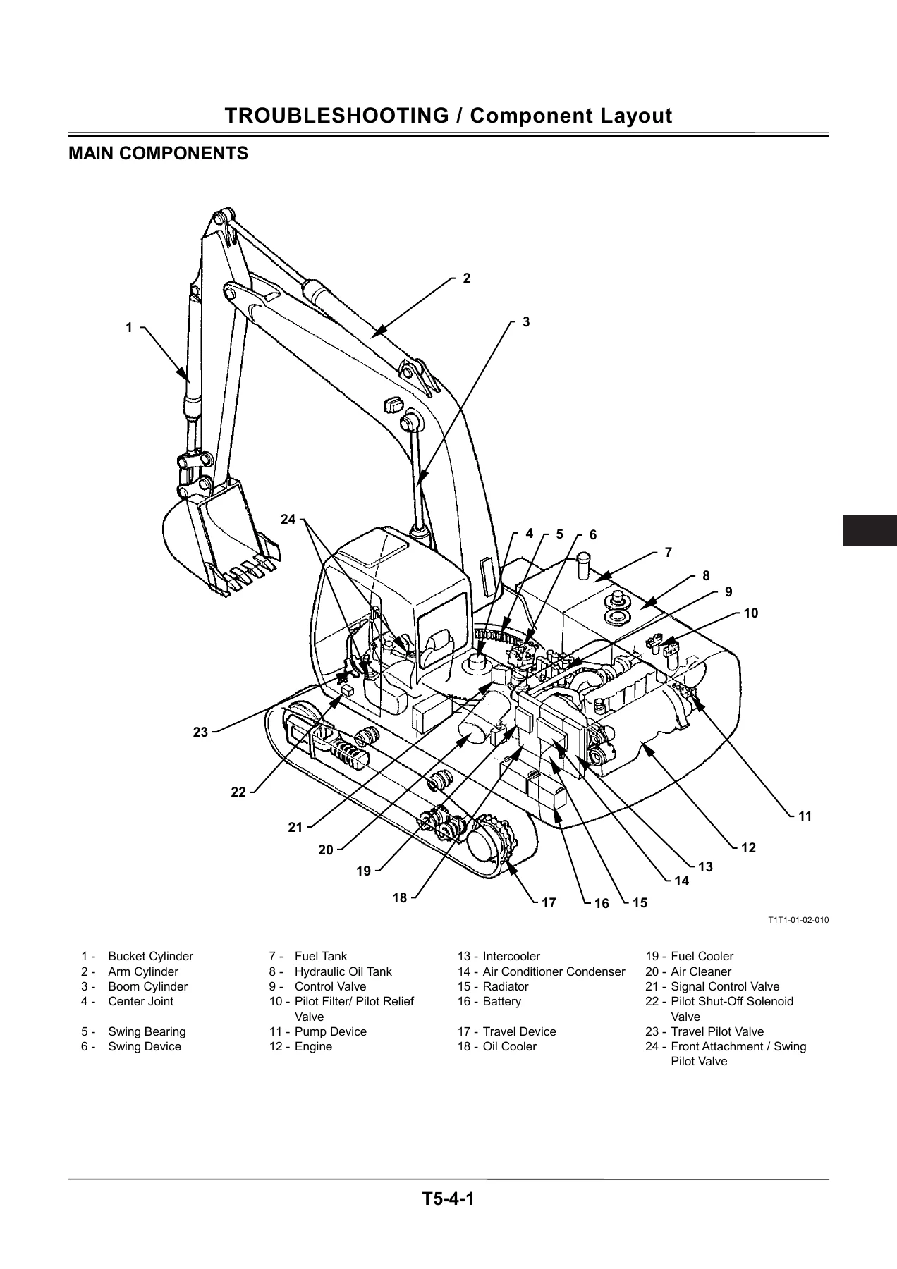
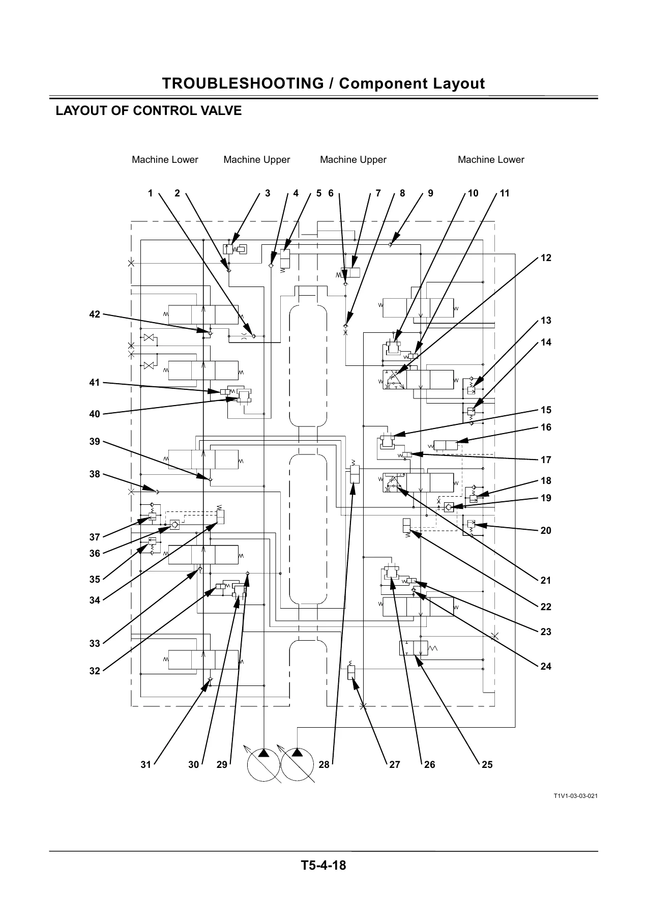
- Group 4: Component Layout — main components, electrical system, engine, pump device, swing device, control valve, signal control valve, solenoid valve unit, travel device, attachment specification parts and pilot ports
- Group 5: Troubleshooting A — fault code diagnosis for MC, ECM, ICF, satellite terminal and monitor unit
- Group 6: Troubleshooting B — symptom-based diagnosis covering engine, all-actuator, front attachment, swing, travel and other systems, plus exchange inspection and emergency boom lowering
- Group 7: Electrical System Inspection — fuse and fusible link inspection, battery voltage check, alternator check, continuity checks, voltage and current measurement, false signal checks and test harnesses
Read together, these groups give a technician a complete diagnostic loop. The performance test groups establish what the machine should do — measured in seconds per 10 m of travel, seconds per three revolutions of swing, millimetres of drift per five minutes, litres per minute of pump delivery and megapascals of relief pressure — while the troubleshooting groups take a reported complaint and work backwards through pressure sensors, proportional solenoid valves, CAN communication lines, spools and seals until the failed component is isolated. The standard value tables are given separately for the ZAXIS160LC-3 and the ZAXIS180LC-3, because travel, swing, cylinder cycle and relief values differ between the two machines.
Fault Code Diagnostics for MC, ECM, ICF and Monitor Unit
Section 5, Group 5 is built around the fault codes each controller stores and reports. The manual lists the trouble, the cause and the control functions affected for every code, then walks through the confirmation procedure. Coverage includes controller hardware failures, engine speed and engine control dial sensor faults, pump delivery and pump control pressure sensor faults, swing, boom raise, arm roll-in, travel and front attachment pilot pressure sensor faults, proportional solenoid valve feedback faults for the torque control valve and the SF, SC, SG and SI solenoid valve units, CAN data reception failures and the harness continuity, short-circuit and discontinuity checks that accompany them.
The troubleshooting A flow charts are written to be followed literally. Each box states an instruction, a reference or an inspection method, and each answer routes the reader to the next box, with the likely causes stated in the thick-line boxes so an experienced technician can scan ahead and form a theory before starting to measure. CAN harness checks are laid out terminal by terminal across the MC, ICF, ECM and monitor unit connectors, including continuity, discontinuity to ground, discontinuity to power and discontinuity to the key signal circuit.
Operational Performance Testing and the Standard Value Tables
The performance test section is what separates this manual from a generic repair guide. It defines the exact switch positions and hydraulic oil temperature for a valid test — fast idle, P mode, auto-idle OFF, digging mode, hydraulic oil at 50 ± 5 °C — and then gives the acceptable result for each measurement. Engine speeds for slow idle, fast idle, E mode, HP mode, auto-idle and warming-up are all specified, as are compression pressure, valve clearance and lubricant consumption. Machine-level tests cover travel speed in fast and slow mode, track revolution speed with the track raised, mistrack over 20 m, swing speed, swing function drift, swing motor leakage on a slope, maximum swingable slant angle, swing bearing play measured with a dial gauge, hydraulic cylinder cycle times, dig function drift with the bucket loaded and control lever operating force and stroke.
Component-level tests then go deeper: primary and secondary pilot pressure, solenoid valve set pressure, main pump delivery pressure at neutral, main relief valve set pressure, swing relief pressure, overload relief pressure and main pump flow rate read against the P-Q curve, plus regulator adjustment procedures with the exact turn-to-pressure relationship for the minimum flow rate, maximum flow rate, pilot pressure characteristics and P-Q torque adjustments. Drain oil measurement procedures for the swing motor and travel motor, including how to convert the collected volume into litres per minute, are included with the test setup shown.
Symptom-Based Troubleshooting When No Fault Code Appears
Group 6 exists for the cases where the controllers report nothing but the machine still behaves wrongly. It opens with tables correlating machine trouble symptoms with the parts that can cause them, and trouble symptoms with part failures, then moves into dedicated flow charts for engine system problems, all-actuator problems, front attachment problems, swing problems, travel problems and other systems. Typical entries include a starter that does not rotate, an engine that will not start, an engine that will not stop on the key switch, faulty HP mode or travel HP mode, faulty auto-idle, E mode that does not reduce engine speed, slow or unmoving swing, one track that does not rotate, mistracking during combined travel and front attachment operation, and a machine that cannot be raised off the ground. Two practical safety procedures close the group: emergency boom lowering and attachment pilot circuit pressure release.
Monitor Unit, Component Layout and Electrical Inspection
Supporting the diagnostics are the monitor unit operating instructions, which explain how to reach the service menu, read monitoring values, display operating conditions, adjust pump 2 flow rate, select attachments, set maintenance intervals and languages, and read the fault code screens. The component layout group shows where every relevant sensor, solenoid valve and controller lives — in the cab, on the rear tray, on the switch panel, around the air cleaner, on the engine, on the pump device, on the swing device, on the control valve, on the signal control valve, on the travel device and in the attachment specification areas — with pilot port tables for the signal control valve. The electrical system inspection group then gives the fuse and fusible link layout with capacities, battery and alternator check procedures, single-line and multi-line continuity and short-circuit checks, voltage and current measurement tables for the 24 V circuits, and the test harness part numbers used with the procedures.
Buy the Hitachi Zaxis 160LC-3 180LC-3 180LCN-3 Troubleshooting Technical Manual
With this Hitachi Zaxis 160LC-3 180LC-3 180LCN-3 Troubleshooting Technical Manual on hand, a technician can run a full performance evaluation of either machine, compare every result against the published standard, pull and interpret fault codes from the main controller, engine controller, information controller and monitor unit, and follow a structured diagnostic path from a reported symptom down to the failed sensor, valve, spool or seal. Correct diagnostic procedure matters on these excavators because the hydraulic and electronic systems are interlinked — a single pressure sensor reading outside its range changes pump control, regeneration and travel behaviour, and guessing at components wastes both time and parts.
IMAGES PREVIEW
Delivery is instant. The file is a downloadable PDF that opens on a laptop, tablet or phone, prints cleanly for the workshop and needs no shipping and no waiting. Start diagnosing the same day.
Reviews
There are no reviews yet.