
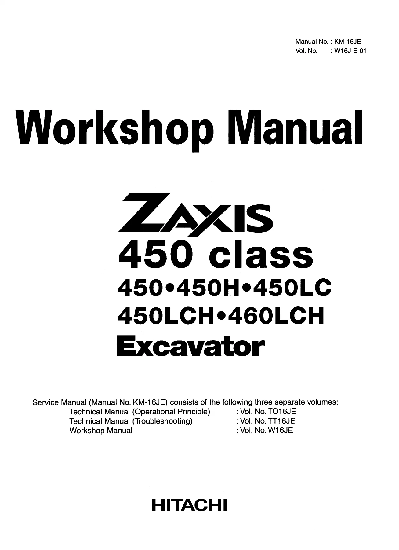
Hitachi Zaxis 450 450H 450LC 450LCH 460LCH Excavator Workshop Manual W16J-E-01
Original price was: $34.95.$21.95Current price is: $21.95.
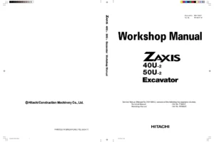
Complete Workshop Manual for the Hitachi Zaxis 450-class excavator series — covering ZAXIS450, 450H, 450LC, 450LCH, and 460LCH models. Vol. No. W16J-E-01 delivers full disassembly, assembly, tightening torque, maintenance standards, and procedural coverage for every major system: upperstructure, undercarriage, front attachment, and engine. Instant PDF download.
Description
File Details
- Manual Type: Workshop Manual
- Vol. No.: W16J-E-01
- Manual No.: KM-16JE
- Brand: Hitachi Construction Machinery Co., Ltd.
- Models Covered: ZAXIS450, ZAXIS450H, ZAXIS450LC, ZAXIS450LCH, ZAXIS460LCH
- Language: English
- Pages: 630
- File Format: PDF
- Publisher: Hitachi Construction Machinery Co., Ltd., Tokyo, Japan
- Copyright: 2004
What This Manual Covers
The Hitachi Zaxis 450 450H 450LC 450LCH 460LCH Excavator Workshop Manual W16J-E-01 is the dedicated repair and maintenance volume within the three-part KM-16JE service manual set. The other two volumes — Technical Manual (Operational Principle, Vol. TO16JE) and Technical Manual (Troubleshooting, Vol. TT16JE) — are separate publications. This Workshop Manual volume focuses entirely on hands-on maintenance and repair: the tools required, maintenance standards, and the step-by-step removal, installation, disassembly, and assembly procedures a shop technician needs to work on these machines correctly.
Section 1 — General Information
- Group 1: Precautions for Disassembling and Assembling
- Group 2: Tightening Torque Specification, Torque Chart, Piping Joint torques, Periodic Replacement of Parts
- Group 3: Painting specification and masking guidance
- Group 4: Bleeding Air from Hydraulic Oil Tank
Section 2 — Upperstructure
- Group 1: Cab — removal, installation, glass dimensions, glass removal and installation
- Group 2: Counterweight — removal and installation (ZAXIS450 and other variants noted separately)
- Group 3: Main Frame — removal and installation
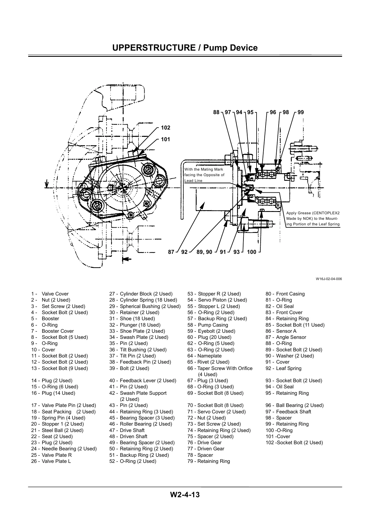
- Group 4: Pump Device — removal and installation, disassembly, assembly, maintenance standards, regulator and pilot pump procedures
- Group 5: Control Valve — removal and installation, disassemble and assemble housing and manifold (5-spool section, 4-spool section, side section)
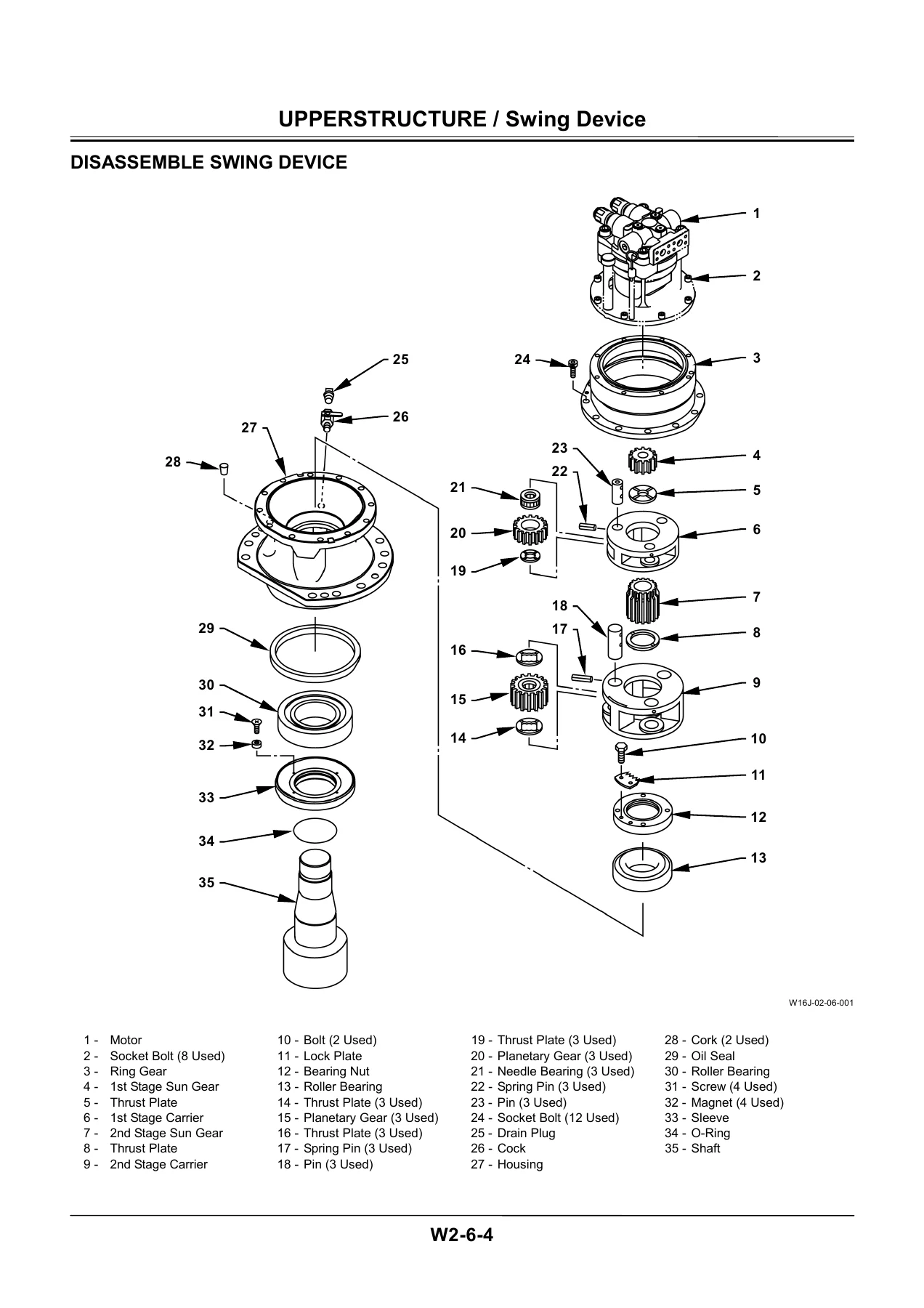
- Group 6: Swing Device — removal and installation, disassembly, assembly, swing motor disassembly and assembly, maintenance standards
- Group 7: Pilot Valve — removal and installation, disassembly and assembly of travel pilot valve
- Group 8: Pilot Shut-Off Valve — removal, installation, and component detail
- Group 9: Signal Control Valve
- Group 10: Solenoid Valve — removal and installation, three-spool solenoid valve detail
- Group 11: Shockless Valve — removal, installation, and component detail
Section 3 — Undercarriage
- Group 1: Swing Bearing — removal and installation
- Group 2: Travel Device — removal, installation, disassembly, assembly, maintenance standards
- Group 3: Center Joint — removal, installation, disassembly, assembly
- Group 4: Track Adjuster
- Group 5: Front Idler
- Group 6: Upper and Lower Roller
- Group 7: Track — removal, installation, and service procedures
Section 4 — Front Attachment
- Group 1: Front Attachment — boom, arm, bucket linkage pin and bushing maintenance standards, side cutter wear limits
- Group 2: Cylinder — boom cylinder, arm cylinder, and bucket cylinder removal, installation, disassembly, and assembly
Section 5 — Engine
The engine section integrates the Isuzu 6WG1TQA service documentation, organized into the following sub-sections:
- General Information — Main Data and Specifications, Performance Curve, Engine External Drawing, Service Standard tables (cylinder head, valvetrain, piston and connecting rod, piston and cylinder liner grade, crankshaft, engine electrical, turbocharger), Torque Specifications, Special Tools, Troubleshooting, Lubricant and Sealant Application
- Service Information — Identification, Lubrication System, Fuel System, Cooling System, Valve Clearance Adjustment, Compression Pressure Measurement, Recommended Lubricants, Oil Viscosity Chart
- Engine Mechanical — Turbocharger, Exhaust Manifold, Inlet Manifold, Water Pump, Alternator, Oil Cooler, Injection Pump, Coupling Assembly, Cylinder Head, Rocker Arm and Shaft Assembly, Camshaft, Timing Gears, Flywheel Housing, Oil Pan, Piston, Crankshaft, Crank Pulley, Flywheel, Cylinder Body
- Engine Cooling — Water Pump, Thermostat disassembly and reassembly
- Engine Fuel — Fuel Filter, Injection Nozzle Holder, Injection Pump
- Starting and Charging — Alternator, Starter Motor
- Engine Lubrication — Oil Pump, Oil Cooler
- Engine Induction — Turbocharger disassembly, inspection and repair, reassembly
Engine Specification Reference
The engine covered in Section 5 is the Isuzu 6WG1TQA: a six-cylinder, 147 mm bore × 154 mm stroke, 15.681-liter turbocharged diesel producing 235.4 kW at 1,800 min⁻¹ rated output and 1,274.9 N·m maximum torque at 1,500 min⁻¹. Compression ratio is 16.4:1. Coolant volume is 36 L; engine oil capacity is 52 L (with combined main and partial filter). This specification data is extracted directly from the Main Data and Specifications table (Section 0A-9 of the engine sub-documentation) included in this volume.
What a Technician Gets from This Manual
The Hitachi Zaxis 450 Workshop Manual W16J-E-01 gives a qualified technician everything needed to perform a full mechanical overhaul of the ZAXIS450-class machines without guesswork. Tightening torque values are organized by fastener grade, thread size, and specific application — critical when reassembling major components like the swing bearing (2,650 N·m), main frame (2,400 N·m), and control valve manifold (245 N·m). Maintenance standards tables specify clearance limits, wear allowances, and service limits for every major assembly: pump cylinder block clearances, swing motor bearing fits, travel device piston-to-shoe clearance (0.4 mm max), front attachment pin diameters and bushing bore allowable limits, and engine piston ring gaps, valve stem diameters, and camshaft bearing clearances.
Disassembly and assembly procedures are broken down into numbered steps with torque callouts, component weight cautions (cab: 300 kg; counterweight: 9,200 kg; control valve: 400 kg; bucket cylinder: 400 kg), special tool references, and matching-mark guidance to prevent assembly errors. The exploded-view illustrations that accompany the pump device, swing device, control valve, and travel device procedures identify every subcomponent, making it practical to track parts through complex multi-stage teardowns.
Periodic replacement intervals for rubber hoses, seals, and other life-limited parts are listed in a dedicated table. The bleeding procedure for the hydraulic system — including the sequence for cycling cylinders after oil drain and pump service — is given explicitly to prevent air-contamination damage after major hydraulic work.
Repair, Rebuild, and Maintenance Applications
Owners, fleet maintenance teams, and independent repair shops working on the Hitachi Zaxis 450 450H 450LC 450LCH 460LCH excavator series will use this manual for: pump device rebuilds (main pump and regulator); swing motor and swing device overhaul; travel device three-stage planetary gear teardown; control valve disassembly and spool service; cylinder seal replacement and rod inspection; engine top-end and bottom-end overhaul (the 6WG1TQA); injection pump and nozzle service; alternator and starter motor service; cab and cab glass replacement; counterweight and main frame removal for major structural repair; and hydraulic system air-bleeding after component replacement.
Having correct Hitachi torque specifications and maintenance standards on hand prevents the most common field errors: undertorqued swing bearing bolts, incorrect pump regulator spring preload, and cylinder clearances outside service limits that cause premature component failure. This Hitachi Zaxis 450 class Workshop Manual is the technical foundation for any serious repair work on this machine family.
Delivery and Access
This is an instant PDF download. After purchase, the file is available immediately — no shipping wait, no back-order. Open it on any device: desktop, laptop, tablet, or phone. Print individual sections to keep at the workbench while working on the machine. The Hitachi Zaxis 450 450H 450LC 450LCH 460LCH Workshop Manual W16J-E-01 delivers the full 630-page technical content of the original publication in a single, portable file.
Reviews
There are no reviews yet.