Hitachi Zaxis 40U-2 50U-2 Excavator Workshop Manual – PDF Download (W1M9-E-00)
$34.95 Original price was: $34.95.$21.95Current price is: $21.95.
Complete workshop manual for the Hitachi Zaxis 40U-2 and 50U-2 mini excavators. Covers full disassembly, assembly, and maintenance procedures for all major systems — upperstructure, undercarriage, front attachment, and engine. Vol. No. W1M9-E-00, 564 pages, English.
Description
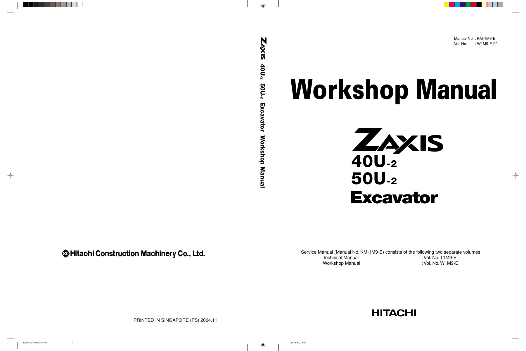
Hitachi Zaxis 40U-2 50U-2 Excavator Workshop Manual — Vol. No. W1M9-E-00
File Details
- Manual Type: Workshop Manual
- Models Covered: Hitachi Zaxis 40U-2, Zaxis 50U-2 Excavators
- Vol. No.: W1M9-E-00
- Manual No.: KM-1M9-E
- Publisher: Hitachi Construction Machinery Co., Ltd., Tokyo, Japan
- Publication Date: 2004.11 (Printed in Singapore)
- Language: English
- Pages: 564
- File Format: PDF
What This Manual Covers
This Hitachi Zaxis 40U-2 50U-2 Workshop Manual is the dedicated repair volume of the two-volume KM-1M9-E service manual set. While the companion Technical Manual (Vol. No. T1M9-E) handles systems theory, operational testing, and troubleshooting, this Workshop Manual focuses exclusively on the hands-on work: the tools, maintenance standards, removal and installation sequences, and disassembly and assembly procedures needed to fully rebuild or repair each major assembly on the machine. It is written for experienced technicians and provides the technical depth a shop-level overhaul demands.
Chapters Covered
- Section 1 — General Information
- Group 1: Precautions for Disassembling and Assembling — shop cleanliness, inspection records, bleeding procedures for hydraulic pump, swing motor, travel motor, and cylinders; floating seal handling; nylon sling precautions
- Group 2: Tightening — torque specifications for Hexagon T, H, and M bolts and socket bolts (M8 through M36); piping joint tightening for union joints, pipe joints, O-ring seal joints, quick couplers, screw-in connections; low-pressure hose clamp torques; hose connection guidelines; periodic replacement intervals for all hydraulic and engine hoses and rubber mounts
- Group 3: Painting — painting colors and surfaces for upperstructure, undercarriage, and front attachment (TAXI yellow, Dark gray SP-424, Black, N-10)
- Group 4: Bleeding Air — procedure for bleeding air from the hydraulic oil tank using a vacuum pump
- Group 5: Floor-Tilting Device — operation, floor tilting-up and tilting-down procedures for canopy and cab configurations (2-pillar and 4-pillar)
IMAGES PREVIEW
- Section 2 — Upperstructure
- Group 1: Canopy — remove and install
- Group 2: Counterweight — remove and install (ZAXIS40U-2: 351 kg / 780 lb; ZAXIS50U-2: 675 kg / 1,490 lb)
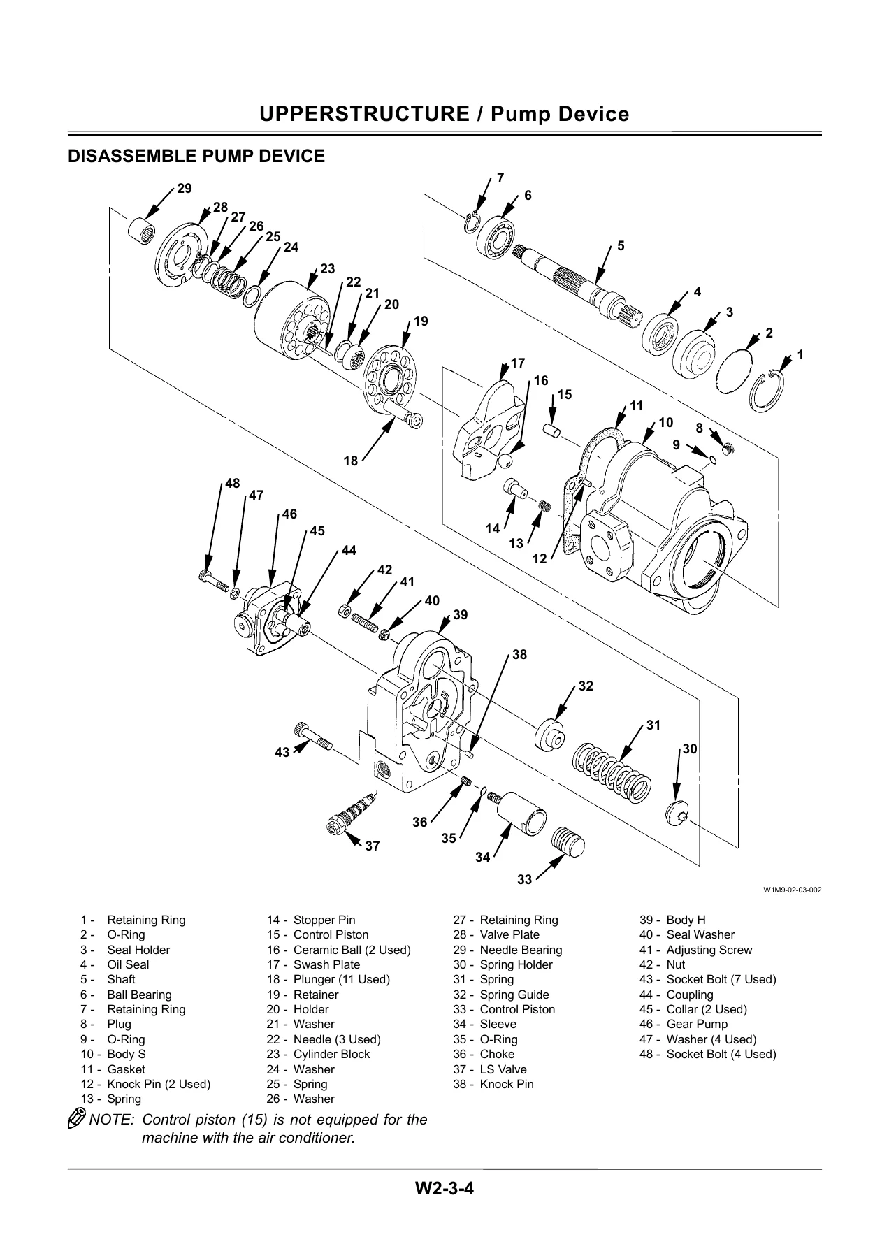
- Group 3: Pump Device — remove, install, disassemble (with full exploded-view diagram of all 48 components), assemble, maintenance standards
- Group 4: Control Valve — remove and install; disassemble/assemble body; remove/install relief valve and make-up valve; disassemble unload section; control valve layout details
- Group 5: Swing Device — disassembly and assembly procedures
- Group 6: Pilot Valve — remove and install front, travel, and blade pilot valves; boom swing pilot valve; disassemble and assemble front pilot valve; disassemble and assemble travel pilot valve; disassemble/assemble pilot valves for boom swing, blade, and auxiliary
- Group 7: Solenoid Valve — remove and install 2-unit solenoid valve; disassemble 2-unit solenoid valve
- Group 8: Revolution Sensing Valve
- Group 9: Auxiliary Flow Selector Valve (Optional)
- Section 3 — Undercarriage
- Group 1: Swing Bearing — remove and install (swing bearing weight: 59 kg / 130 lb)
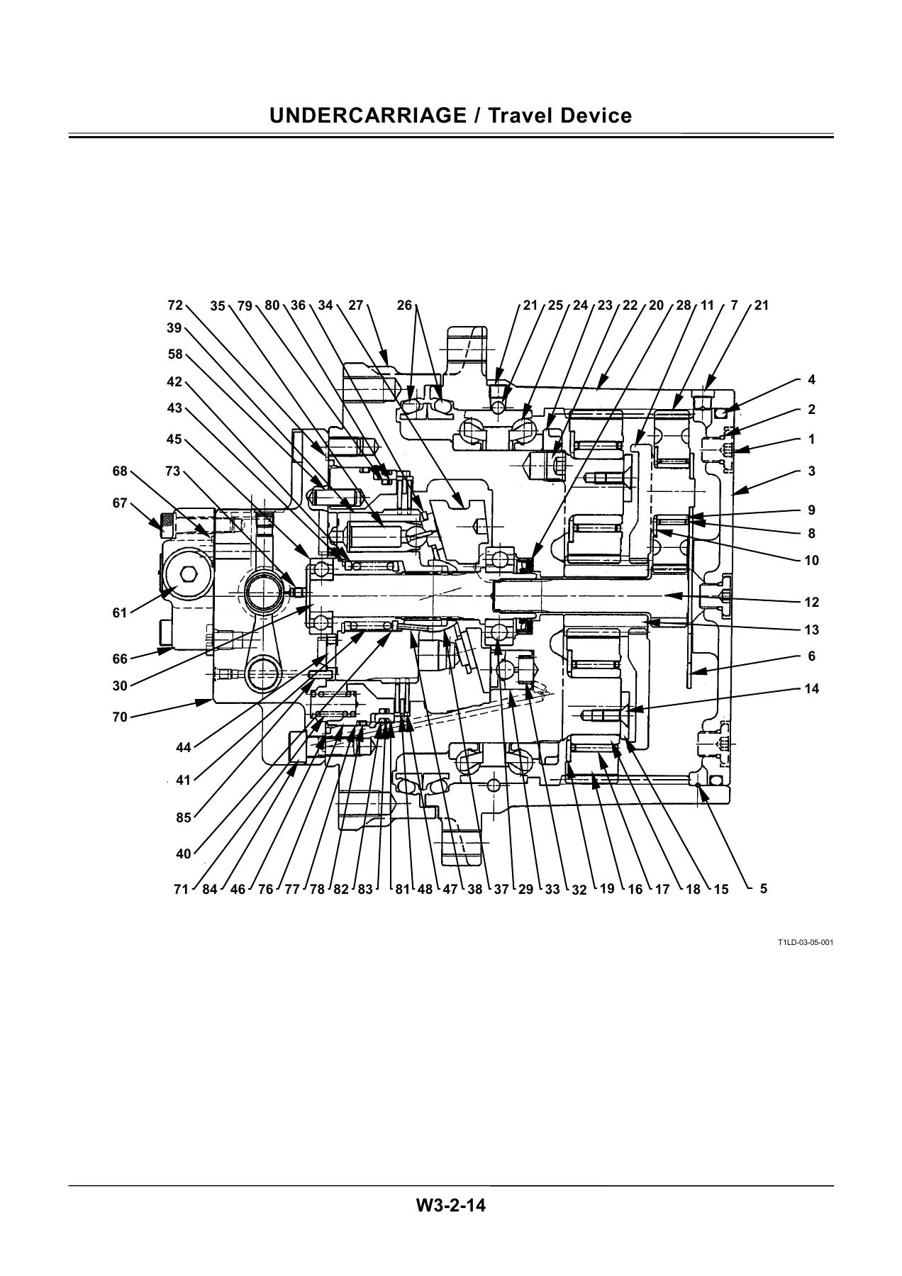
- Group 2: Travel Device — disassembly and assembly with detailed cross-section diagram; 85-component parts list including planetary gears, counterbalance valve, brake valve
- Group 3: Center Joint — disassembly and assembly
- Group 4: Track Adjuster
- Group 5: Front Idler
- Group 6: Upper and Lower Roller — disassemble and assemble
- Group 7: Track
- Section 4 — Front Attachment
- Group 1: Front Attachment — removal, installation, and related procedures
- Group 2: Cylinder — disassembly and assembly of boom, arm, bucket, and swing cylinders
Complete PDF Bookmark TreeComplete Bookmarks
The complete bookmarks in the “Hitachi Zaxis 40U-2 50U-2 Excavator Workshop Manual – PDF Download (W1M9-E-00)” are as follows:
INDEXp. 1INTRODUCTIONp. 3SAFETYp. 5ALL CONTENTSp. 35+SECTION 1 GENERAL INFORMATIONp. 37
+Group 1 Precautions for Disassembling and Assemblingp. 39
Precautions for Disassembling and Assemblingp. 39Maintenance Standard Terminologyp. 45+Group 2 Tighteningp. 47
Tightening Torque Specificationsp. 47Torque Chartp. 48Piping Jointp. 51Periodic Replacement of Partsp. 56+Group 3 Paintingp. 57
Paintingp. 57+Group 4 Bleeding Airp. 59
Bleed Air from Hydraulic Oil Tankp. 59+Group 5 Floor-Tilting Devicep. 61
Floor-Tilting Device Operetion Procedurep. 61Procedure for Floor Tilting upp. 62Procedure for Floor Tilting downp. 64+SECTION 2 UPPERSTRUCTUREp. 69
+Group 1 Canopyp. 71
Remove and Install Canopyp. 71+Group 2 Counterweightp. 73
Remove and Install Counterweightp. 73+Group 3 Pump Devicep. 79
Remove and Install Pump Devicep. 79Disassemble Pump Devicep. 82Assemble Pump Devicep. 84Maintenance Standardp. 88+Group 4 Control Valvep. 89
Remove and Install Control Valvep. 89Disassemble And Assemble Control Valvep. 94Remove and Install Relief Valve and Make-up Valvep. 100Disassemble and Assemble Bodyp. 102Disassemble Unload Sectionp. 104Assemble Unload Sectionp. 106Disassemble and Assemble Spoolp. 108Disassemble and Assemble Boom Anti-Drift Valvep. 110Disassemble and Assemble Shuttle Valve and Pressure Compensation Valvep. 112+Group 5 Swing Devicep. 115
Remove and Install Swing Devicep. 115Disassemble Swing Devicep. 120Assemble Swing Devicep. 122Disassemble Swing Motorp. 128Assemble Swing Motorp. 130Maintenance Standardsp. 134+Group 6 Pilot Valvep. 135
Remove and Install Front Pilot Valvep. 135Remove and Install Travel Pilot Valvep. 137Remove and Install Blade Pilot Valvep. 141Remove and Install Boom Swing Pilot Valvep. 143Disassemble Front Pilot Valvep. 146Assemble Front Pilot Valvep. 150Disassemble Travel Pilot Valvep. 154Assemble Travel Pilot Valvep. 158Disassemble Pilot Valves for Boom Swing, Blade and Auxiliaryp. 164Assemble Pilot Valves for Boom Swing, Blade and Auxiliaryp. 166+Group 7 Solenoid Valvep. 169
Remove and Install 2-Unit Solenoid Valvep. 169Disassemble 2-Unit Solenoid Valvep. 174Assemble 2-Unit Solenoid Valvep. 176Remove and Install 1-Unit Solenoid Valvep. 178Structure of 1-Unit Solenoid Valvep. 180+Group 8 Revolution Sensing Valvep. 181
Remove and Install Revolution Sensing Valvep. 181Disassemble Revolution Sensing Valvep. 184Assemble Revolution Sensing Valvep. 186+Group 9 Auxiliry Flow Selector Valve (Optional)p. 189
Remove and Install Auxiliary Flow Selector Valvep. 189Disassemble Auxiliary Flow Selector Valvep. 192Assemble Auxiliary Flow Selector Valvep. 194+SECTION 3 UNDERCARRIAGEp. 199
+Group 1 Swing Bearingp. 201
Remove and Install Swing Bearingp. 201+Group 2 Travel Devicep. 203
Remove and Install Travel Devicep. 203Disassemble Travel Devicep. 206Assemble Travel Devicep. 214Disassemble and Assemble Brake Valvep. 222Maintenance Standardp. 224+Group 3 Center Jointp. 227
Remove and Install Center Jointp. 227Disassemble Center Jointp. 230Assemble Center Jointp. 232+Group 4 Track Adjusterp. 235
Remove and Install Track Adjusterp. 235Disassemble Track Adjusterp. 236Assemble Track Adjusterp. 242+Group 5 Front Idlerp. 247
Remove and Install Front Idlerp. 247Disassemble and Assemble Front Idlerp. 248Maintenance Standardp. 250+Group 6 Upper and Lower Rollerp. 251
Remove and Install Upper Rollerp. 251Remove and Install Lower Rollerp. 253Disassemble and Assemble Lower Rollerp. 256Maintenance Standardp. 258+Group 7 Trackp. 261
Remove and Install Rubber Trackp. 261Maintenance Standardp. 263+SECTION 4 FRONT ATTACHMENTp. 267
+Group 1 Front Attachmentp. 269
Remove and Install Front Attachmentp. 269Maintenance Standardsp. 274+Group 2 Cylinderp. 277
Remove and Install Cylindersp. 277Disassemble Boom Cylinderp. 290Assemble Boom Cylinderp. 294Disassemble Arm Cylinderp. 300Assemble Arm Cylinderp. 304Disassemble Bucket Cylinderp. 310Assemble Bucket Cylinderp. 314Disassemble Boom Swing Cylinderp. 320Assemble Boom Swing Cylinderp. 324Disassemble Blade Cylinderp. 330Assemble Blade Cylinderp. 334Maintenance Standardsp. 340+SECTION 5 ENGINE AND ACCESSORYp. 343
PREFACEp. 345SAFETY LABELSp. 346CONTENTSp. 354+1. Generalp. 359
1.1 Engine nomenclaturep. 3591.2 Specificationsp. 359+1.3 Fuel oil, lubricating oil and cooling waterp. 372
1.3.1 Fuel oilp. 3721.3.2 Lubricating oilp. 3741.3.3 Cooling waterp. 3751.4 Engine external viewsp. 3761.5 Structural descriptionp. 377+1.6 Exhaust gas emission regulationp. 378
1.6.1 The emission standard in USAp. 3781.6.2 Engine identificationp. 3791.6.3 Guarantee conditions for the EPA emission standardp. 380+2. Inspection and adjustmentp. 382
2.1 Periodic maintenance schedulep. 382+2.2 Periodic inspection and maintenance procedurep. 383
2.2.1 Check before daily operationp. 3832.2.2 inspection after initial 50 hours operationp. 3852.2.3 Inspection every 50 hoursp. 3882.2.4 Inspection every 250 hours or 3 monthsp. 3922.2.5 Inspection every 500 hours or 6 monthsp. 3952.2.6 Inspection every 1,000 hours or one yearp. 3972.2.7 Inspection every 2000 hours or 2 yearsp. 4062.3 Adjusting the no-load maximum or minimum speedp. 410+2.4 Sensor inspectionp. 411
2.4.1 Oil pressure switchp. 4112.4.2 Thermo switchp. 4112.5 Water leak check in cooling water systemp. 4112.6 Radiator cap inspectionp. 4122.7 Thermostat Inspectionp. 4122.8 Adjusting operationp. 4132.9 Long storagep. 413+3. Troubleshootingp. 414
3.1 Preparation before troubleshootingp. 4143.2 Quick reference table for troubleshootingp. 4153.3 Troubleshooting by measuring compression pressurep. 418+4. Disassembly, inspection and reassembly of enginesp. 420
+4.1 Complete disassembly and reassemblyp. 420
4.1.1 Introductionp. 4204.1.2 Special service toolsp. 4214.1.3 Complete disassemblyp. 4264.1.4 Precautions before and during reassemblyp. 4304.1.5 Adjusting operationp. 430+4.2 Cylinder head: Disassembly, inspection and reassemblyp. 431
4.2.1 Components (2-valve cylinder head)p. 4314.2.2 Disassembly procedure:p. 4314.2.3 Reassembly procedure:p. 4324.2.4 Servicing pointsp. 4334.2.5 Parts Inspection and measurementp. 4374.2.6 Valve seat correctionp. 4414.2.7 Valve guide replacementp. 4424.2.8 Valve stem seal replacementp. 443+4.3 Gear train and camshaftp. 444
4.3.1 Componentsp. 4444.3.2 Disassembly procedure:p. 4444.3.3 Reassembly procedure:p. 4444.3.4 Servicing pointsp. 4454.3.5 Parts inspection and measurementp. 4484.3.6 Oil seal replacement (Gear case side)p. 4504.3.7 Camshaft bushing replacementp. 450+4.4 Cylinder blockp. 451
4.4.1 Componentsp. 4514.4.2 Disassembly procedure:p. 4514.4.3 Reassembly procedure:p. 4514.4.4 Servicing pointsp. 4524.4.5 Parts inspection and measurementp. 4564.4.6 Cylinder bore correctionp. 4674.4.7 Piston pin bushing replacementp. 4684.4.8 Oil seal replacement (Flywheel housing side)p. 468+5. Lubrication systemp. 469
5.1 Lubrication system diagramp. 4695.2 Trochoid pump componentsp. 4705.3 Disassembly (Reverse the procedure below for assembly)p. 4705.4 Servicing pointsp. 470+5.5 Parts Inspection and measurementp. 471
5.5.1 Trochoid pump inspection and measurementp. 471+6. Cooling systemp. 473
6.1 Cooling water systemp. 4736.2 Cooling water pump componentsp. 4736.3 Disassembly (Reverse the procedure below for assembly)p. 4746.4 Servicing pointsp. 474+7. Fuel injection pump / Governorp. 475
7.1 Introductionp. 475+7.2 Fuel injection pumpp. 475
7.2.1 Fuel system diagramp. 4757.2.2 External view and componentsp. 4767.2.3 Disassembly procedure:p. 4767.2.4 Assembly procedurep. 4777.2.5 Servicing pointsp. 4777.2.6 C.S.D. (Cold Start Device)p. 478+8. Turbocharger: Disassembly, inspection and reassemblyp. 479
+8.1 Structure and functionsp. 479
8.1.1 Main specificationsp. 4798.1.2 Constructionp. 4798.1.3 Structural and functional outlinep. 4808.1.4 Componentsp. 481+8.2 Service standards and tightening torquep. 482
8.2.1 Service standardsp. 4828.2.2 Tightening torquep. 483+8.3 Periodic inspection procedurep. 484
8.3.1 Periodic inspection intervalsp. 4848.3.2 Inspection procedurep. 4858.3.3 Waste gate valve adjustment procedurep. 486+8.4 Disassembly procedurep. 488
8.4.1 Preparation for disassemblyp. 4888.4.2 Inspection before disassemblyp. 4898.4.3 Disassemblyp. 489+8.5 Washing and inspection procedurep. 491
8.5.1 Washingp. 4918.5.2 Inspection procedurep. 492+8.6 Reassembly procedurep. 495
8.6.1 Preparation for reassemblyp. 4958.6.2 Reassemblyp. 495+8.7 Handling after disassembly and reassemblyp. 498
8.7.1 Instructions for turbocharger installationp. 498+8.8 Troubleshootingp. 499
8.8.1 Excessively exhaust smokep. 4998.8.2 White smoke generationp. 4998.8.3 Sudden oil decreasep. 5008.8.4 Decrease in outputp. 5008.8.5 Poor (slow) response (starting) of turbochargerp. 5008.8.6 Abnormal sound or vibrationp. 500+9. Starting motrorp. 501
+9.1 For 4TNV94L/ 98p. 501
9.1.1 Specificationsp. 5019.1.2 Componentsp. 5029.1.3 Troubleshootingp. 5039.1.4 Names of parts and disassembly procedurep. 5049.1.5 Inspection and maintenancep. 5089.1.6 Service standardsp. 5139.1.7 Assemblyp. 5149.1.8 Characteristic testp. 516+9.2 For 4TNV106 (T)p. 517
9.2.1 Specificationsp. 5179.2.2 Congiguration drawingp. 5179.2.3 Troubleshootingp. 5189.2.4 Component names and disassembly procedurep. 5199.2.5 Disassembly procedurep. 5209.2.6 Inspection and maintenancep. 5289.2.7 Assemblyp. 5349.2.8 Adjustmentp. 5359.2.9 Service standardsp. 536+10. Alternatorp. 537
+10.1 The 40A alternator for 3TNV84 and other modelsp. 537
10.1.1 Componentsp. 53710.1.2 Specificationsp. 53810.1.3 Wiring diagramp. 53810.1.4 Standard output characteristicsp. 53910.1.5 Inspectionp. 53910.1.6 Troubleshootingp. 540+11. Electric wiringp. 542
11.1 Electric wiring diagramp. 542+11.2 Precaution on electric wiringp. 543
11.2.1 Alternatorp. 54311.2.2 Starterp. 54411.2.3 Current limiterp. 54511.2.4 Section area and resistance of electric wirep. 546+12. Service standardsp. 547
12.1 Engine tuningp. 547+12.2 Engine bodyp. 548
12.2.1 Cylinder headp. 54812.2.2 Gear train and camshaftp. 55112.2.3 Cylinder blockp. 55212.3 Lubricating oil system (Trochoid pump)p. 557+13. Tightening torque for bolts and nutsp. 558
13.1 Tightening torques for main bolts and nutsp. 55813.2 Tightening torques for standard bolts and nutsp. 559SERVICE MANUAL REVISION REQUEST FORMp. 563 - Section 5 — Engine and Accessory
- Engine nomenclature, specifications, and external views for the Yanmar 4TNV94L (4-cylinder, 94 × 110 mm bore/stroke, 3.054 L displacement, direct injection, water-cooled diesel)
- Structural description and exhaust emission regulation information
- Periodic maintenance schedule and step-by-step inspection procedures (50-hour, 250-hour, 500-hour, 1000-hour, 2000-hour intervals)
- Fuel, lubricating oil, and cooling water specifications; applicable fuel (Diesel oil ISO 8217 DMA, BS 2869 A1/A2, Cetane No. 45 min.) and lubricant (API grade CD or CF) grades
- Engine body: cylinder head disassembly and reassembly; valve clearance inspection and adjustment; fuel injection nozzle pressure inspection and spray pattern check; fuel injection timing adjustment; crankshaft, bearing, and piston inspection
- Lubrication system: trochoid pump components, disassembly, servicing points, parts inspection and measurement
- Cooling system: cooling water pump components and disassembly
- Starting motor procedures: for 4TNV94L/98 (specifications, components, troubleshooting, disassembly, inspection, service standards, assembly, characteristic test)
- Alternator: 40A alternator components, specifications, and wiring diagram
- Electric wiring diagram and precautions
- Service standards: engine tuning data, engine body clearances and wear limits, lubricating oil system standards, tightening torques for all bolts and nuts
Taken together, this Hitachi Zaxis 40U-2 and 50U-2 Workshop Manual gives a technician every procedure needed to strip and rebuild these compact excavators from the ground up — from bleeding hydraulic circuits correctly before start-up, to torquing a counterweight bolt to the exact specification, to adjusting valve clearances and fuel injection timing on the 4TNV94L engine. The document bridges the full gap between symptom (covered in the Technical Manual) and resolution, delivering the step-by-step sequences, component drawings, and tolerance tables that make correct reassembly possible.
What You Can Do With This Manual
With the Hitachi Zaxis 40U-2 50U-2 Workshop Manual (W1M9-E-00) in hand, a qualified technician can perform pump device overhauls using the detailed exploded-view diagrams, rebuild travel motors and swing devices to manufacturer clearance specifications, replace and correctly torque control valve and pilot valve assemblies, service the Yanmar 4TNV94L engine through every scheduled maintenance interval, and carry out full undercarriage rebuilds covering swing bearings, center joints, idlers, rollers, and tracks. Having the correct specifications and sequences — not best guesses — is what separates a repair that holds from one that comes back. Every torque value, every hose replacement interval, every reassembly caution in this document exists to protect the machine and the technician working on it.
This is an instant PDF download. After payment is confirmed you receive a download link immediately — no waiting, no shipping. The file opens on any device capable of reading PDFs: desktop computers, tablets, smartphones, or dedicated PDF readers. You can also print pages or sections as needed for use in the shop.

What Our Customers Say
🌟 Related Products
Discover more professional manuals for your equipment

New Holland Kobelco E485 Excavator Workshop Manual 604.13.472 - March 2005 PDF

Hitachi Zaxis 450 450H 450LC 450LCH 460LCH Excavator Workshop Manual W16J-E-01


Reviews
There are no reviews yet.