
XCMG XE215C Hydraulic Excavator Workshop Manual PDF Download
Original price was: $39.95.$24.95Current price is: $24.95.
XCMG XE215C hydraulic excavator workshop manual covers structure, test procedures, fault diagnosis, torque tables and full disassembly-reassembly for the 320-page service document.
Description
XCMG XE215C Hydraulic Excavator Workshop Manual Overview
This 320-page workshop manual from Xuzhou XCMG Excavator Machinery Co., Ltd. supplies the technical data, maintenance standards, tools, disassembly and re-assembly procedures required for the XE215C hydraulic excavator (overall machine part number 310703524, PIN 4th digit 0). Prepared for experienced technical staff, it details every major system so repairs and adjustments can be performed correctly the first time.
File Details
- Manual type: Workshop / Service Manual
- Brand / Model: XCMG XE215C
- Language: English
- Page count: 320
- File format: PDF
- Version: XE215C Hydraulic Excavator Workshop Manual B-00
Models and Equipment Covered
The manual applies specifically to the XE215C sales model with overall machine part number 310703524 and the 4th digit of the PIN equal to 0. Engine reference throughout the document is the 6BG1 diesel, including injection timing data of 10.4° before top dead center and valve-clearance adjustment procedures.
Chapters and Contents Covered
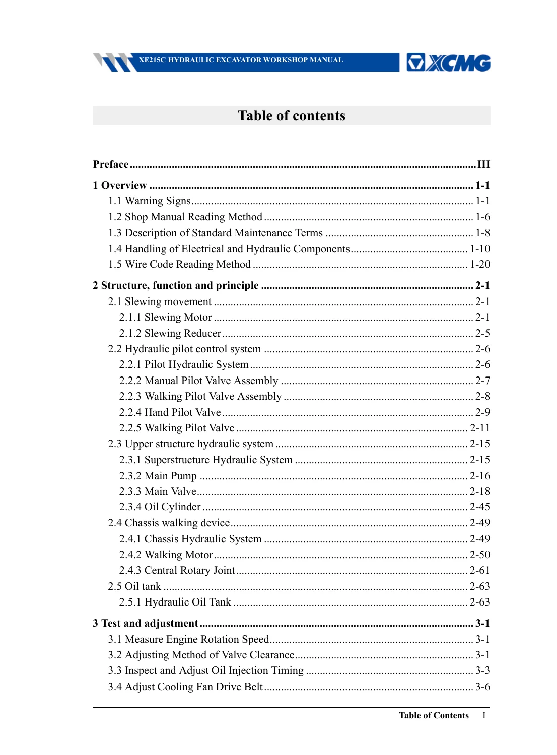
- 1 Overview – Warning signs, shop manual reading method, standard maintenance terms, handling of electrical and hydraulic components, wire code reading method
- 2 Structure, function and principle
- 2.1 Slewing movement (Slewing Motor, Slewing Reducer)
- 2.2 Hydraulic pilot control system (Pilot Hydraulic System, Manual Pilot Valve Assembly, Walking Pilot Valve Assembly, Hand Pilot Valve, Walking Pilot Valve)
- 2.3 Upper structure hydraulic system (Superstructure Hydraulic System, Main Pump, Main Valve, Oil Cylinder)
- 2.4 Chassis walking device (Chassis Hydraulic System, Walking Motor, Central Rotary Joint)
- 2.5 Oil tank (Hydraulic Oil Tank)
- 3 Test and adjustment – Engine rotation speed, valve clearance, oil injection timing, cooling fan belt, compression pressure, exhaust smoke intensity, fuel system leakage, pilot pressure, neutral unloading pressure, main pressure, cylinder relief pressures, slewing and walking relief pressures, cylinder leakage, rotary and walking motor leakage, cylinder settlement, single movement speeds, walking deviation, slewing bearing clearance, track tension, air-conditioner compressor belt, residual hydraulic pressure release
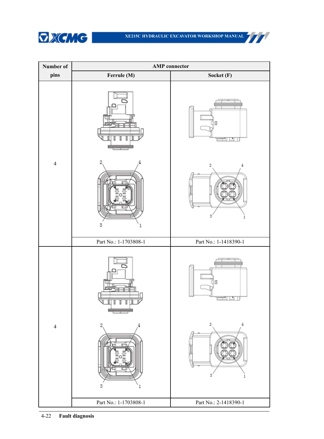
- 4 Fault diagnosis – Overview and notices, connector pin tables, troubleshooting tables for engine / hydraulic / electrical systems, machine and engine fault-code lists with analytic tables
- 5 Moment and tools standard value table – Tightening methods, universal mounting torque table, key-position torque table, special-material torque table
- 6 Disassembly and re-assembly – Hydraulic pump assembly, control valve assembly, swing/slewing motor assembly, walking motor assembly, hydraulic cylinder assemblies (boom, bucket rod, bucket), central rotary joint, working-device pilot valve, traveling pilot valve, hydraulic tank assembly
Systems and Subjects Included
Full coverage of the slewing system (motor and reducer), pilot hydraulic circuit and both hand and walking pilot valves, main pump and main control valve, boom / arm / bucket cylinders, walking motors and central rotary joint, and the hydraulic oil tank (approximately 220 L capacity). Electrical connector pin-outs, wire-code conventions, and controller handling precautions are documented in detail. Safety warnings, lifting procedures, and steel-rope selection tables appear throughout.
Work the Manual Supports
Technicians can measure and adjust engine speed, valve clearance and injection timing on the 6BG1 engine; test pilot, main, relief and neutral-unloading pressures; inspect cylinder and motor leakage; measure track tension and slewing-bearing clearance; release residual hydraulic pressure safely; diagnose faults by symptom tables or by fault codes (A101–A109 hydraulic, A301+ engine, A501+ electrical, E0010–E0060 GPS locking codes); and perform complete disassembly and re-assembly of every major hydraulic and mechanical assembly listed above, using the supplied torque values and special-tool notes.
Specification and Reference Data
- Hydraulic oil tank capacity: about 220 L
- Injection timing (6BG1): 10.4° BTDC
- Valve clearance gauge reference: 0.40 mm
- Extensive torque tables for carbon-steel, alloy-steel, hose-flange and key-position fasteners
- Rotary-joint starting torque 200 N·m / continuous 150 N·m
- Multiple pressure-test conditions referenced to hydraulic-oil temperature of 55 ± 5 °C
Safety and Operational Notices
Chapter 1 details workshop safety rules including correct work clothing, eye protection for grinding and hammering, welder PPE, parking and blocking procedures, residual-pressure release before opening any circuit, battery negative-terminal disconnect order, crane and steel-rope selection tables with permissible loads for 10 mm to 60 mm rope, and bridge-crane operating rules. Lifting a component heavier than 25 kg requires a crane and a weight label on the part.
Electrical Component Handling
Detailed instructions cover connector lock/unlock sequences, prevention of water and oil contamination on pins, DT 8-pin and 12-pin latch engagement, controller protection from rain or mud, and arc-welding ground-wire placement. Wire codes follow TXL (SAE) and FLRY-B (DIN) standards with default 0.75 mm² cross-section, red for power and black for ground.
Hydraulic Cleanliness Rules
The manual stresses dust-free disassembly environments, sealing of open ports with covers or polythene bags, hot-oil change to flush sediment, double flushing after major repairs, and the use of oil-cleaning devices capable of removing particles around 3 µm. On-site repairs of precision components are discouraged in favour of assembly-unit replacement.
Get the Manual and Start Working
With this workshop manual you can measure engine compression and injection timing, set correct pilot and main relief pressures, diagnose A- and E-series fault codes on the instrument panel, and fully disassemble and reassemble the main pump, control valve, swing motor, travel motors and cylinders using the published torque and procedure data. Correct specifications and step-by-step sequences keep the XE215C running reliably and prevent repeat work caused by incorrect adjustments or missed safety steps. Instant PDF download is available the moment payment completes—no shipping delay—readable on any phone, tablet, laptop or workshop PC and printable for bench use.
Reviews
There are no reviews yet.