★ TRUSTED BY 321,897+ PROFESSIONALS WORLDWIDE
🏢
Trusted Business
Verified & Licensed
🛡️
Virus Free Files
100% Safe Downloads
🔒
Secure Payment
SSL Protected
Instant Delivery
Available Immediately
Sale!

Kubota U30-6S Mini Excavator Workshop Manual 2021 WSM PDF

Original price was: $36.95.Current price is: $21.95.

Workshop manual for the Kubota U30-6S mini excavator covering canopy and cabin machines with rubber or steel tracks. Includes safety, maintenance intervals, machine-body repairs, hydraulic and electrical servicing, and cabin air-conditioning procedures from the June 2021 WSM.

Instant PDF Download
Available immediately
💾
Save to Your Device
Download & keep forever
🛡️
Antivirus Scanned
100% virus-free
🌍
Trusted Worldwide
175,000+ customers

Description

Kubota U30-6S Mini Excavator Workshop Manual 2021 WSM PDF

The Kubota U30-6S Mini Excavator Workshop Manual 2021 WSM PDF is the machine-level workshop document issued for the U30-6S compact excavator. It walks a technician from safety and identification through scheduled maintenance, body and undercarriage work, engine R&R on the machine, load-sensing hydraulics, electrical diagnosis, and cabin climate service. The text distinguishes canopy and cabin builds and rubber versus steel track machines, and it points engine internal overhaul to the separate 03-M-DI-E2B series engine workshop manual.

File Details

  • Manual type: Workshop manual (WSM)
  • Brand / model: Kubota excavator U30-6S
  • Language: English
  • Page count: 585
  • File format: PDF
  • Issue: KiSC issued 06, 2021 A
  • Publication date: June 2021
  • Copyright: Kubota Corporation

Machine Coverage in This WSM

General machine information identifies the excavator from the model plate, 17-digit product identification number, five-digit serial number, and engine number. Canopy machines use engine D1803-M-DI-E2-BH-TH1; cabin machines use D1803-M-DI-E2-BH-TH2. Both are water-cooled three-cylinder four-cycle diesels with 1826 cm³ displacement. Rated output is listed as 19.7 kW net SAE J1349 and 20.5 kW net ISO 8178 / ISO 9249 and gross SAE J1995 at 2200 min⁻¹. Idle is 1150 min⁻¹ on canopy units and 1300 min⁻¹ on cabin units.

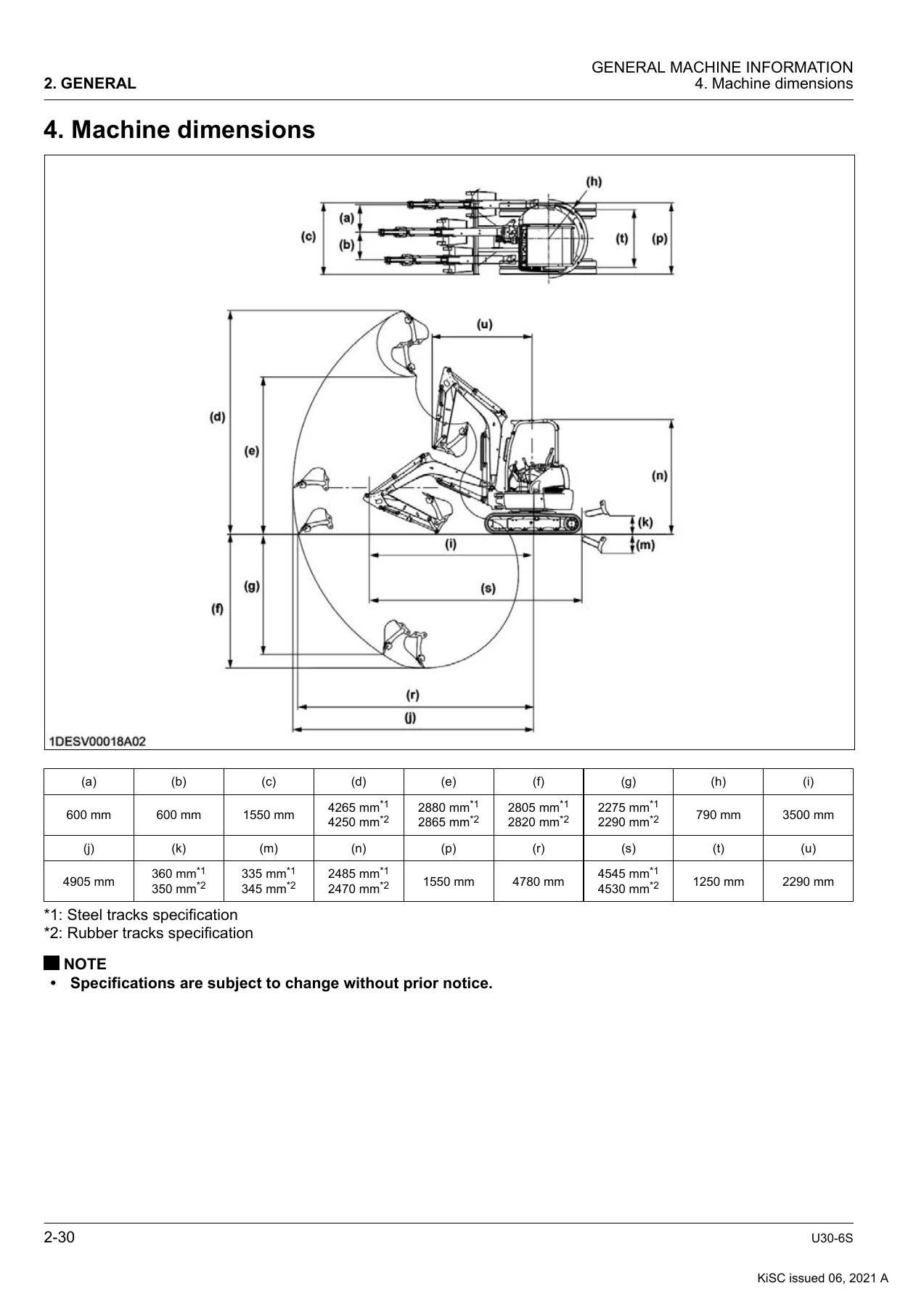
Operating weight with a 75 kg operator and the standard 0.09 m³ / 524 mm bucket runs from 3170 kg (canopy, rubber tracks) to 3440 kg (cabin, steel tracks). Travel is two-speed, swivel speed is 8.6 min⁻¹, climbing performance is given as 58% / 30°, AUX theoretical flow is 50.0 L/min at 20.6 MPa, and the fuel tank is 41.5 L. Dimension drawings separate steel-track and rubber-track figures for overall length, height, tail swing, and digging envelope.

Chapters Covered

  • 1. Safety — safe operation before, during, and after work; ROPS and OPG; loading and transport; maintenance precautions; safety labels
  • 2. General — working instructions, tightening torques, machine and engine identification, specifications, dimensions, mass table, electrical conventions, transport, special jigs and tools
  • 3. Maintenance — interval table, lubricant quantities and recommended fluids, daily through 3000-hour and yearly/two-year tasks, cabin A/C maintenance
  • 4. Machine body — layout and dimensions for bucket, arm, boom, blade, tracks, idler, sprocket, rollers; service specs and play/clearance tests; removal of attachments, cabin/canopy, seat, levers, swivel bearing, tracks, idler, tensioner, rollers
  • 5. Engine — device layout, specifications, dimensions, performance curves; troubleshooting; compression and oil-pressure tests; fuel tank and hose routing; engine, alternator, starter, injection nozzle, radiator, and muffler R&R
  • 6. Hydraulic system — load-sensing and pilot control descriptions; pump, control valve, swivel and travel motors, cylinders, swivel joint, pilot and travel valves, unload, multi, and third-line valves; troubleshooting; speed, leakage, P-Q, relief, and drain tests; full disassembly and adapter layouts; hose routing
  • 7. Electrical system — device, switch, fuse, relay, communication-port, and ground layouts; functional circuits; meter panel, user and service-dealer modes; troubleshooting and error handling
  • 8. Air conditioning and heater system — compressor, A/C unit, condenser, receiver, pressure switch; refrigerant pressure and clutch-gap tests; component R&R and hose routing
  • 9. Appendices — collected service specifications, hydraulic circuit diagram, wire harness, and mode flow charts

IMAGES PREVIEW

Kubota U30-6S Mini Excavator Workshop Manual 2021 WSM PDF — PDF page 1 preview
Kubota U30-6S Mini Excavator Workshop Manual 2021 WSM PDF — PDF page 66 preview
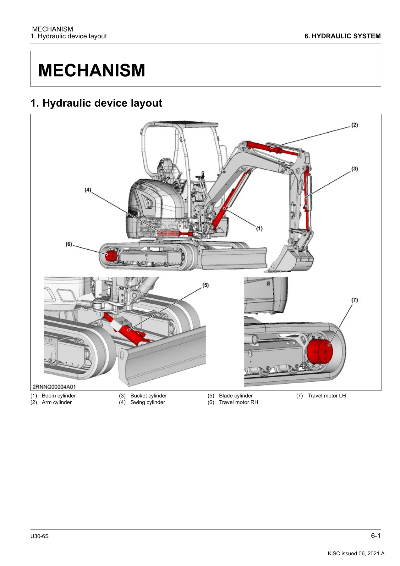
Kubota U30-6S Mini Excavator Workshop Manual 2021 WSM PDF — PDF page 231 preview

Taken together, the Kubota U30-6S Mini Excavator Workshop Manual 2021 WSM PDF is a complete chassis-and-systems workshop book: how each major assembly works, how to test it against printed service specifications and limits, and how to take it apart and put it back together with the listed torques and special tools. Engine short-block overhaul is not duplicated here; the supplementary page sends that work to WSM 03-M-DI-E2B SERIES, PDF No. 9Y011-0286△.

Service Intervals and Fluids

Daily work covers coolant, fuel, engine oil, hydraulic oil, fan belt, coolers, wiring, and greasing. Every 50 hours the fuel tank and water separator are drained, the battery is checked, and the swivel gear is greased. Two-hundred-hour items include fan-belt adjustment, radiator-hose inspection, swivel-bearing grease, air-cleaner service, and fuel/intake-line checks. Engine oil and the oil filter change every 250 hours or six months. Five-hundred-hour jobs replace travel-motor gear oil, the fuel filter, the return filter, and the fan belt. One thousand hours brings the pilot filter, hydraulic oil and suction filter, and both air-cleaner elements. Injection nozzles are checked at 1500 hours; idler and track-roller oil, the alternator, and the starter at 2000 hours; the injection pump at 3000 hours. Annual electrical/fuse inspection and two-year coolant, hose, and line replacement close the calendar side. Cabin machines add washer fluid, A/C belt, filter, condenser, and heater-hose tasks.

Capacities printed in the lubricant table: engine oil 7.0 L including the filter; idler and each track roller 80 ml; coolant 5.0 L canopy / 5.3 L cabin plus 0.85 L reserve; hydraulic system 39.5 L with 14.5 L in the tank at gauge center; fuel 41.5 L; travel-motor gear oil 0.9 L; refrigerant 880 to 980 g. Recommended products include seasonal SAE engine oils and Shell Rotella T15W-40, Kubota LLC-N-50F coolant, Shell Alvania EP2 grease, ISO 32/46/68 hydraulic oils, SAE 75–140 gear oils, and ASTM D975 No.2-D diesel above −5 °C.

Hydraulics, Electrical, and Climate Work

The hydraulic section explains load sensing, horsepower and flow control, standby flow, and gain control on the KYB piston pump, then the control-valve group: main and overload relief, boom holding, unload, high-pressure selector, pressure compensator, boom/arm regeneration, straight-travel, swivel-priority, and auto-idle signal circuits. Swivel-motor shockless, parking-brake, and make-up functions and travel-motor counterbalance, anti-cavitation, automatic deceleration, and parking brake are described before component teardown. Testing includes boom/arm/bucket/blade/swing cylinder times, swivel and travel speeds, cylinder and motor internal leakage, travel straightness, piston-pump P-Q and AUX flow, main and overload relief, swivel overload and drain, travel drain, and pilot primary/secondary pressure. Collected hydraulic figures include main relief 24.5 MPa, unload 2.3 MPa, pilot primary 4.3 MPa, most attachment overload valves 26.0 MPa, blade bottom 30.0 MPa / rod 17.0 MPa, AUX 20.0 MPa, swivel overload 24.0 MPa, pump flow 86.7 L/min (limit 69.4 L/min), and AUX flow 51.7 L/min.

Complete PDF Bookmark Tree

Complete Bookmarks

The complete bookmarks in the “Kubota U30-6S Mini Excavator Workshop Manual 2021 WSM PDF” are as follows:

U30-6Sp. 1
CONTENTSp. 5
1. SAFETYp. 18
SAFE OPERATIONp. 19
1. Before operating the machinep. 19
1.1 Generalp. 19
1.2 ROPS and OPGp. 20
2. Operating the machinep. 20
2.1 Starting to operate the machinep. 20
2.2 Working the machinep. 21
2.3 Important information on excavator operationp. 22
2.4 Safety for childrenp. 24
3. After operationp. 24
4. Safe loading and transport of the machinep. 24
5. Maintenancep. 25
6. Safety labelsp. 27
6.1 Care of safety labelsp. 35
2. GENERALp. 36
GENERAL WORKING INSTRUCTIONSp. 37
1. General working precautionsp. 37
2. Tightening bolts and nutsp. 37
3. Applying thread-locking fluidp. 37
4. Installing circlipsp. 37
5. Installing spring pinsp. 38
6. Handling split pinp. 38
7. Handling chain joint and split pinp. 38
8. Handling liquid gasketp. 38
9. Replacing O-ringsp. 39
10. Replacing oil sealsp. 39
11. Replacing floating sealsp. 39
12. Connecting hydraulic hosesp. 40
13. Wrapping thread seal tapep. 40
14. Installing elbows with male seatp. 40
15. Connecting and disconnecting quick hose couplingsp. 41
16. Handling the batteryp. 41
17. Handling wire harnessp. 41
18. Handling fusesp. 42
19. Handling connectorsp. 43
20. Wiring colorp. 44
21. Washing the machine with a high pressure washerp. 44
22. Dispose fluids correctlyp. 45
PRELIMINARY WORKING INSTRUCTIONSp. 47
1. Vacuuming the hydraulic oil tankp. 47
2. Releasing residual pressure of the hydraulic circuitp. 47
3. Removing the batteryp. 48
4. Vacuuming the refrigerant gasp. 48
5. Connecting the diagnostic connectorp. 49
6. Removing the bonnet, cover, and floor platep. 50
7. Jacking up the machinep. 52
CONCLUDING WORKING INSTRUCTIONSp. 55
1. Charging the refrigerant gasp. 55
2. Bleeding the air from the hydraulic cylinderp. 56
3. Bleeding the air from the hydraulic pumpp. 57
TIGHTENING TORQUESp. 59
1. Bolts and nuts tightening torquep. 59
2. Stud bolts tightening torquep. 59
3. Hydraulic hose fitting tightening torquep. 60
4. Hydraulic hoses tightening torque (taper thread)p. 60
5. Locknuts of adapters with O-ring tightening torque (straight thread)p. 60
6. Adapters tightening torque (taper thread)p. 61
7. Hose clamps tightening torquep. 61
GENERAL MACHINE INFORMATIONp. 63
1. Machine model identificationp. 63
2. Engine model identificationp. 63
3. Specificationsp. 65
4. Machine dimensionsp. 66
5. Machine mass tablep. 67
GENERAL ELECTRICAL INFORMATIONp. 69
1. Electrical circuit general descriptionp. 69
1.1 Electrical circuit diagram descriptionp. 69
1.2 Electrical circuit diagram unit symbolp. 69
1.3 Electrical wiring color codingp. 70
1.4 Electrical wiring clampp. 70
1.5 Bus descriptionp. 71
1.6 Composite terminal descriptionp. 71
2. Connectorp. 71
2.1 Connector handling precautionp. 71
2.2 Connector diagram descriptionp. 71
TRANSPORTING THE MACHINEp. 73
1. Loading and unloading the machine on a truckp. 73
2. Towing the inoperable machinep. 74
SPECIAL JIGS AND TOOLSp. 77
1. Special tools for the engine sectionp. 77
1.1 Engine compression pressure measuring kitp. 77
2. Special tools for the hydraulic sectionp. 77
2.1 Overload relief valve measuring kitp. 77
2.2 Travel motor special jigsp. 78
2.3 Universal joint tightening jigp. 81
2.4 Hydraulic cylinder special jigsp. 82
3. Special tools for the air conditioning sectionp. 84
3.1 Manifold gaugep. 84
3.2 Charging hosesp. 84
3.3 Refrigerant gas vacuum machinep. 85
3.4 Refrigerant gas leak testerp. 85
3.5 Refrigerant gas canisterp. 85
3. MAINTENANCEp. 86
MAINTENANCE INTERVALS TABLEp. 87
LUBRICANT QUANTITYp. 93
RECOMMENDED LUBRICANTSp. 95
DAILY CHECKp. 97
1. Checking the coolant levelp. 97
2. Checking the fuel levelp. 97
3. Checking the engine oil levelp. 98
4. Checking the hydraulic oil levelp. 98
5. Checking the fan beltp. 99
6. Checking the radiator, hydraulic oil cooler, and fuel coolerp. 99
7. Checking the engine and electrical wiringp. 100
8. Greasing the lubrication pointsp. 101
EVERY 50 HOURSp. 103
1. Draining the water from the fuel tankp. 103
2. Draining the water separatorp. 103
3. Checking the batteryp. 104
4. Greasing the swivel gearp. 105
EVERY 200 HOURSp. 107
1. Checking and adjusting the fan beltp. 107
2. Checking the radiator hoses and clampsp. 108
3. Greasing the swivel bearingp. 108
4. Checking and cleaning the engine air cleaner elementsp. 109
5. Checking the fuel line and intake air linep. 110
EVERY 250 HOURSp. 111
1. Replacing the engine oilp. 111
2. Replacing the engine oil filterp. 111
EVERY 500 HOURSp. 113
1. Replacing the travel motor gear oilp. 113
2. Replacing the fuel filterp. 113
3. Replacing the return filterp. 114
4. Replacing the fan beltp. 115
EVERY 1000 HOURSp. 117
1. Replacing the pilot filterp. 117
2. Replacing the hydraulic oil and suction filterp. 117
3. Replacing the engine air cleaner elementsp. 119
EVERY 1500 HOURSp. 121
1. Checking the injection nozzlesp. 121
EVERY 2000 HOURSp. 123
1. Replacing the engine oil in the front idler and track rollerp. 123
2. Checking the alternatorp. 124
3. Checking the starter motorp. 125
EVERY 3000 HOURSp. 127
1. Checking the fuel injection pumpp. 127
EVERY 1 YEARp. 129
1. Checking the electrical wiring and fusesp. 129
EVERY 2 YEARSp. 131
1. Replacing the radiator hoses and clampsp. 131
2. Replacing the coolantp. 132
3. Replacing the fuel line and intake air linep. 133
MAINTENANCE FOR CABIN SPECIFICATIONp. 135
1. Daily checkp. 135
1.1 Checking the washer liquid levelp. 135
2. Every 200 hoursp. 135
2.1 Checking and adjusting the air conditioning beltp. 135
2.2 Cleaning the air conditioning filterp. 136
2.3 Cleaning the condenserp. 136
3. Every 500 hoursp. 137
3.1 Replacing the air conditioning beltp. 137
4. Every 1000 hoursp. 138
4.1 Replacing the air conditioning filterp. 138
5. Every 1 yearp. 138
5.1 Checking the air conditioning and heater hosesp. 138
6. Every 2 yearsp. 139
6.1 Replacing the air conditioning and heater hosesp. 139
7. Service as requiredp. 141
7.1 Checking the refrigerantp. 141
4. MACHINE BODYp. 143
MECHANISMp. 144
1. Machine device layoutp. 144
2. Bucketp. 146
2.1 Bucket dimensionsp. 146
3. Armp. 147
3.1 Arm dimensionsp. 147
4. Boomp. 149
4.1 Boom dimensionsp. 149
5. Bladep. 151
5.1 Blade dimensionsp. 151
6. Rubber trackp. 151
6.1 Rubber track dimensionsp. 151
7. Steel trackp. 151
7.1 Steel track dimensionsp. 151
8. Front idlerp. 152
8.1 Front idler dimensionsp. 152
9. Sprocketp. 152
9.1 Sprocket dimensionsp. 152
10. Track rollerp. 152
10.1 Track roller dimensionsp. 152
11. Carrier rollerp. 152
11.1 Carrier roller dimensionsp. 152
12. Pins, bushings, and shimsp. 153
12.1 Pin, bushing, and shim dimensionsp. 153
SERVICINGp. 156
1. Service specificationsp. 156
1.1 Service specifications for the machine bodyp. 156
2. Testingp. 158
2.1 Measuring the front attachment horizontal playp. 158
2.2 Measuring the swivel bearing vertical playp. 158
2.3 Measuring the swing bracket vertical clearancep. 159
2.4 Measuring the operating force for levers and pedalsp. 160
3. Repairingp. 160
3.1 Bucketp. 160
3.1.1 Removing the bucketp. 160
3.2 Armp. 161
3.2.1 Removing the armp. 161
3.3 Boomp. 163
3.3.1 Removing the boomp. 163
3.4 Bladep. 165
3.4.1 Removing the bladep. 165
3.5 Swing bracketp. 165
3.5.1 Removing the swing bracketp. 165
3.6 Counterweightp. 167
3.6.1 Removing and installing the counterweightp. 167
3.7 Seatp. 167
3.7.1 Removing the seatp. 167
3.8 Canopyp. 168
3.8.1 Removing and installing the canopyp. 168
3.9 Cabinp. 168
3.9.1 Removing and installing the cabinp. 168
3.10 Seat supportp. 170
3.10.1 Removing and installing the seat supportp. 170
3.11 Lever lockp. 175
3.11.1 Removing and installing the lever lockp. 175
3.12 Blade control leverp. 177
3.12.1 Removing and installing the blade control leverp. 177
3.13 Swing control pedalp. 179
3.13.1 Removing and installing the swing control pedalp. 179
3.14 AUX control pedalp. 180
3.14.1 Removing and installing the AUX control pedalp. 180
3.15 Hydraulic lock cylinderp. 182
3.15.1 Removing the hydraulic lock cylinderp. 182
3.16 Swivel bearingp. 183
3.16.1 Removing and installing the swivel bearingp. 183
3.17 Rubber trackp. 185
3.17.1 Removing and installing the rubber trackp. 185
3.18 Steel trackp. 187
3.18.1 Removing and installing the steel trackp. 187
3.19 Front idlerp. 189
3.19.1 Removing the front idlerp. 189
3.19.2 Front idler componentsp. 190
3.19.3 Disassembling the front idlerp. 190
3.19.4 Assembling the front idlerp. 191
3.20 Tension springp. 193
3.20.1 Removing and installing the tension springp. 193
3.21 Grease cylinderp. 194
3.21.1 Removing the grease cylinderp. 194
3.22 Track rollerp. 194
3.22.1 Removing and installing the track rollerp. 194
3.22.2 Track roller componentsp. 195
3.22.3 Disassembling the track rollerp. 195
3.22.4 Assembling the track rollerp. 196
3.23 Carrier rollerp. 197
3.23.1 Removing and installing the carrier rollerp. 197
5. ENGINEp. 199
MECHANISMp. 200
1. Engine device layoutp. 200
2. Engine specificationsp. 203
3. Engine dimensionsp. 205
4. Engine performance curvesp. 206
SERVICINGp. 208
1. Troubleshootingp. 208
1.1 Engine troubleshootingp. 208
2. Service specificationsp. 210
2.1 Service specifications for the enginep. 210
3. Testingp. 210
3.1 Measuring engine compression pressurep. 210
3.2 Measuring engine oil pressurep. 211
4. Repairingp. 211
4.1 Fuel hose and tankp. 211
4.1.1 Removing and installing the fuel tankp. 211
4.1.2 Fuel hose routingp. 214
4.2 Enginep. 216
4.2.1 Removing and installing the enginep. 216
4.2.2 Removing the alternatorp. 221
4.2.3 Removing the starter motorp. 223
4.2.4 Removing and installing the injection nozzlep. 223
4.3 Radiatorp. 224
4.3.1 Removing and installing the radiatorp. 224
4.4 Mufflerp. 228
4.4.1 Removing and installing the mufflerp. 228
6. HYDRAULIC SYSTEMp. 230
MECHANISMp. 231
1. Hydraulic device layoutp. 231
2. Hydraulic system general descriptionp. 233
2.1 Load sensing system general descriptionp. 233
2.2 Pilot control system general descriptionp. 235
3. Hydraulic pumpp. 237
3.1 Hydraulic pump specificationsp. 237
3.2 Hydraulic pump hydraulic circuitp. 238
3.3 Piston pump P-Q performancep. 239
3.4 Hydraulic pump function and structurep. 240
3.4.1 Piston pump working principlesp. 240
3.4.2 Horsepower controlp. 241
3.4.3 Flow control (load sensing control)p. 242
3.4.4 Standby flowp. 243
3.4.5 Gain controlp. 244
4. Control valvep. 245
4.1 Control valve specificationsp. 245
4.2 Control valve hydraulic circuitp. 248
4.3 Control valve spool shift performancep. 248
4.4 Control valve function and structurep. 248
4.4.1 Main relief valvep. 248
4.4.2 Overload relief valvep. 249
4.4.3 Boom holding valvep. 251
4.4.4 Unload valvep. 254
4.4.5 High pressure selector functionp. 256
4.4.6 Pressure compensator valvep. 257
4.4.7 Boom and arm regenerationp. 258
4.4.8 Straight traveling circuitp. 259
4.4.9 Swivel prior circuitp. 260
4.4.10 Auto-idle signal circuitp. 260
5. Swivel motorp. 261
5.1 Swivel motor specificationsp. 261
5.2 Swivel motor hydraulic circuitp. 262
5.3 Swivel motor function and structurep. 262
5.3.1 Swivel motor working principlesp. 262
5.3.2 Shockless functionp. 263
5.3.3 Swivel motor parking brakep. 263
5.3.4 Make-up circuitp. 263
6. Travel motorp. 264
6.1 Travel motor specificationsp. 264
6.2 Travel motor hydraulic circuitp. 266
6.3 Travel motor function and structurep. 266
6.3.1 Travel motor working principlesp. 266
6.3.2 Counterbalance valvep. 266
6.3.3 Anti-cavitation valvep. 269
6.3.4 Automatic decelerationp. 273
6.3.5 Travel motor parking brakep. 274
7. Hydraulic cylinderp. 275
7.1 Hydraulic cylinder specificationsp. 275
8. Swivel jointp. 276
8.1 Swivel joint specificationsp. 276
9. Pilot control valvep. 278
9.1 Pilot control valve specificationsp. 278
9.2 Pilot control valve performance diagramp. 279
9.3 Pilot control valve function and structurep. 279
10. Travel control valvep. 280
10.1 Travel control valve specificationsp. 280
10.2 Travel control valve performance diagramp. 280
10.3 Travel control valve function and structurep. 281
11. Unload valvep. 282
11.1 Unload valve specificationsp. 282
11.2 Unload valve function and structurep. 283
11.2.1 Unload valve working principlesp. 283
12. Multi valvep. 284
12.1 Multi valve specificationsp. 284
13. Third line valvep. 285
13.1 Third line valve specificationsp. 285
SERVICINGp. 287
1. Troubleshootingp. 287
1.1 Hydraulic troubleshooting for front attachmentp. 287
1.2 Hydraulic troubleshooting for swivelp. 289
1.3 Hydraulic troubleshooting for travelingp. 290
2. Service specificationsp. 291
2.1 Service specifications for the hydraulic systemp. 291
3. Testingp. 293
3.1 Measuring the hydraulic devicesp. 293
3.1.1 Measuring the boom cylinder speedp. 293
3.1.2 Measuring the arm cylinder speedp. 294
3.1.3 Measuring the bucket cylinder speedp. 294
3.1.4 Measuring the blade cylinder speedp. 294
3.1.5 Measuring the swing cylinder speedp. 295
3.1.6 Measuring the swivel speedp. 295
3.1.7 Measuring the travel speedp. 296
3.1.8 Measuring the cylinder internal leakagep. 296
3.1.9 Measuring the travel motor internal leakagep. 297
3.1.10 Measuring the swivel motor internal leakagep. 298
3.1.11 Testing the travel straightnessp. 298
3.2 Measuring the hydraulic pumpp. 300
3.2.1 Measuring the piston pump P-Q performancep. 300
3.2.2 Measuring the AUX flow ratep. 303
3.3 Measuring the control valvep. 306
3.3.1 Measuring the main relief valve pressurep. 306
3.3.2 Measuring the overload relief valvep. 307
3.4 Measuring the swivel motorp. 308
3.4.1 Measuring the swivel motor overload relief valve pressurep. 308
3.4.2 Measuring the swivel motor drainp. 309
3.5 Measuring the travel motorp. 310
3.5.1 Measuring the travel motor drainp. 310
3.6 Measuring the pilot control valvep. 311
3.6.1 Measuring the pilot primary pressurep. 311
3.6.2 Measuring the pilot secondary pressurep. 312
4. Repairingp. 312
4.1 Hydraulic pumpp. 312
4.1.1 Removing and installing the hydraulic pumpp. 312
4.1.2 Hydraulic pump componentsp. 314
4.1.3 Disassembling the piston pumpp. 315
4.1.4 Assembling the piston pumpp. 319
4.1.5 Installing adapters for the hydraulic pumpp. 327
4.1.6 Installing the pump couplingp. 328
4.2 Control valvep. 328
4.2.1 Removing and installing the control valvep. 328
4.2.2 Control valve componentsp. 332
4.2.3 Disassembling and assembling the control valvep. 336
4.2.4 Installing adapters for the control valvep. 337
4.3 Swivel motorp. 339
4.3.1 Removing and installing the swivel motorp. 339
4.3.2 Swivel motor componentsp. 340
4.3.3 Disassembling the swivel motorp. 341
4.3.4 Assembling the swivel motorp. 343
4.3.5 Installing adapters for the swivel motorp. 348
4.4 Travel motorp. 348
4.4.1 Removing and installing the travel motorp. 348
4.4.2 Travel motor componentsp. 350
4.4.3 Disassembling the travel motorp. 352
4.4.4 Assembling the travel motorp. 361
4.5 Hydraulic cylinderp. 375
4.5.1 Boom cylinderp. 375
4.5.2 Arm, bucket, swing, and blade cylindersp. 384
4.5.3 Measuring the hydraulic cylinderp. 393
4.6 Swivel jointp. 394
4.6.1 Removing and installing the swivel jointp. 394
4.6.2 Installing adapters for the swivel jointp. 397
4.7 Pilot control valvep. 398
4.7.1 Removing and installing the pilot control valvep. 398
4.7.2 Pilot control valve componentsp. 400
4.7.3 Disassembling the pilot control valvep. 400
4.7.4 Assembling the pilot control valvep. 402
4.7.5 Installing adapters for the pilot control valvep. 405
4.8 Travel control valvep. 406
4.8.1 Removing and installing the travel control valvep. 406
4.8.2 Travel control valve componentsp. 409
4.8.3 Disassembling the travel control valvep. 409
4.8.4 Assembling the travel control valvep. 412
4.8.5 Installing adapter layout for the travel control valvep. 416
4.9 Unload valvep. 416
4.9.1 Removing and installing the unload valvep. 416
4.9.2 Unload valve componentsp. 417
4.9.3 Disassembling and assembling the unload valvep. 417
4.9.4 Installing adapters for the unload valvep. 419
4.10 Multi valvep. 419
4.10.1 Removing and installing the multi valvep. 419
4.10.2 Multi valve componentsp. 421
4.10.3 Installing adapters for the multi valvep. 422
4.11 Third line valvep. 422
4.11.1 Removing and installing the third line valvep. 422
4.11.2 Third line valve componentsp. 423
4.11.3 Installing adapters for the third line valvep. 423
4.12 Hydraulic oil tankp. 423
4.12.1 Removing and installing the hydraulic oil tankp. 423
4.12.2 Installing adapters for the hydraulic oil tankp. 425
4.13 Hydraulic hosep. 426
4.13.1 Length description of hydraulic hosesp. 426
4.13.2 Metal fittings of hydraulic hosesp. 426
4.13.3 Delivery hose routingp. 427
4.13.4 Front hose routingp. 428
4.13.5 Swivel and swing hoses routingp. 430
4.13.6 Travel and blade hoses routingp. 431
4.13.7 Drain hose routingp. 432
4.13.8 Pilot hose routing (delivery, drain)p. 433
4.13.9 Pilot hose routing (operation)p. 436
7. ELECTRICAL SYSTEMp. 439
MECHANISMp. 440
1. Electrical devicep. 440
1.1 Electrical device layoutp. 440
1.2 Switch layoutp. 443
1.3 Fuse and relay layoutp. 444
1.4 Slow blow fuse layoutp. 446
1.5 Communication port layoutp. 446
1.6 Ground wiring layoutp. 446
2. Functional electrical circuitp. 448
2.1 Power supply electrical circuit diagramp. 448
2.2 Accessory electrical circuit diagramp. 450
2.3 Battery charge electrical circuit diagramp. 451
2.4 Engine start electrical circuit diagramp. 452
2.5 Engine stop electrical circuit diagramp. 453
2.6 Lever lock electrical circuit diagramp. 454
2.7 Travel speed shift electrical circuit diagramp. 455
2.8 Work light electrical circuit diagramp. 456
2.9 AI electrical circuit diagramp. 457
2.10 Wiper and washer motors electrical circuit diagramp. 458
2.11 Beacon electrical circuit diagramp. 459
3. Meter panelp. 460
3.1 Meter panel functionp. 460
3.2 Display modep. 461
3.3 User setting modep. 461
3.3.1 Confirming operation managementp. 461
3.3.2 Operating the periodic check modep. 462
3.3.3 Operating clock setting modep. 463
3.3.4 Operating the AUX flow rate setting modep. 464
3.3.5 Operating the various setting mode (calender and clock setting)p. 464
3.3.6 Operating the language setting modep. 464
3.4 Hidden user setting modep. 465
3.4.1 Operating the crane function settingp. 465
3.4.2 Operating the arm limitation function settingp. 465
3.5 Service dealer modep. 466
3.5.1 Operating service dealer modep. 466
3.5.2 Service dealer mode listp. 467
3.5.3 Operating the tester modep. 469
3.5.4 Reading error historyp. 472
3.5.5 Clearing error historyp. 473
3.5.6 Operating the AI settingp. 473
3.5.7 AUX1 settingp. 474
3.5.8 AUX2 settingp. 474
3.5.9 AS settingsp. 474
3.5.10 Crane settingsp. 474
3.5.11 Overload alarm settingp. 474
3.5.12 Operating model settingp. 475
3.5.13 Other settingp. 477
SERVICINGp. 484
1. Troubleshootingp. 484
1.1 Electrical troubleshootingp. 484
1.2 Error warning list (Red lamp)p. 485
1.3 Alert list (Yellow lamp)p. 487
1.4 Message listp. 488
2. Handling error warningp. 489
2.1 Handling engine oil pressure errorp. 489
2.2 Handling overheatingp. 491
2.3 Handling battery charging errorp. 492
2.4 Handling fuel level sensor errorp. 494
2.5 Handling water temperature sensor errorp. 495
2.6 Handling CAN communication error (Main)p. 497
2.7 Handling travel speed shift system errorp. 499
2.8 Handling battery overchargingp. 501
2.9 Handling AI system errorp. 502
2.9.1 Handling AI system error (accelerator sensor)p. 502
2.9.2 Handling AI system error (governor sensor)p. 504
2.9.3 Handling AI system error (AI motor)p. 506
2.10 Handling lever lock system errorp. 508
2.11 Handling 5 V errorp. 510
2.12 Handling high hydraulic oil temperature warningp. 512
8. AIR CONDITIONING AND HEATER SYSTEMp. 514
MECHANISMp. 515
1. Air conditioning device layoutp. 515
2. Air conditioning and heater system general descriptionp. 517
3. Compressorp. 518
3.1 Compressor specificationsp. 518
3.2 Compressor function and structurep. 519
3.2.1 Compressor working principlesp. 519
3.2.2 Magnetic clutch pulleyp. 519
3.2.3 Safety valvep. 519
3.2.4 Temperature switchp. 520
4. Air conditioning unitp. 521
4.1 Air conditioning unit specificationsp. 521
4.2 Air conditioning unit function and structurep. 523
4.2.1 Evaporatorp. 523
4.2.2 Heater corep. 523
4.2.3 Blowerp. 523
4.2.4 Blower resistorp. 523
4.2.5 Expansion valvep. 524
4.2.6 Thermostatp. 524
4.2.7 Heater valvep. 525
5. Condenserp. 525
5.1 Condenser specificationsp. 525
5.2 Condenser function and structurep. 525
6. Receiverp. 526
6.1 Receiver specificationsp. 526
6.2 Receiver function and structurep. 526
7. Pressure switchp. 527
7.1 Pressure switch specificationsp. 527
7.2 Pressure switch function and structurep. 527
SERVICINGp. 529
1. Troubleshootingp. 529
1.1 Air conditioning troubleshootingp. 529
2. Service specificationsp. 533
2.1 Service specifications for the air conditioning systemp. 533
3. Testingp. 533
3.1 Measuring the refrigerant pressurep. 533
3.2 Checking the fan switchp. 534
3.3 Measuring the magnetic clutch pulley air gapp. 535
3.4 Checking the blower resisterp. 536
4. Repairingp. 537
4.1 Compressorp. 537
4.1.1 Removing and installing the compressorp. 537
4.2 Air conditioning unitp. 539
4.2.1 Removing and installing the air conditioning unitp. 539
4.3 Blower resistorp. 540
4.3.1 Removing the blower resisterp. 540
4.4 Heater valvep. 541
4.4.1 Removing and installing the heater valvep. 541
4.5 Condenserp. 542
4.5.1 Removing and installing the condenserp. 542
4.6 Receiverp. 543
4.6.1 Removing and installing the receiverp. 543
4.7 Air conditioning and heater hosesp. 545
4.7.1 Air conditioning and heater hose routingp. 545
9. APPENDICESp. 549
APPENDICESp. 550
1. Servicing informationp. 550
1.1 Service specifications for the machine bodyp. 550
1.2 Service specifications for the enginep. 552
1.3 Service specifications for the hydraulic systemp. 552
1.3.1 Piston pump P-Q performancep. 555
1.3.2 AUX P-Q performancep. 556
1.4 Service dealer modep. 558
1.4.1 Tester modep. 558
1.4.2 Default settingsp. 561
2. Hydraulic circuit diagramp. 564
3. Wire harnessp. 565
4. Normal mode and user setting mode flow chartp. 571
5. Service dealer mode flow chartp. 572
ELECTRICAL CIRCUIT DIAGRAMp. 575
INDEXp. 577

Electrical coverage maps power, accessory, charge, start, stop, lever lock, travel-speed shift, work light, auto-idle, wiper/washer, and beacon circuits for canopy and cabin, plus meter-panel user settings, hidden crane/arm-limit functions, and service-dealer tester, error history, AI, AUX, AS, and crane settings. Fault handling walks through oil-pressure, overheating, charge, fuel-level, water-temperature, CAN, travel-shift, battery-overcharge, AI sensor/motor, lever-lock, 5 V, and high hydraulic-oil-temperature warnings. Cabin climate service covers compressor, evaporator, heater core, blower, expansion valve, thermostat, heater valve, condenser, receiver, and pressure switch, with refrigerant-pressure, fan-switch, clutch air-gap, and blower-resistor checks.

Special Tools and Workshop Practice

Section 2 lists engine compression-pressure and hydraulic overload-relief kits, travel-motor jigs, a universal-joint tightening jig, hydraulic-cylinder jigs, and A/C manifold, charging-hose, vacuum, leak-tester, and canister tools. Preliminary jobs include vacuuming the hydraulic tank, releasing residual circuit pressure, battery removal, refrigerant recovery, diagnostic-connector hookup, bonnet/cover/floor-plate removal, and jacking. Closing jobs cover refrigerant charge and bleeding air from cylinders and the pump. Torque tables cover bolts and nuts, studs, hose fittings, taper-thread hoses, O-ring adapter locknuts, taper adapters, and hose clamps.

Use This Manual on the Machine

With the Kubota U30-6S Mini Excavator Workshop Manual 2021 WSM PDF a shop can schedule fluids and filters to the printed hour chart, measure front-attachment play and swivel-bearing vertical play against service limits, remove and rebuild tracks, idlers, and rollers, lift the engine and radiator as installed assemblies, diagnose weak boom or travel performance against relief and leakage numbers, tear down the piston pump, control valve, swivel motor, and travel motor, trace a no-start or AI fault on the circuit diagrams, and recover and recharge the cabin A/C system. Following the listed specifications and limits keeps pressures, speeds, and clearances inside the values used for this model instead of guesswork. The file is delivered as an instant PDF after payment—no shipping, readable on any device, and printable for the bench.


Reviews

There are no reviews yet.

Be the first to review “Kubota U30-6S Mini Excavator Workshop Manual 2021 WSM PDF”

What Our Customers Say

★★★★★ Live reviews from customers
Loading customer reviews...
0
    0
    Your Cart
    Your cart is emptyReturn to Shop
    🛒
    Recently Purchased
    🕒 verified order