
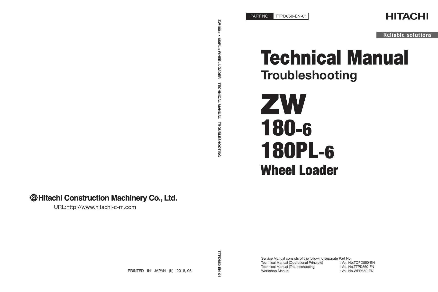
Hitachi ZW180-6 & ZW180PL-6 Wheel Loader Technical Troubleshooting Manual – TTPD850-EN-01
Original price was: $39.95.$24.95Current price is: $24.95.
Complete Hitachi Technical Manual (Troubleshooting) for the ZW180-6 and ZW180PL-6 wheel loaders. 498-page PDF covering operational performance tests, fault-code diagnostics, troubleshooting A and B, monitor service menus, e-Service, component layout, and air conditioner fault diagnosis.
Description
Hitachi ZW180-6 & ZW180PL-6 Wheel Loader Technical Troubleshooting Manual
This is the Hitachi Technical Manual (Troubleshooting) for the ZW180-6 and ZW180PL-6 wheel loaders, published under document number TTPD850-EN-01. It is the diagnostic companion to the Workshop Manual and Engine Manual, and it is written for the experienced technician who needs to measure, compare, and fault-find a wheel loader back to specification. The manual assumes the reader already knows the machine layout and instead concentrates on quantitative testing, electrical signal diagnosis, and structured fault-code / trouble-symptom procedures.
File Details
- Manual type: Technical Manual (Troubleshooting)
- Publication number: TTPD850-EN-01
- Publication date: 2022-05-11
- Brand: Hitachi (Hitachi Construction Machinery Co., Ltd.)
- Models covered: ZW180-6, ZW180PL-6
- Language: English
- Page count: 498
- File format: PDF
Chapters Covered
The manual is arranged into two large sections, each divided into numbered groups.
Section 4 — Operational Performance Test
- Group 1 Introduction — operational performance tests, preparation for performance tests, test area and tool requirements, precautions, and how to make precise measurements
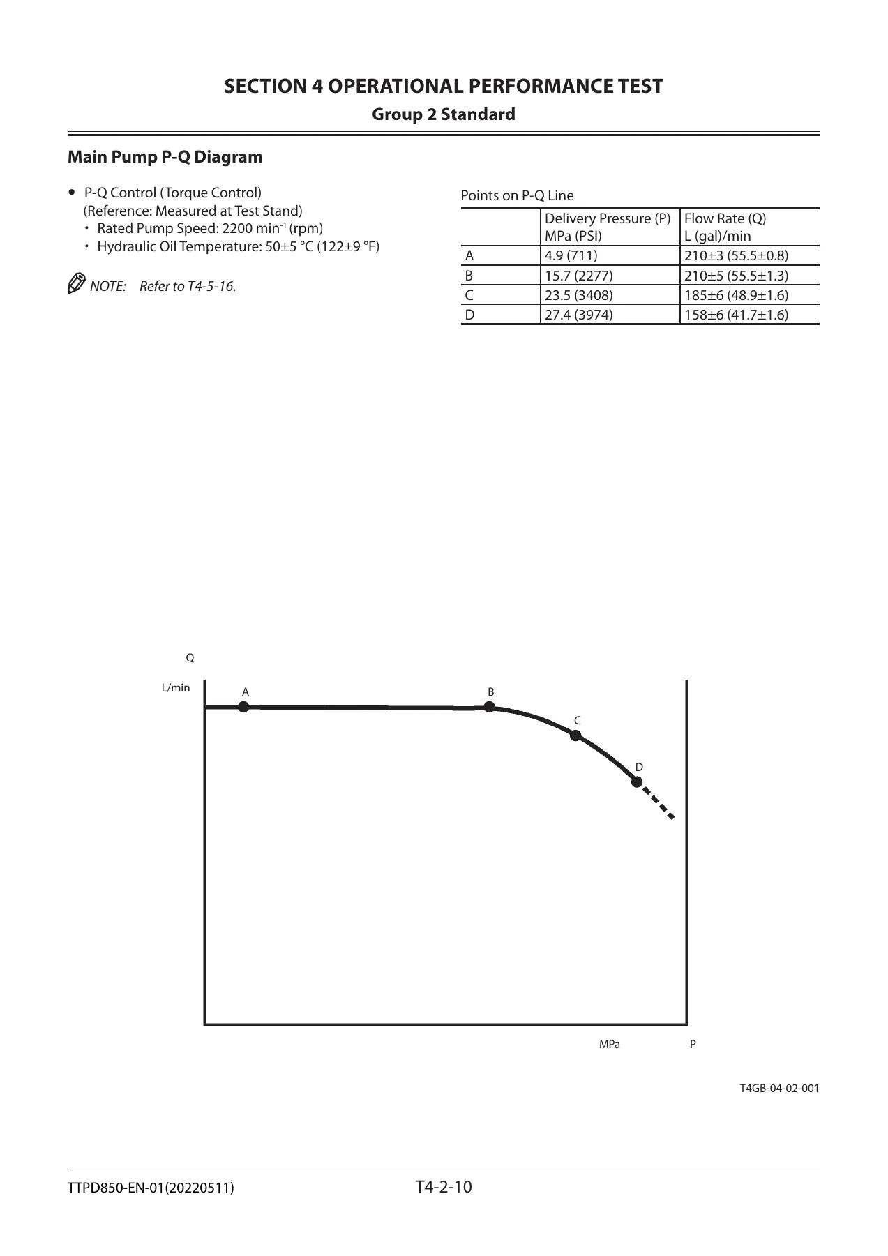
- Group 2 Standard — operational performance standard tables, main pump P-Q diagram, main pump Pi-Q control diagram, sensor activating ranges
- Group 3 Engine Test — engine speed measurement, lubricant consumption
- Group 4 Machine Performance Test — travel speed, service brake function and wear, parking brake function and wear, bucket stopper and bell crank stopper clearance, hydraulic cylinder cycle time, dig function drift, bucket levelness, control lever operating force, control lever stroke
- Group 5 Component Test — primary and secondary pilot pressure, main pump delivery pressure, main relief set pressure, steering relief pressure, overload relief valve set pressure, main pump flow rate measurement, service brake pressure, parking brake release pressure, brake accumulator pressure, brake warning pressures, transmission clutch pressure, torque converter pressure, accumulator gas pressure
- Group 6 Adjustment — aftertreatment device serial number rewrite, DEF tank cleaning, idle speed-up control at final step of engine output restriction (inducement), transmission learning, lift arm angle sensor learning, digging position adjustment
Section 5 — Troubleshooting
- Group 1 Diagnosing Procedure — introduction, diagnosis procedure, electrical system inspection, precautions, connector disconnection instructions, fuse inspection, fusible link inspection, battery voltage check, alternator check, continuity check, voltage and current measurement, check by false signal, test wire harness
- Group 2 Monitor — outline, service menu operating procedures, engine output restriction suspend, monitoring items, controller version, issued warning record, communication terminal status, machine setting, monitor setting, aftertreatment device number, engine tachometer, transmission oil temperature and DEF level gauge, coolant temperature gauge
- Group 3 e-Service — outline, operation data list, snapshot data, communication system
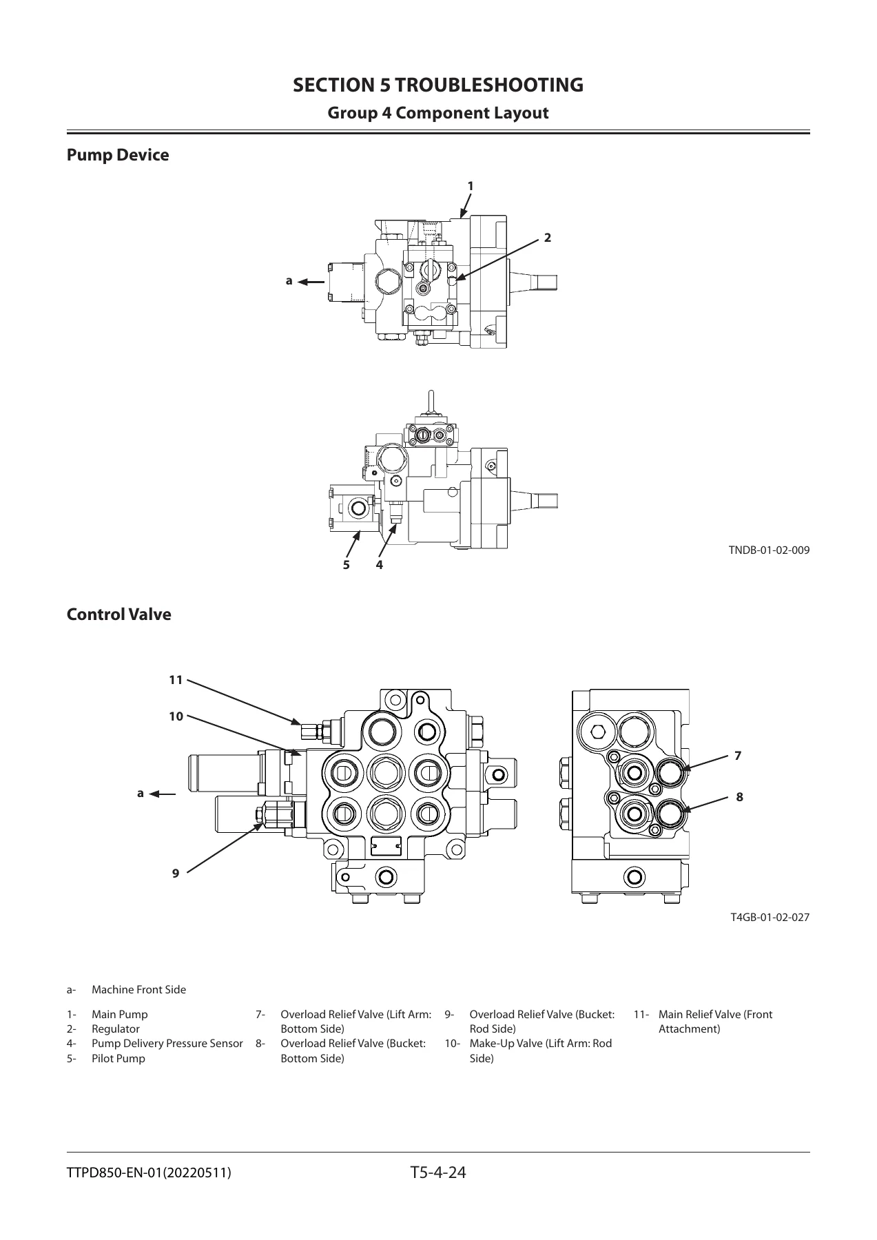
- Group 4 Component Layout — main component overview, electrical system overview, air cleaner and radiator assembly, battery box, hydraulic oil tank, fuel tank, drive unit, front axle, cab, engine, aftertreatment device, fan valve, priority valve, pump device, control valve, manifold valve, parking brake solenoid valve block, brake charge valve, ride control valve, emergency steering block and pump, flow regulator valve, DEF tank and supply module
- Group 5 Troubleshooting A — base machine diagnosis by fault codes; MC, monitor controller, column display controller, air conditioner controller and communication terminal fault code lists; ECM fault code list; TCU fault code list; detailed diagnostic procedures for individual codes from the MC, monitor, and related controllers, including CAN1, CAN2 and CAN3 harness checks
- Group 6 Troubleshooting B — machine diagnosis by trouble symptom; relationship between machine trouble symptoms and related parts; correlation between trouble symptoms and part failures; engine system, all actuator system, front attachment system, steering system, travel system, brake system and other (electrical) system troubleshooting; exchange inspection; air bleeding procedures for brake (axle)
- Group 7 Air Conditioner — outline, functions of main parts, troubleshooting, air conditioner controller fault code list and fault-code procedures, work after replacing components, refilling compressor oil, charging the air conditioner with refrigerant, hose and pipe tightening torque
Read as a whole, this manual gives a technician a complete testing and fault-finding framework for the ZW180-6 and ZW180PL-6. Every measurable function — travel speed, cylinder cycle time, brake pressure, pilot pressure, relief set pressure, pump flow rate, drift, sensor voltage, solenoid valve feedback current, TCU clutch pressure — has a stated measuring method, a stated standard value, and a stated remedy path. Fault-code work is separated into the fault-code procedure (Troubleshooting A) and the symptom-based procedure (Troubleshooting B), so a technician can pick the entry point that matches the actual evidence on the machine.
What This Manual Enables a Technician to Do
With this troubleshooting manual in hand, a technician can carry out the full operational performance test programme for the ZW180-6 and ZW180PL-6 — travel speed at every gear, service and parking brake function and wear measurement, bucket stopper and bell crank clearance, cylinder cycle times, dig function drift, bucket levelness, control lever force and stroke — and compare each reading against Hitachi’s published standard. Component-level testing is covered down to relief valve set pressures, main pump flow rate against the P-Q and Pi-Q curves, service and parking brake pressures, brake accumulator and warning pressures, transmission clutch pressures, torque converter inlet pressure, and accumulator gas pressures.
The electrical side is treated with equal depth. The manual explains how to inspect fuses and fusible links, how to check battery voltage and the alternator, how to check continuity and short circuits in single-line and multi-line harnesses, how to measure voltage and current in the 24 V circuit and the 5 V sensor circuit, how to use a false signal to test a sensor circuit, and how to use the test wire harness. Controller-level fault codes for the MC, monitor controller, column display controller, air conditioner controller, ECM and TCU are listed, and each code is followed by a procedure with an inspection method, an evaluation range and a named cause — so the technician follows a defined route rather than guessing at parts.
The monitor chapter shows the technician how to reach the service menu, work through self-diagnosis, read and clear fault codes, monitor live sensor data, view controller versions, read the issued warning record, read communication terminal status, and carry out the machine settings (transmission learning, lift arm angle sensor learning, digging position adjustment). The e-Service chapter explains operation data, snapshot data and the communication system.
Diagnostics for ECM, TCU, MC, and Air Conditioner
The ECM fault code list pairs each SPN/FMI code with both the MPDr. and Cummins reference numbers, the trouble description, and the effect on machine operation — covering accelerator pedal sensors, fuel delivery pressure, oil pressure, coolant temperature and level, intake manifold pressure and temperature, turbocharger speed, EGR differential pressure and temperature, injector solenoid drivers, VGT actuator, crankshaft and camshaft position, aftertreatment temperature sensors, NOx sensors, DEF tank level, quality and temperature, DEF line heaters, DEF dosing unit, SCR temperature sensors, and DOC temperature sensors.
The TCU fault code list covers shift switch and forward/reverse lever signal errors, transmission oil temperature sensor faults, torque converter input/output and transmission intermediate shaft speed sensors, vehicle speed sensor, each clutch proportional solenoid valve (first, second, third, high-speed forward, low-speed forward, reverse), reverse light relay circuit, TCU power source, sensor power source, proportional solenoid valve power source, internal memory and application errors, and clutch slipping detection. Each TCU code is followed by the behaviour the TCU adopts (for example neutral fix or first/second-speed fix) and the parts to check.
Troubleshooting B groups the symptoms a technician actually meets on the machine — starter does not rotate, engine does not start, engine starts with the forward/reverse lever in gear, power mode not shifted, engine does not stop, auto shut-down not activated, front attachment actuators do not work, actuator speed is slow, actuator does not stop with the lever in neutral, fan speed does not change, fan does not reverse, front attachment power is weak, front attachment drifts, shock at the end of a stroke, bucket auto leveler, lift arm float, lift arm auto leveler height and lower kickout, ride control, bucket tilt and dump speed on the parallel link front attachment, steering power, steering speed, steering shock, emergency steering, travel in forward and reverse, neutral travel, clutch cutoff, travel mode, shift switch, automatic speed shift, downshift switch, hold switch, speed shift retard, parking brake release and apply, service brake braking force, and the individual lighting, horn, wiper, washer, cab light, brake light, work light and reverse buzzer circuits. Each symptom has its own procedure with conditions, evaluation and named causes.
The air conditioner section covers the layout and main parts — controller, power transistor, blower motor relay, compressor relay, frost sensor, high/low pressure switch, re-circulated air temperature sensor, ambient temperature sensor, solar radiation sensor, and the fresh/re-circulated air, air mix and air vent damper servo motors — and then gives the air conditioner controller fault code list with procedures for codes 11 to 92, plus systematic fault trees for faulty cooling, faulty heating, blower motor failure, compressor clutch failure, cooling circuit checks by manifold gauge, and refrigerant charging procedure with the required R134a quantities, compressor oil replenishment quantities, and hose and pipe tightening torques.
Why Correct Procedures and Specified Values Matter on the ZW180-6 and ZW180PL-6
A wheel loader of this size depends on its hydraulic, transmission, brake and steering systems working within narrow tolerances. A relief valve set a few percent out, a clutch pressure drifting below specification, a pressure sensor reading high or low, or a brake accumulator losing charge can each produce symptoms that look like something else entirely. The structured test programme, the P-Q and Pi-Q pump curves, the sensor activating ranges, the fault-code tables and the symptom-based procedures in this troubleshooting manual are what allow a technician to separate a genuine component failure from a harness fault, a dirty connector, a clogged port, a poorly adjusted valve, or a sensor that has simply drifted. It also enables correct completion of the calibration routines — transmission learning, lift arm angle sensor learning, digging position adjustment — that keep the electronic controls aligned with the machine after repairs.
IMAGES PREVIEW
Instant PDF Delivery
The Hitachi ZW180-6 & ZW180PL-6 Wheel Loader Technical Troubleshooting Manual is delivered as a downloadable PDF immediately after payment. No shipping, no waiting on a physical book, and no restrictions on where you read it — open it on a laptop or tablet in the workshop, on a phone at the machine, or print the pages you need for the job in front of you. Sections can be printed separately for the fault-code tables, the performance standards, or the torque and pressure pages you use most.

Reviews
There are no reviews yet.