
Hitachi ZW310 Wheel Loader Technical Manual – Operational Principle, Troubleshooting and Workshop Manual
Original price was: $44.95.$26.95Current price is: $26.95.
The complete Hitachi ZW310 Wheel Loader Technical Manual in one PDF, combining the Operational Principle, Troubleshooting and Workshop Manual volumes for the ZW310 (EU) and ZW310 (Standard/General) with the OM460LA engine – hydraulics, transmission, axles, electrical system, fault codes, performance tests and full disassembly procedures.
Description
Hitachi ZW310 Wheel Loader Technical Manual – Operational Principle, Troubleshooting and Workshop Manual
This Hitachi ZW310 Wheel Loader Technical Manual brings together the three volumes Hitachi issues for the ZW310: the Technical Manual (Operational Principle), the Technical Manual (Troubleshooting) and the Workshop Manual. It is written for the experienced technician and covers the machine from the theory of how each system functions, through the performance tests and fault-code diagnostics used to prove it, right down to the removal, disassembly, assembly and installation procedures for the major components.
Everything is documented for the ZW310 wheel loader in both its EU and Standard/General configurations, with the OM460LA diesel engine, the TCM TM310 transmission, the load-sensing hydraulic system and the electronic control network that ties the machine together. The ZW310 Technical Manual is the reference a workshop reaches for when a machine has to be brought back to specification rather than simply kept running.
File Details
- Manual type: Technical Manual (Operational Principle and Troubleshooting) combined with the Workshop Manual
- Brand: Hitachi Construction Machinery
- Model: ZW310 Wheel Loader
- Configuration covered: ZW310 (EU) and ZW310 (Standard/General)
- Language: English
- File format: PDF
- Page count: Approximately 1,532 pages
- Document reference: 4HA series (T4HA, 4HAT and 4HAW page numbering)
Chapters Covered
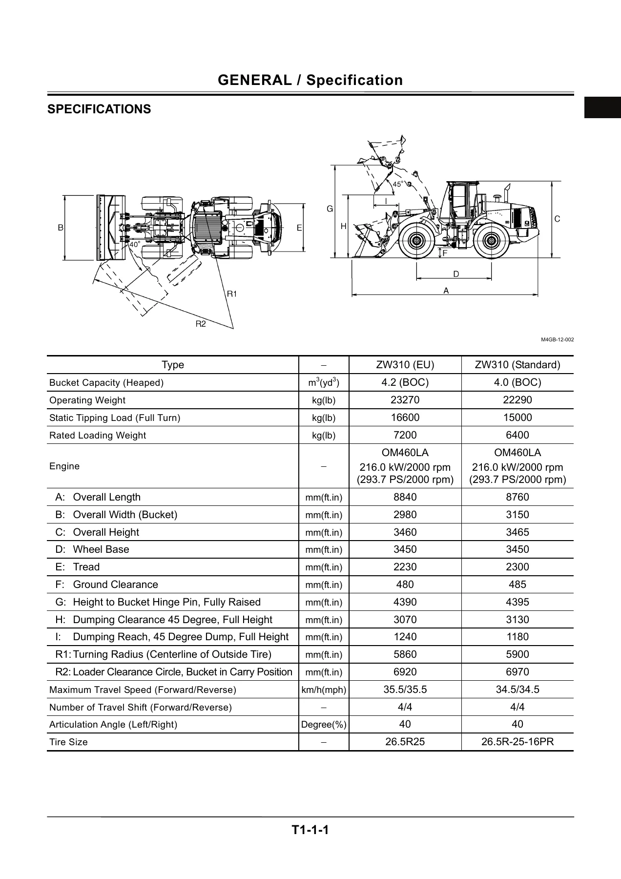
- Section 1 – General: Specifications; Component Layout (main, electrical overview, cab, controller and relays, right console, monitor and switches, monitor panel, engine and fan pump, pump device and drive unit, control valve, ride control valve, charging block and fan motor, steering valve and emergency steering pump); Component Specifications (engine, engine accessories, hydraulic component, electrical component)
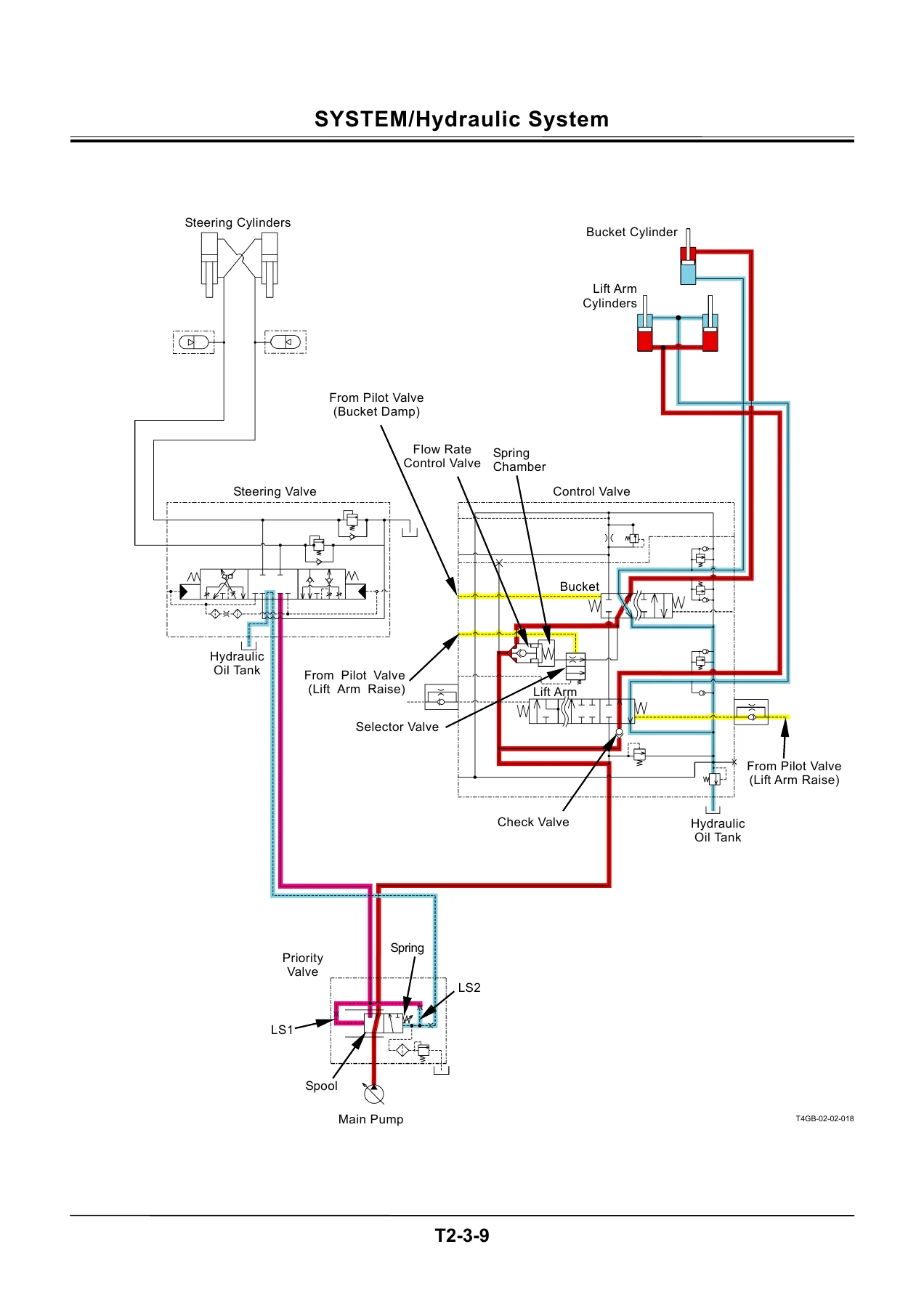
- Section 2 – System: Control System (engine control, pump control, transmission control, other controls, control by electric and hydraulic combined circuit); ECM System (outline, fuel injection control); Hydraulic System (main circuit, pilot circuit, steering circuit, hydraulic drive fan circuit); Electrical System (main circuit, electric power, indicator light check, accessory, preheat, starting, charging, surge voltage prevention, engine stop, head light, turn signal, brake light, hazard light, horn, reverse light and buzzer, parking brake, emergency steering check)
- Section 3 – Component Operation: Pump Device (main pump, regulator, priority valve, pilot pump, pump delivery pressure switch, steering main relief valve); Control Valve; Hydraulic Fan Motor; Steering Pilot Valve; Steering Valve; Pilot Valve; Charging Block; Ride Control Valve; Drive Unit (torque converter, transmission, transmission regulator valve, transmission control valve, manual spool, proportional solenoid valve); Axle (differential, torque proportioning differential, limited slip differential, service brake, final drive and axle shaft); Brake Valve; Others (pilot shut-off valve, propeller shaft, emergency steering check block, emergency steering pump)
- Section 4 – Operational Performance Test: Introduction; Standard (ZW310 EU and ZW310 General performance standard tables, main pump P-Q curves, sensor activating ranges); Engine Test; Wheel Loader Test; Component Test; Adjustment (transmission learning, lift arm angle sensor learning, unit injector setting)
- Section 5 – Troubleshooting: Diagnosing Procedure and monitor service mode; Dr. ZX; e-Wheel; Component Layout; Troubleshooting A (MC, ECM1 and ECM2, ICF, satellite terminal and monitor unit fault code lists and flow charts, CAN harness checks, connector terminal roles); Troubleshooting B (engine, front attachment, travel, brake, steering and other system troubleshooting); Troubleshooting C (monitor, gauges, indicators and lamps); Electrical System Inspection
- Workshop Manual – Section 1 General: Precautions for disassembling and assembling; Tightening torque specifications, torque chart and piping joints; Periodic replacement parts; Painting; Bleeding air from the hydraulic oil tank
- Workshop Manual – Section 2 Body (Uppermost): Cab; Counterweight; Center hinge; Hood; Hydraulic oil tank; Pump device; Control valve; Pilot valve; Pilot shut-off valve; Hydraulic fan pump and motor
- Workshop Manual – Section 3 Body (Travel System): Tire; Drive unit; Axle; Propeller shaft; Brake valve; Charging block; Steering pilot valve; Steering valve; Steering cylinder
- Workshop Manual – Section 4 Front Attachment: Front attachment; Cylinder (lift cylinder and bucket cylinder)
Read together, the three volumes give a technician the full picture of the ZW310 rather than a single slice of it. The Operational Principle section explains what each hydraulic, electrical and electronic subsystem is supposed to do and how its components interact, so a symptom can be traced back to a circuit instead of guessed at. The Troubleshooting section supplies the performance standards the machine should meet, the step-by-step measuring procedures to confirm them, and the fault-code and symptom-based flow charts that narrow the cause down to a specific sensor, solenoid, harness or controller. The Workshop Manual then takes over with the disassembly and assembly procedures, tightening torques, maintenance standards and special tool references needed to actually carry out the repair.
Systems and Components Documented
The ZW310 Wheel Loader Technical Manual reaches into every major assembly on the machine. On the hydraulic side that includes the bent-axis variable displacement main pump and its regulator, the priority valve, the two-spool control valve with its main relief, overload relief, load check, restriction and flow control valves, the pilot valve and pilot shut-off valve, the charging block with its priority valve, service brake accumulators and pilot accumulator, the steering pilot valve and steering valve, the ride control valve and the hydraulic fan motor with its flow control and reverse control valves.
On the driveline side the manual documents the torque converter, the TM310 transmission with its forward, reverse, 1st and 2nd speed and 3rd and 4th speed clutch shafts, the transmission regulator valve and control valve with its proportional solenoids and manual emergency travel spool, plus the propeller shafts, the axles with their differentials, final drives, axle shafts and wet multi-disc service brakes, and the brake valve.
The electrical and electronic coverage is equally complete: the MC main controller, ECM1 and ECM2 engine control modules, the ICF information controller and the monitor unit, the CAN network between them, and the sensors, switches and proportional solenoid valves each controller reads and drives.
Troubleshooting and Diagnostics
Fault-code work is supported for every controller. The MC, ECM1 and ECM2, ICF, satellite terminal and monitor unit fault code lists are reproduced with the trouble, the likely cause, the affected control and the symptoms the operator would notice. Each code that needs it is backed by a flow chart that walks through the connector, terminal, continuity and voltage checks, including the CAN harness continuity and short-circuit checks and the terminal roles for the ECM1 and ECM2 connectors.
Where no fault code appears, Troubleshooting B starts from the symptom instead – engine, front attachment, travel, brake or steering – and tables the relationship between the complaint and the parts that can cause it before the flow charts begin. Monitor, gauge and indicator problems are handled separately in Troubleshooting C, and the Electrical System Inspection group covers fuse and fusible link checking, battery and alternator checks, continuity and short-circuit testing, voltage and current measurement, 5 V circuit checks and the false-signal method.
Performance Testing and Adjustment
The Operational Performance Test section gives the ZW310 EU and ZW310 General standard tables in full – engine speeds, travel speeds, service and parking brake capacity and wear limits, cylinder cycle times, drift checks, lever operating forces and strokes, primary and secondary pilot pressures, main relief and overload relief pressures, service brake, parking brake and accumulator pressures, brake warning pressures, transmission clutch pressure and torque converter inlet and outlet pressures. Engine tests, wheel loader tests and component tests are laid out with the switch positions, oil temperatures and measuring points each one requires. The adjustment group covers transmission learning, lift arm angle sensor learning and unit injector setting.
Workshop Procedures
The Workshop Manual is where the ZW310 service manual becomes hands-on. Every removal and installation procedure lists the wrench sizes and tightening torques alongside the steps, and the disassembly and assembly sections are illustrated with exploded views and cross-sectional drawings. Maintenance standards are given for the parts that wear – plunger shoe thickness, rotor clearance, servo piston clearance, spool-to-body clearances, seal ring clearances and more – so wear can be measured against a limit rather than estimated. Periodic replacement parts, piping joint torque tables, seal and O-ring handling, floating seal precautions and nylon sling inspection are all covered in the General group.
Who This Manual Is For
This Hitachi ZW310 technical manual PDF suits the workshop technician, the field service engineer, the fleet maintenance planner and the technically minded owner who needs the manufacturer’s own procedures rather than a generic repair guide. It supports routine service and adjustment through to major component overhaul, fault finding on the electronic control network, hydraulic pressure and flow testing, brake and accumulator servicing, transmission clutch work and axle repair.
Get the Complete ZW310 Documentation
Having the operational principle, the troubleshooting procedures and the workshop procedures in one document means a fault can be followed from theory to diagnosis to repair without switching between separate books. Correct specifications and correct tightening torques are what keep a wheel loader reliable, and this manual supplies them for the ZW310 directly.
IMAGES PREVIEW
The Hitachi ZW310 Wheel Loader Technical Manual is delivered as an instant PDF download – no shipping, no waiting for a courier. It opens on any laptop, tablet or phone, can be printed for the workshop bench, and the page-numbered sections make it easy to jump straight to the group you need.
Reviews
There are no reviews yet.