
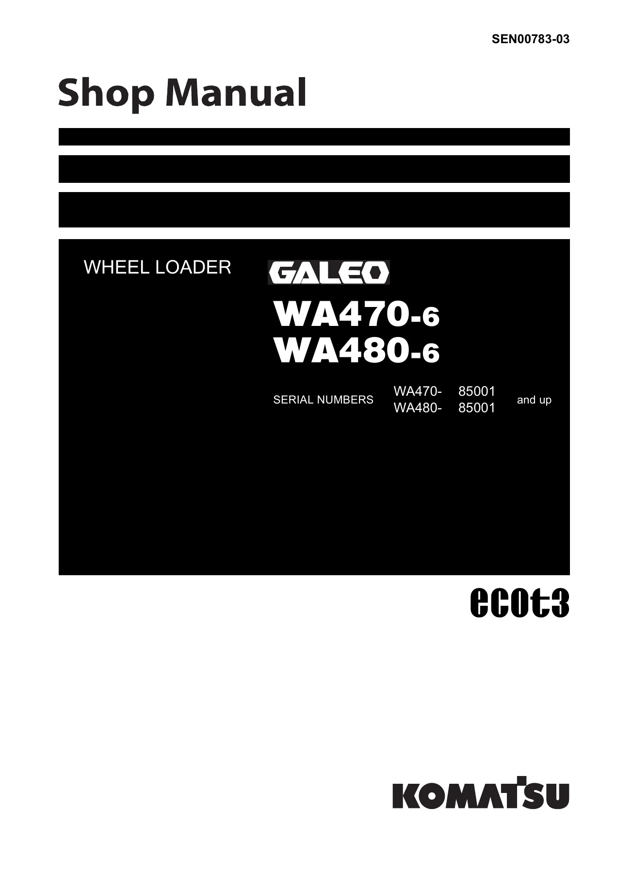
Komatsu WA470-6 WA480-6 Wheel Loader Shop Manual SEN00783-03 PDF
Original price was: $49.95.$29.95Current price is: $29.95.
Workshop service manual for Komatsu WA470-6 and WA480-6 wheel loaders, serial numbers 85001 and up. Covers machine specifications, system structure and function, standard service values, testing and adjustment, fault diagnosis, component removal and installation, disassembly and assembly, and hydraulic/electrical diagrams.
Description
The Komatsu WA470-6 WA480-6 Wheel Loader Shop Manual SEN00783-03 PDF is a detailed workshop reference for WA470-6 and WA480-6 wheel loaders with serial numbers 85001 and up. It brings together specification data, component construction and operating principles, maintenance standards, testing and adjusting procedures, troubleshooting information, disassembly and assembly instructions, and hydraulic and electrical drawings. Its coverage follows the machine from basic dimensions and service data through power train, steering, brakes, hydraulics, work equipment, cab systems, electronic controls, fault codes, major component removal and installation, and circuit diagrams.
File Details
- Manual type: Shop Manual
- Brand: Komatsu
- Models: WA470-6, WA480-6
- Serial coverage: WA470-6 85001 and up; WA480-6 85001 and up
- Document number: SEN00783-03
- Language: English
- Page count: 1559 pages
- File format: PDF
Workshop Information for WA470-6 and WA480-6
This manual is organized around the information needed for workshop service. The introductory material explains safety precautions, the meaning of maintenance-standard terms, correct handling of electrical and hydraulic components, wire-code identification, general removal and installation precautions, push-pull couplers, tightening torques, and unit conversions. The specification section then establishes machine data before the manual moves into the construction, function, and service criteria of individual systems.
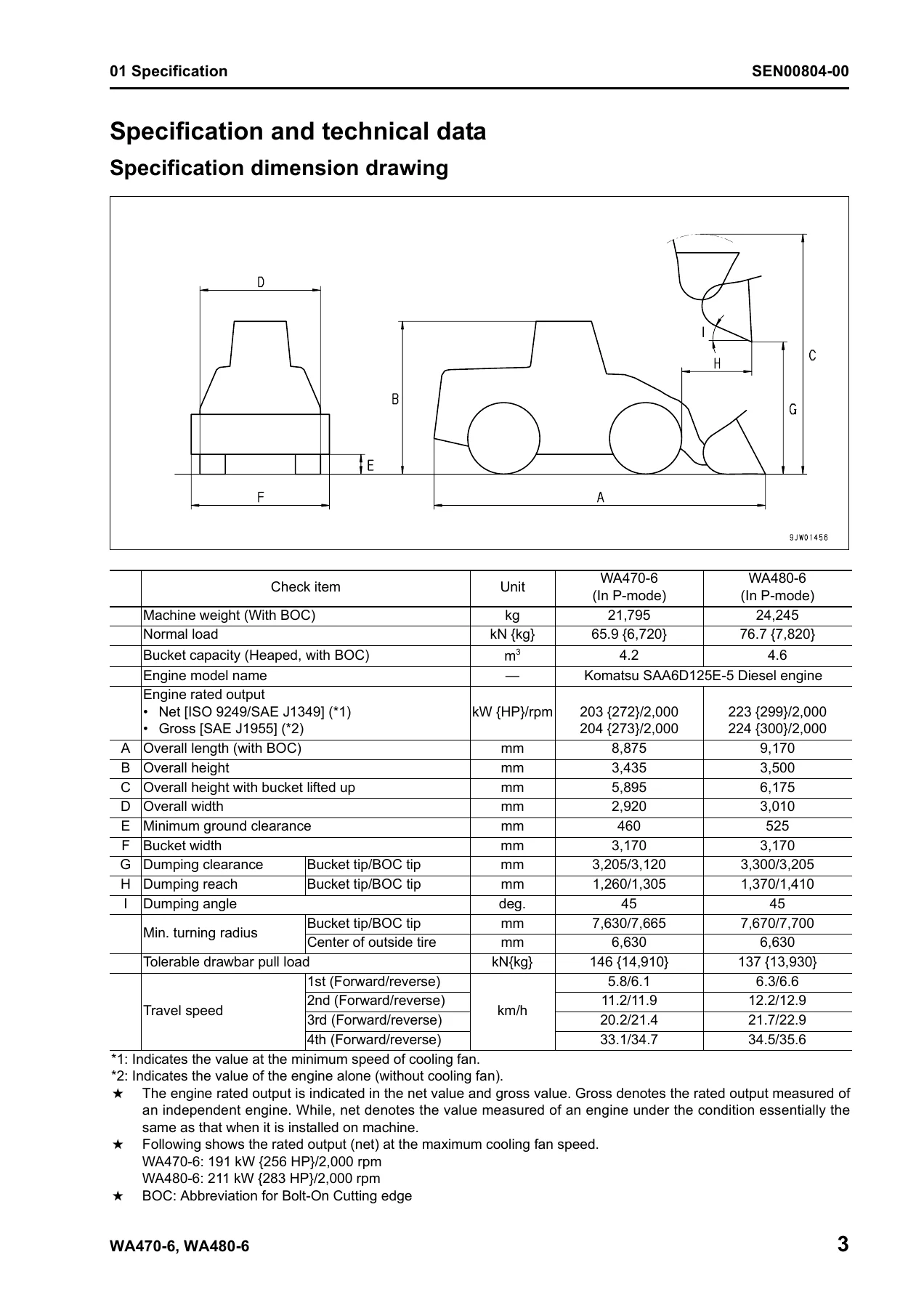
For the two covered loaders, the specification pages identify the Komatsu SAA6D125E-5 diesel engine. It is described as a 4-cycle, water-cooled, in-line 6-cylinder direct-injection engine with turbocharger and air-cooled aftercooler, with a 125 x 150 mm bore and stroke and 11.04 l {11,040 cc} displacement. In P-mode, the manual lists net rated output of 203 kW {272 HP}/2,000 rpm for the WA470-6 and 223 kW {299 HP}/2,000 rpm for the WA480-6. The same specification material gives machine weights of 21,795 kg and 24,245 kg respectively, heaped bucket capacities of 4.2 m3 and 4.6 m3, travel speeds, dimensions, turning data, tire sizes, brake construction, steering type, and power-train details.
Fluid and system information is also built into the service data. The manual lists a 47 l specified engine-oil-pan capacity for both models, a 65 l transmission-case specified capacity, a 413 l fuel-tank capacity, and a 61 l coolant-system capacity. Hydraulic-system specified capacity is shown as 270 l for the WA470-6 and 275 l for the WA480-6, while refill capacity is listed as 173 l for both. Pump types and deliveries, steering and work-equipment cylinder dimensions, control-valve pressures, component weights, and maintenance-standard measurements give the technician reference values to compare with actual machine condition.
System Construction, Function, and Service Standards
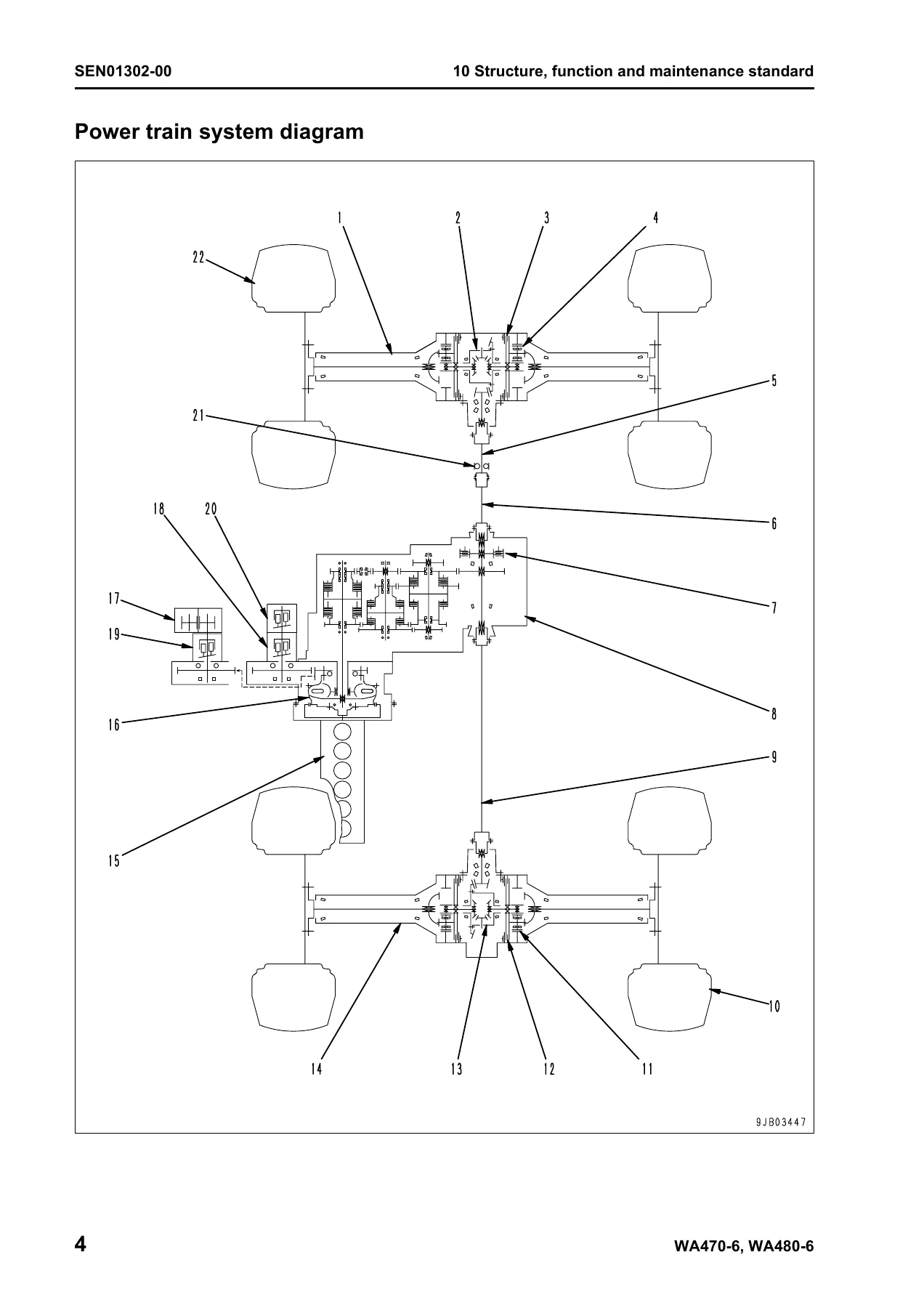
The structure and function material goes well beyond identification diagrams. Power flow through the torque converter, transmission, drive shafts, differentials, and final drives is illustrated and explained, including standard and lockup torque-converter arrangements and the four forward/four reverse transmission. Hydraulic chapters describe the power-train, steering, work-equipment, cooling-fan, and emergency-steering pumps, together with control valves, CLSS, PPC circuits, accumulators, cylinders, and work-equipment functions. Steering, brake, axle, bucket, cab, air-conditioning, machine-monitor, transmission-controller, starting, stopping, preheating, power-mode, parking-brake, and sensor circuits are treated as individual service subjects.
Maintenance-standard pages provide dimensional criteria, clearances, wear limits, spring loads, backlash values, pressures, and other judgement points for components covered by the manual. This is useful when inspection has progressed beyond a visual check and a part must be measured against a stated standard or repair limit. The manual also includes general tightening-torque tables and specific tightening values throughout component illustrations and repair procedures.
Chapters Covered
- 00 – Index and foreword
- Safety notice
- How to read the shop manual
- Explanation of terms for maintenance standard
- Handling electric equipment and hydraulic components
- How to read electric wire code
- Precautions when carrying out operations
- Push-pull type coupler disconnection and connection
- Standard tightening torque table
- Conversion table
- 01 – Specification
- Specification dimension drawing
- Machine specifications and technical data
- Component weight table
- Fuel, coolant and lubricant information and capacities
- 10 – Structure, function and maintenance standard
- Engine and cooling system
- Power train, torque converter, transmission, axles, differentials and final drives
- Steering system and emergency steering
- Brake system and parking brake
- Undercarriage, frame and center hinge
- Hydraulic system Part 1: piping, tanks, pumps, control valve and CLSS
- Hydraulic system Part 2: PPC valve and accumulators
- Work equipment, bucket, linkage, positioner, boom kick-out and cylinders
- Cab and air conditioner
- Electrical system Part 1: machine monitor system
- Electrical system Part 2: transmission controller system
- Electrical system Part 3: transmission control, KOMTRAX, engine circuits, switches and sensors
- 20 – Standard value table
- Standard service values for engine and chassis
- 30 – Testing and adjusting
- Testing and adjusting Part 1: engine, fuel, power train and steering checks
- Testing and adjusting Part 2: fan, brake, work-equipment, electrical and monitor checks
- Testing and adjusting Part 3: machine-monitor special functions and inspection information
- 40 – Troubleshooting
- Failure-code table and fuse locations
- General troubleshooting procedure and connector information
- Failure-code troubleshooting, Parts 1 through 10
- Electrical-system troubleshooting (E-mode)
- Hydraulic and mechanical troubleshooting (H-mode)
- Engine troubleshooting (S-mode)
- 50 – Disassembly and assembly
- General repair information, coating materials and special tools
- Engine and cooling-system removal and installation
- Power train Part 1: torque converter, transmission, clutch packs and parking brake
- Power train Part 2: front/rear axles and differential
- Undercarriage and frame: center hinge pin and counterweight
- Hydraulic system: valves, tank and pump assemblies
- Work-equipment assembly
- Cab, floor frame, glass and operator seat
- Electrical assemblies including air conditioner and controllers
- 90 – Diagrams and drawings
- Power-train and main hydraulic circuit diagrams
- Electrical circuit and connector arrangement diagrams
Taken together, these chapters give a technician a path from understanding how a system is built, to checking its standard values, measuring operating condition, tracing a fault, and then removing or repairing the affected assembly. The disassembly material includes procedures for major jobs such as engine removal and installation, radiator and aftercooler work, fuel supply pump and injector removal, cylinder-head work, torque-converter and transmission removal, transmission and clutch-pack disassembly, axle and differential work, hydraulic valve and pump removal, cab removal, and controller replacement. The manual notes that shop manuals are divided into chassis and engine volumes and directs engine-unit work to the applicable engine volume where required.
Testing and Troubleshooting Depth
The Komatsu WA470-6 WA480-6 Wheel Loader Shop Manual SEN00783-03 PDF includes practical measurement and diagnosis procedures rather than only component descriptions. Engine-related checks include engine speed, exhaust-gas color and temperature, valve clearance, compression pressure, blow-by pressure, engine-oil pressure, EGR checks, boost pressure, fuel pressure, fuel return and leakage, fuel-circuit bleeding, and fuel-system leak testing. Power-train procedures include oil-pressure measurements, transmission-speed-sensor adjustment, torque-converter and transmission circuit flushing, and methods for moving the machine when a transmission valve is faulty. Steering, brake, hydraulic-fan, work-equipment, bucket-positioner, boom kick-out, electrical, KOMTRAX, sensor, controller, and machine-monitor checks are also covered.
Fault diagnosis is divided into failure-code troubleshooting plus electrical, hydraulic/mechanical, and engine symptom modes. The failure-code sections address transmission clutch and ECMV signals, controller communication, sensors, solenoids, switches, engine-management faults, pressure and temperature conditions, steering-related circuits, work-equipment controls, and monitor/controller faults. E-mode follows electrical symptoms such as starting, lighting, wiper, horn, buzzer, air-conditioning, and KOMTRAX problems. H-mode works through travel, torque-converter, steering, brake, lift-arm, bucket, work-equipment, and ECSS symptoms. S-mode covers engine starting, power, running quality, smoke, oil consumption, fuel consumption, oil pressure, overheating, abnormal noise, and vibration.
Repair Procedures and Diagrams
Once diagnosis points to a component, the disassembly and assembly section provides the next level of information. Procedures include safety steps, component weights where specified, lifting instructions, hose and connector identification, oil draining and refilling, removal sequences, installation steps, tightening values, and post-repair checks. Hydraulic repair coverage includes the steering demand valve, work-equipment valve, brake charge valve, hydraulic tank, steering and power-train pump assembly, and work-equipment/cooling-fan pump assembly. Power-train coverage includes both standard and lockup torque-converter configurations, transmission internals, clutch packs, parking brake, axle housings, and differentials.
The drawing section supplies power-train hydraulic, main hydraulic, electrical, and connector-arrangement diagrams. Earlier chapters also contain detailed sectional drawings and system schematics for pumps, valves, transmission assemblies, axles, differentials, final drives, steering and braking components, work equipment, and electrical controls. These illustrations help connect the written procedure to actual component layout and oil or electrical flow.
Service the WA470-6 and WA480-6 with the Correct Workshop References
For owners, workshop technicians, and repair teams working on WA470-6 or WA480-6 wheel loaders from serial number 85001 and up, this manual supports inspection, measurement, adjustment, fault tracing, component removal, installation, disassembly, assembly, and circuit diagnosis across the machine systems covered. Having the stated procedures, standard values, service limits, pressures, torque references, wiring information, and hydraulic diagrams available at the job helps repairs follow the specifications intended for these models instead of relying on memory or generic data.
IMAGES PREVIEW
The Komatsu WA470-6 WA480-6 Wheel Loader Shop Manual SEN00783-03 PDF is supplied as an instant PDF download after purchase. There is no physical book to ship or wait for: open the manual on a computer, tablet, or phone, keep it available in the workshop, and print the pages needed for a particular repair or diagnostic job.
Reviews
There are no reviews yet.