
Hitachi ZX200-5G ZX210-5G Excavator Technical Manual – Operational Principle PDF
Original price was: $34.95.$19.95Current price is: $19.95.
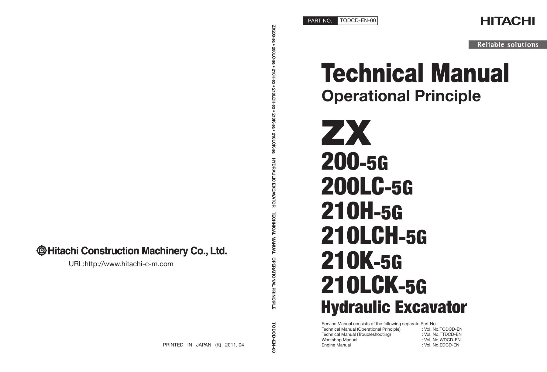
Hitachi Technical Manual (Operational Principle) TODCD-EN-00 for ZX200-5G, ZX200LC-5G, ZX210H-5G, ZX210LCH-5G, ZX210K-5G and ZX210LCK-5G hydraulic excavators. Covers controllers, control system, hydraulic system, electrical system, pump device, swing device, control valve, pilot valve, travel device, signal control valve, operational performance testing and troubleshooting. 354-page instant PDF download.
Description
Hitachi ZX200-5G and ZX210-5G Series Technical Manual – Operational Principle
This is the Technical Manual (Operational Principle) for the Hitachi ZX200-5G and ZX210-5G series hydraulic excavators, published under part number TODCD-EN-00. It explains how each device, controller and hydraulic circuit in these machines actually works – the operating principles, signal flows, control logic and adjustment values that a technician needs before attempting diagnosis, repair or calibration. Where a workshop manual tells you which bolt to remove, this operational principle manual tells you why the system behaves the way it does.
The document applies to the ZX200-5G, ZX200LC-5G, ZX210H-5G, ZX210LCH-5G, ZX210K-5G and ZX210LCK-5G models, all powered by the ISUZU CC-6BG1T engine rated at 125 kW / 2100 min-1 (170 PS / 2100 rpm). It is the operational principle volume of the three-part Hitachi service literature set – the other volumes being the Troubleshooting manual (TTDCD-EN) and the Workshop Manual (WDCD-EN).
File Details
- Manual type: Technical Manual (Operational Principle) – TO
- Brand: Hitachi Construction Machinery Co., Ltd.
- Models covered: ZX200-5G, ZX200LC-5G, ZX210H-5G, ZX210LCH-5G, ZX210K-5G, ZX210LCK-5G
- Engine: ISUZU CC-6BG1T (125 kW / 2100 min-1, 170 PS / 2100 rpm)
- Language: English
- Part number: TODCD-EN-00
- Date: Printed in Japan (K) 2011, 04
- Page count: 354 pages
- File format: PDF (instant download)
Chapters Covered
The manual is organised into five sections with numbered groups, using the T1-1-1 style page reference system (Technical Manual / Section / Group / Page).
- Section 1 – General
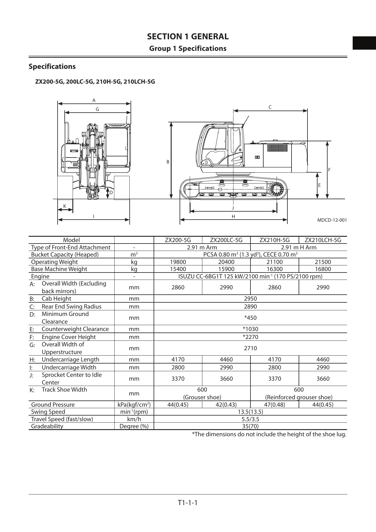
- Group 1: Specifications (dimensions, operating weight, bucket capacity, ground pressure, travel speed, gradeability, working ranges for grouser shoe)
- Group 2: Component Layout (main component, electrical system overview, engine, in-cab electrical, rear tray electrical, switch panel, relays, pump device, control valve, signal control valve, swing device, travel device, 3-spool solenoid valve unit, attachment spec parts layout)
- Group 3: Component Specifications (engine, engine accessories, hydraulic component, electrical component)
- Section 2 – System
- Group 1: Controller
- Group 2: Control System – engine control (dial, ECO, power mode, ECO mode, travel HP mode, auto-idle, hydraulic oil temperature auto-warming up, idle speed-up, engine starting idle speed-up, attachment operation speed limit), pump control (speed sensing, hydraulic oil temperature pump torque decrease, travel torque-up, attachment pump torque decrease, pump 1 & 2 flow rate limit), valve control (power digging, auto-power lift, travel motor displacement angle, arm regenerative, digging regenerative, breaker 1/2, pulverizer, crusher), other control (work mode, breaker alarm, swing alarm, travel alarm)
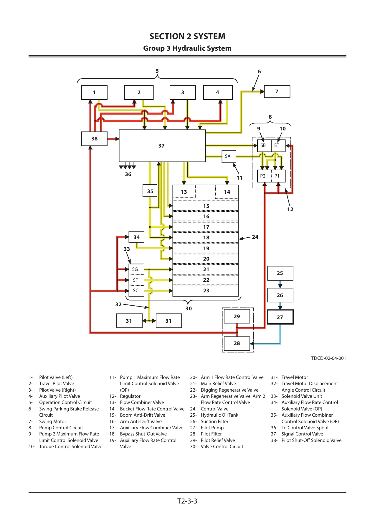
- Group 3: Hydraulic System – pilot circuit (operation control, pump control, valve control, travel motor displacement angle control, swing parking brake release), main circuit
- Group 4: Electrical System – electric power circuit, CAN circuit, ACC circuit, preheating circuit, starter circuit, charging circuit, surge voltage prevention, pilot shut-off circuit, engine stop circuit, monitor circuit, security circuit, radio circuit, air conditioner circuit, work light circuit, wiper/washer circuit, cab light circuit
- Section 3 – Component Operation
- Group 1: Pump Device – main pump, regulator, solenoid valve, pilot pump, pump delivery pressure sensor, pump control pressure sensor, N sensor
- Group 2: Swing Device – swing reduction gear, swing motor, swing parking brake, valve unit
- Group 3: Control Valve – hydraulic circuit, flow combiner valve, main relief valve, overload relief valve, regenerative valve, anti-drift valve, flow rate control valve, digging regenerative valve, boom lower meter-in cut valve, auxiliary flow combiner valve and bypass shut-out valve
- Group 4: Pilot Valve – front attachment / swing and travel pilot valve operation, auxiliary pilot valve operation, shockless function
- Group 5: Travel Device – travel reduction gear, travel motor, parking brake, travel brake valve, overload relief valve, travel mode control
- Group 6: Signal Control Valve – pilot port, shuttle valve, shockless valve, pump 1 & 2 flow rate control valve, bucket flow rate control valve control spool, flow combiner valve control spool, swing parking brake release spool, arm 1 flow rate control valve control spool
- Group 7: Others (Upperstructure) – pilot shut-off solenoid valve, solenoid valve, pilot relief valve, EC motor, hose rupture valve
- Group 8: Others (Undercarriage) – swing bearing, center joint, track adjuster (front idler integrated type)
- Section 4 – Operational Performance Test
- Group 1: Introduction
- Group 2: Standard
- Group 3: Engine Test
- Group 4: Excavator Test
- Group 5: Component Test
- Group 6: Adjustment
- Section 5 – Troubleshooting
- Group 1: Diagnosing Procedure
- Group 2: Monitor
- Group 3: e-Service
- Group 4: Component Layout
- Group 5: Troubleshooting A
- Group 6: Troubleshooting B
- Group 7: Air Conditioner
What this adds up to is a complete explanation of the machine as a controlled system rather than a collection of parts. The controller group alone describes how the Main Controller (MC), Engine Controller (ECF), Monitor Controller, Wiper/Light Controller, Air Conditioner Controller, Radio Controller and Communication Controller talk to each other over the CAN bus, and what each one is responsible for. The control system group then walks through every automatic function the operator feels but never sees – ECO mode reducing engine speed by 100 min-1 when the levers sit in neutral, travel HP mode lifting the engine back up when the travel pressure sensor and pump pressures meet their thresholds, auto-idle cutting in roughly 3.5 seconds after the levers are released, and hydraulic oil temperature auto-warming up holding a raised idle for up to 12 minutes at 0 degrees C or below. Each function is given its purpose, its activation conditions and a graph showing the engine speed versus dial position relationship.
The hydraulic system section is the core of the book. It traces the pilot circuit from the pilot pump through the pilot valves, the signal control valve, the pump regulators and the valve control spools, then does the same for the main circuit from pump 1 and pump 2 through the 4-spool and 5-spool control valve sections to the cylinders, travel motors and swing motor. Combined operation examples are diagrammed in detail – boom raise while swinging, arm roll-in while travelling, boom lower while another actuator is working, attachment operation with the bypass shut-out valve – so the reader can see exactly which pump feeds which actuator and when the flow combiner valve merges the two pump outputs.
What This Manual Lets You Do
This is the volume to reach for when a machine behaves incorrectly but the fault codes don’t explain why. Because it documents the intended behaviour of every control function – the exact reference pressures that trigger power digging, auto-power lift, digging regenerative control, arm regenerative control and travel motor displacement angle control – it gives a technician a baseline to test against. When the arm hesitates, when the boom drifts, when travel mistracks on a slope, or when an attachment runs slower than it should, the operational principle behind the affected circuit is what separates a parts-swapping guess from a correct diagnosis.
The manual also supports the full line of optional attachment work. Separate control sections cover breaker 1 and breaker 2, pulverizer, crusher, grapple and clamshell configurations, including the selector valve, accumulator, secondary pilot relief pressure control and maximum pump 2 flow rate limit controls that these options add. Technicians working on machines fitted with auxiliary hydraulics will find the layout of the attachment spec parts and the associated solenoid valves documented in Section 1 and explained function by function in Section 2.
Correct operational principles matter because these excavators are computer-controlled. The MC, ECF and monitor are constantly adjusting engine speed, pump displacement and valve position in response to sensor input, and a repair carried out without understanding the control logic can easily leave a machine running in a safe mode or with a control function permanently disabled. The adjustment values and sensor reference pressures in this manual – from the auto-idle speed adjustment through the Li speed and warming up speed settings – are the ones the manufacturer uses to set the machine up after service.
IMAGES PREVIEW
Instant PDF Delivery
The manual is supplied as a PDF download, available immediately after checkout. There is no physical shipment, no waiting and no shipping cost. The file opens on any computer, tablet or smartphone and can be printed page by page for use in the workshop, so a technician can work from a clean copy of the relevant circuit diagram while keeping the original file intact. Whether you are diagnosing a control valve fault, setting up an attachment, or simply want to understand how the ZX200-5G and ZX210-5G series machines are meant to behave, this operational principle volume is the reference that answers the question.

Reviews
There are no reviews yet.