
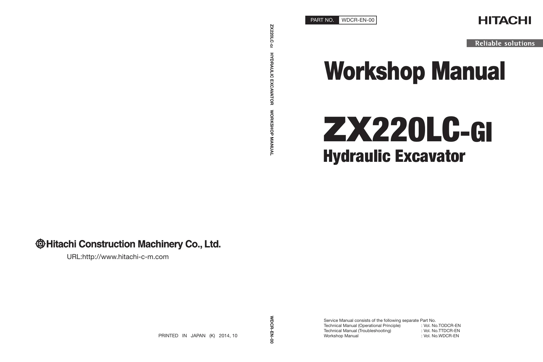


Hitachi ZX220LC-GI Hydraulic Excavator Workshop Manual 2014 – WDCR-EN-00 PDF
Original price was: $39.95.$23.95Current price is: $23.95.
Complete Hitachi ZX220LC-GI hydraulic excavator workshop manual (WDCR-EN-00, 2014) covering upperstructure, undercarriage and front attachment removal, disassembly, assembly and installation procedures with torque values and exploded views.
Description
Hitachi ZX220LC-GI Hydraulic Excavator Workshop Manual – WDCR-EN-00
This is the workshop manual for the Hitachi ZX220LC-GI hydraulic excavator, published by Hitachi Construction Machinery Co., Ltd. and identified by document number WDCR-EN-00 with a 2014 date. It is the volume written for the experienced technician who is actually removing, stripping, rebuilding and refitting the major assemblies on this machine – not a general operator handbook. Every procedure in it is organised around the physical work: lifting weights, wrench sizes, tightening torques, matching marks, sealant callouts and the order in which parts must come off and go back on.
File Details
- Manual type: Workshop Manual (Removal and Installation, Disassembly and Assembly)
- Brand: Hitachi Construction Machinery Co., Ltd.
- Model: ZX220LC-GI hydraulic excavator
- Document number: WDCR-EN-00
- Date: 2014
- Language: English
- Page count: 518 pages
- File format: PDF
Chapters Covered
The manual is divided into numbered sections, each broken into groups. The contents below follow the manual’s own structure.
- Section 3 – Upperstructure
- Group 6: Hydraulic Oil Tank – removal and installation
- Group 7: Fuel Tank – removal and installation
- Group 8: Pump Device – removal and installation, coupling, disassembly and assembly, regulator, solenoid valve, pilot pump
- Group 9: Control Valve – removal and installation, housing, 4-spool side and 5-spool side disassembly and assembly
- Group 10: Swing Device – removal and installation, disassembly and assembly, swing motor
- Group 11: Pilot Valve – left, right and travel pilot valve removal and installation, disassembly and assembly
- Group 12: Solenoid Valve – pilot shut-off solenoid valve and 3-spool solenoid valve unit
- Group 13: Signal Control Valve – removal and installation, structure
- Section 4 – Undercarriage
- Group 1: Swing Bearing – removal and installation, disassembly and assembly
- Group 2: Travel Device – removal and installation, disassembly and assembly, travel motor, brake valve, floating seal precautions
- Group 3: Center Joint – removal and installation, disassembly and assembly
- Group 4: Track Adjuster – removal and installation, disassembly and assembly
- Group 5: Front Idler – removal and installation, disassembly and assembly
- Group 6: Upper and Lower Rollers – removal, installation, disassembly and assembly
- Group 7: Track – removal and installation, master pin and link servicing
- Section 5 – Front Attachment
- Group 1: Front Attachment – removal and installation
- Group 2: Cylinder – boom, arm and bucket cylinder removal, installation, disassembly and assembly
Read as a whole, the Hitachi ZX220LC-GI workshop manual gives a technician a complete teardown and rebuild path through the machine’s heaviest and most repair-intensive assemblies. It is a procedures document rather than a theory document – the emphasis is on how to get a component off the machine safely, how to strip it on the bench, how to identify wear and sealing points, and how to reassemble it to the correct clearances and torque figures. Lifting weights are flagged at each stage, sealants and locking compounds are named where the factory applied them, and exploded illustrations carry numbered part callouts so each component in the text can be matched to a picture.
What This Workshop Manual Covers in Practice
The upperstructure section deals with the fluid and power components that sit behind and above the cab. The hydraulic oil tank and fuel tank procedures cover draining, hose and pipe disconnection, cover removal and the lifting arrangements for the tanks themselves – the fuel tank is called out at 175 kg (390 lb) and the hydraulic oil tank total oil amount at 201 L (53.1 US gal), with the fuel tank holding 400 L (106 US gal). The pump device group is the deepest part of the section: it covers separating the pump from the engine, the coupling inserts and cylinder hub, and a full bench strip of the twin pump including regulators, selector head, servo pistons, valve plates, rotors, plungers, centre shafts, bearings and the pilot pump. Bearing preload setting is described with the special tool numbers and a starting torque figure, which is the kind of detail that separates a pump rebuild that lasts from one that does not.
The control valve group covers the main valve block in detail, splitting it into the 4-spool side and the 5-spool side and working through spools, caps, springs, load check valves, boom anti-drift valves, overload relief valves, flow combiner valves, flow rate control valves and the bypass shut-out valve. The swing device group covers the swing motor and the reduction gearbox, including bearing nut tightening to 500 N.m (50 kgf.m, 370 lbf.ft) and the repeated settle-and-retorque routine that goes with it. Pilot valve coverage extends to both hand control valves and the travel pilot valve, with the shim and spring matching rules that must be respected on reassembly.
On the undercarriage side, the swing bearing procedure includes ball and support replacement – the bearing runs 111 balls and 111 supports – and the matching-mark and soft-zone rules that must be observed when refitting. The travel device group is arguably the most valuable part of the book for a machine of this class: it walks through separating the travel motor from the drum, removing the sprocket, stripping the three planetary stages, replacing the floating seal, setting the roller bearing inner races and preloading the bearing nut, and then rebuilding the travel motor itself including the brake piston, friction and separator plates, swash plate, rotor and plungers. A dedicated floating seal section explains the correct-versus-incorrect O-ring seating checks that prevent repeat oil leaks.
Also in Section 4 you get the center joint strip and reseal, the track adjuster with its spring compression tooling and the 507 mm (20.0 in) set length, the front idler with its bushing and floating seal work, the upper and lower roller procedures with their oil fill quantities, and the track group covering master pin removal, snap ring replacement direction and the track sag specification of 300 to 335 mm (11.8 to 13.2 in).
Section 5 handles the front attachment: removing the complete front attachment from the machine at 3650 kg (8050 lb), and then the boom, arm and bucket cylinders with their full internal seal kits. Cylinder work is covered step by step – set screw removal, nut and piston removal with the correct special tools, seal ring heating and installation, cushion ring clearance checks, and the head bolt torques that differ between the boom/bucket cylinders and the arm cylinder.
Who This Manual Suits
This Hitachi ZX220LC-GI workshop manual is aimed at workshops and field technicians carrying out major component overhauls, at owners running their own maintenance programme on a ZX220LC-GI, and at rebuilders who need the factory’s own disassembly order and torque figures rather than guesswork. It is particularly useful where a component has to come off the machine before it can be worked on, because every one of those procedures lists the hoses, pipes, connectors, covers and mounting hardware that must be dealt with first, along with the identification tags and capping requirements that keep a rebuild organised.
Why the Correct Procedure and Torque Values Matter Here
Excavator assemblies of this size are unforgiving. A pump reassembled with the wrong bearing preload will fail early. A swing or travel gearbox bearing nut that is not settled and retorqued to specification will lose its setting and take the bearings with it. A floating seal installed with a twisted O-ring will leak again within hours of the machine going back to work. Overload relief and main relief valves that get disturbed without being reset will change machine behaviour and can mask a genuine fault. The torque figures in this manual – 540 N.m on the swing bearing bolts, 630 N.m on the travel device mounting bolts, 500 N.m on the travel and swing bearing nuts, 460 N.m on the lower roller bolts, 90 N.m on the track adjuster valve, and the many smaller values throughout – exist because the manufacturer determined them for these joints. Following them, along with the matching marks, sealants and cleaning requirements the manual specifies, is what makes a repair hold.
Get Instant Access
IMAGES PREVIEW
The Hitachi ZX220LC-GI hydraulic excavator workshop manual is delivered as an instant PDF download after payment – there is no shipping, no waiting for a parcel and no CD to lose. You can open it on a laptop or tablet in the workshop, print the pages you need for the job in front of you, and keep the full 518-page document on file for every future repair. Whether you are pulling a pump, resealing a travel motor, resetting track tension or rebuilding a boom cylinder, this WDCR-EN-00 workshop manual gives you the disassembly sequence, the assembly tolerances and the torque values to put the machine back together correctly.

Reviews
There are no reviews yet.