
Hitachi ZX330-5G / ZX350-5G Hydraulic Excavator Workshop Manual WDDE-EN-00 – PDF Download
Original price was: $71.95.$44.95Current price is: $44.95.
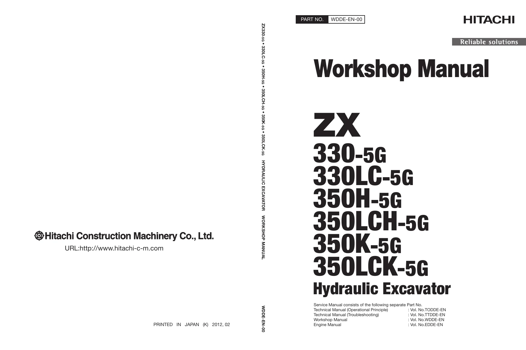
Complete 526-page Hitachi Workshop Manual for the ZX330-5G, ZX330LC-5G, ZX350H-5G, ZX350LCH-5G, ZX350K-5G and ZX350LCK-5G hydraulic excavators. Covers removal and installation, disassembly and assembly, maintenance standards, tightening torques, bleeding procedures and more. Instant PDF download.
Description
Hitachi ZX330-5G / ZX350-5G Series Hydraulic Excavator Workshop Manual — WDDE-EN-00
This is the complete Workshop Manual for the Hitachi ZX330-5G, ZX330LC-5G, ZX350H-5G, ZX350LCH-5G, ZX350K-5G and ZX350LCK-5G hydraulic excavators, published under Hitachi document number WDDE-EN-00 (dated 20161226). In Hitachi’s own words, the Workshop Manual contains the technical information needed for maintenance and repair of the machine, the tools and devices required for that work, maintenance standards, and removal / installation and assemble / disassemble procedures. This is the volume a technician reaches for once the machine is in the shop — not the one used for daily operating checks.
File Details
- Manual Type: Workshop Manual (Removal and Installation, Disassembly and Assembly)
- Brand: Hitachi
- Models Covered: ZX330-5G, ZX330LC-5G, ZX350H-5G, ZX350LCH-5G, ZX350K-5G, ZX350LCK-5G
- Language: English
- Page Count: 526
- File Format: PDF
- Document Number: WDDE-EN-00
- Date: 20161226
Chapters Covered
The manual is organised into five top-level sections, each with its own numbered groups:
- Section 1 — General
- Section 2 — Maintenance Standard
- Section 3 — Uppertructure
- Section 4 — Undercarriage
- Section 5 — Front Attachment
Section 1 — General
Section 1 opens with the practical groundwork for any teardown: precautions for disassembling and assembling, including thorough cleaning before the machine enters the shop, capping open hose and pipe ends, tagging connectors, using matching marks, and handling floating seals correctly. It then moves into tightening — a specified tightening torque chart covering M6 through M36 bolts, tightening-order diagrams for two-bolt and multi-bolt patterns, split-flange precautions, and nut-and-bolt locking methods including lock plates, split pins and wire. A painting specification and cab colour chart follow, along with bleeding air procedures for the hydraulic oil tank, hydraulic system and fuel system, the hydraulic circuit pressure release procedure, and the preparation sequence required before any inspection or maintenance work.
Section 2 — Maintenance Standard
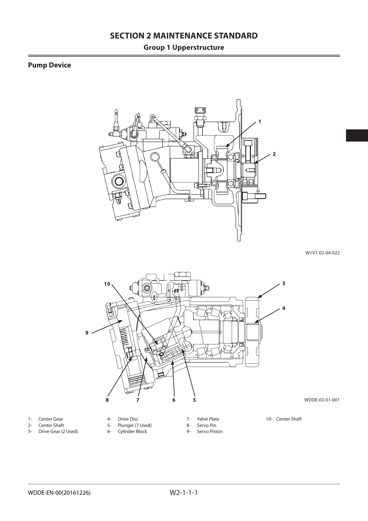
This section is the measuring-stick reference for the whole machine. It lists standard dimensions, allowable limits and remedies for the uppertructure (pump device, swing motor), the undercarriage (travel motor, sprocket, front idler, upper roller, lower roller, track, master bushing, master pin, link, grouser shoe), and the front attachment (pin and bushing dimensions, side cutters, points, arm-to-bucket and arm-to-boom connection dimensions, and cylinder rod bend and run-out limits). Values are given in mm with inch equivalents, and each row states whether the part should be built up, repaired or replaced once the allowable limit is passed.
Section 3 — Uppertructure
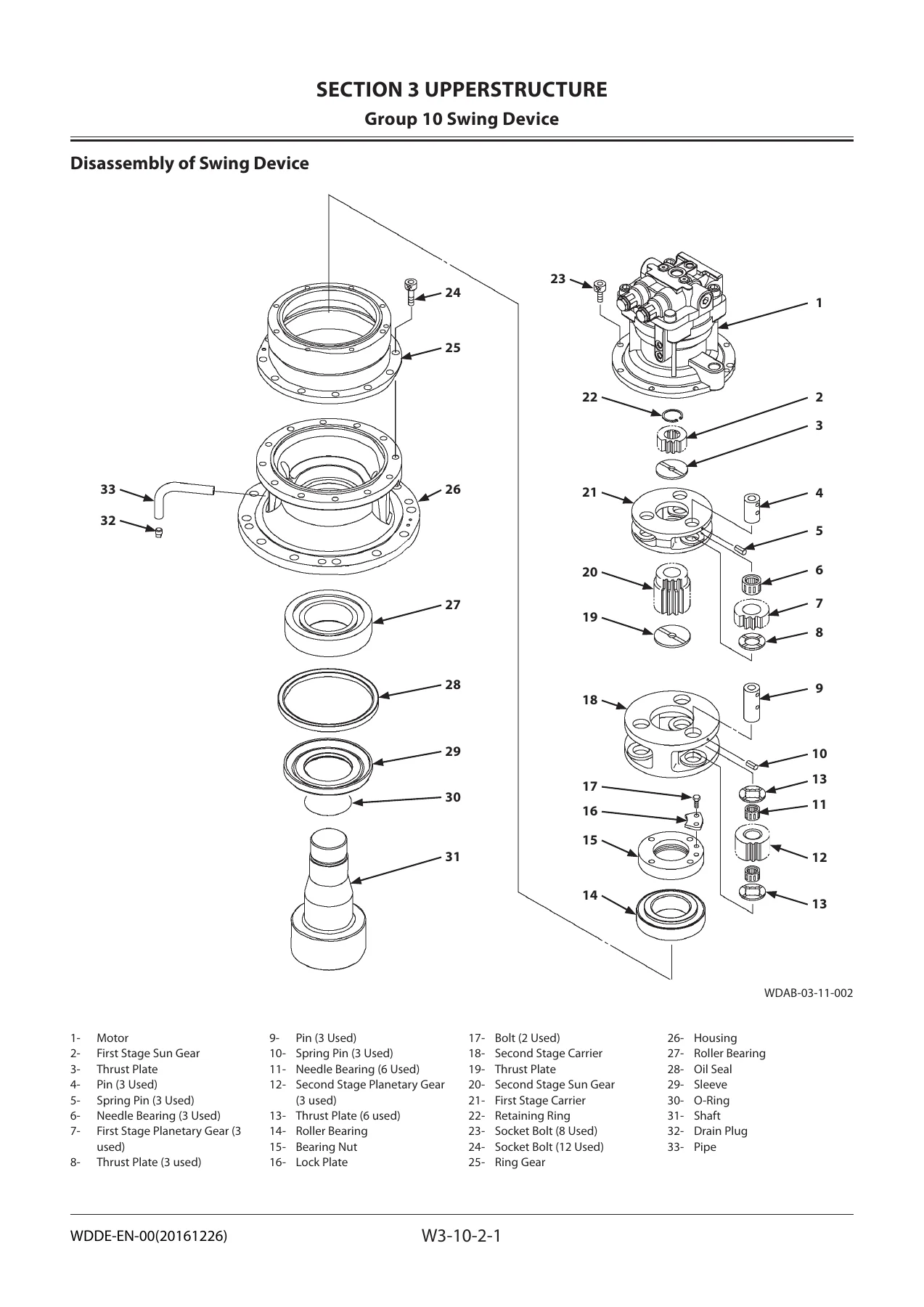
Section 3 is the largest in the manual and covers the entire upper frame assembly. It begins with cab removal and installation, cab glass dimensions and replacement procedures, then works through the counterweight, main frame, engine, radiator, oil cooler and intercooler, hydraulic oil tank, fuel tank, and the pump device — including coupling removal, pump disassembly and assembly, main pump disassembly and assembly, regulator disassembly and assembly, and pilot pump disassembly and assembly. The control valve is broken down into housing, 4-spool side and 5-spool side, with detailed assembly drawings of every spool, relief valve and check valve. The swing device, pilot valves (left and right), travel pilot valve, pilot shut-off solenoid valve, 3-spool solenoid valve unit and signal control valve each get their own removal, installation, disassembly and assembly groups.
Section 4 — Undercarriage
Section 4 covers everything below the swing bearing. It starts with swing bearing removal and installation, then disassembly and assembly of the bearing itself, followed by the travel device — removal and installation, disassembly and assembly, travel motor, brake valve, and a dedicated page of precautions for using floating seals. The centre joint, track adjuster, front idler, track adjuster disassembly and assembly, upper and lower rollers, and track removal and installation are all covered with step-by-step procedures, weights for lifting, and tightening torques for every fastener.
Section 5 — Front Attachment
The final section deals with the boom, arm and bucket. It covers removal and installation of the complete front attachment, then removal and installation of the boom cylinder, arm cylinder and bucket cylinder individually. Cylinder disassembly and assembly is split into two procedures — one for ZX330-5G Class Serial No. 040001 to 040006 and one for ZX330-5G Class Serial No. 040007 and up — reflecting a change in cylinder construction partway through the model run. Special tools, torque values and seal installation directions are listed throughout.
What This Workshop Manual Lets You Do
With this Hitachi ZX330-5G and ZX350-5G workshop manual on hand, you can pull and reinstall the cab, counterweight, main frame, engine, radiator stack, hydraulic oil tank, fuel tank, pump device, control valve, swing device, pilot valves, solenoid valves and signal control valve — and that is just Section 3. The manual also walks you through the complete teardown and rebuild of the main pumps, swing motor, travel motor, brake valve, centre joint, track adjuster, front idler, upper and lower rollers, and the boom, arm and bucket cylinders. Every procedure is paired with the tightening torque, the special tool number, the lifting weight, and the maintenance standard you need to confirm the part is still serviceable.
For shops running ZX330-5G and ZX350-5G class machines, this is the reference that keeps the work inside the manufacturer’s limits. It tells you which fasteners are single-use, where thread-locking compound goes, which seals cannot be reused, and what the allowable wear limits are before a component must be replaced rather than adjusted. The two cylinder rebuild procedures keyed to the serial number split are a good example — the manual separates them so you are not trying to apply the wrong assembly sequence to the wrong machine.
IMAGES PREVIEW
Delivered as an instant PDF download — no shipping, no waiting. Open it on a laptop, tablet or phone in the workshop, print the pages you need, and keep the file on file for the next job.


Reviews
There are no reviews yet.