★ TRUSTED BY 321,897+ PROFESSIONALS WORLDWIDE
🏒
Trusted Business
Verified & Licensed
πŸ›‘οΈ
Virus Free Files
100% Safe Downloads
πŸ”’
Secure Payment
SSL Protected
⚑
Instant Delivery
Available Immediately
Sale!

Hitachi ZX490-7G ZX490H-7G ZX490LC-7G ZX490LCH-7G ZX490LCR-7G Workshop Manual 2024 – Complete PDF Service Guide

Original price was: $39.95.Current price is: $24.95.

Complete 1049-page Hitachi workshop manual for ZX490-7G series excavators. Covers complete disassembly, assembly, maintenance standards, hydraulic systems, engine, undercarriage, and front attachment procedures. Document WJA090-EN-00, dated 2024.

⚑
Instant PDF Download
Available immediately
πŸ’Ύ
Save to Your Device
Download & keep forever
πŸ›‘οΈ
Antivirus Scanned
100% virus-free
🌍
Trusted Worldwide
175,000+ customers

Description

Hitachi ZX490-7G Series Excavator Workshop Manual – Complete PDF Service Guide

This Hitachi Workshop Manual is the definitive technical resource for the ZX490-7G, ZX490H-7G, ZX490LC-7G, ZX490LCH-7G, and ZX490LCR-7G excavators. Published under document number WJA090-EN-00 with a 2024 revision date, this 1049-page manual provides experienced technicians with the complete technical information needed to maintain and repair these machines. From general disassembly precautions through to detailed component overhaul procedures, this Hitachi ZX490-7G Workshop Manual covers every major system and procedure required for professional service work.

File Details

  • Manual Type: Workshop Manual
  • Brand: Hitachi
  • Models Covered: ZX490-7G, ZX490H-7G, ZX490LC-7G, ZX490LCH-7G, ZX490LCR-7G
  • Document Number: WJA090-EN-00
  • Date: 2024/05/31
  • Language: English
  • Page Count: 1049
  • File Format: PDF

Chapters Covered

  • Section 1 – General: Precautions for Disassembling and Assembling (floating seal handling, nylon sling use, maintenance standard terminology), Tightening (bolt types, specified torque charts, tightening order, split flange precautions, nut and bolt locking, piping joint procedures including union joints, O-ring face seals, quick couplings, screw-in connections, seal tape application, hose clamp tightening, hose connection), Painting, Bleeding Air (hydraulic system, main pump, fan pump, travel motor, swing motor, hydraulic circuit, fuel system), Preparation (inspection and maintenance positioning, hydraulic circuit pressure release, hydraulic oil tank pressure release, expansion tank pressure release)
  • Section 2 – Maintenance Standard: Upperstructure (main pump plunger and cylinder block clearances, shoe thickness, spring free length, retainer and spherical bushing dimensions, fan pump specifications, swing motor rotor and plunger clearances, friction plate thickness), Undercarriage (travel motor, sprocket dimensions with build-up welding remedies, center joint wear limits, front idler dimensions and bushing specifications, upper roller and lower roller dimensions with axle and bushing tolerances, track link pitch, grouser shoe height, master bushing, master pin, pin and bushing dimensions), Front Attachment (pin and bushing maintenance standards for all attachment pivot points, side cutter dimensions, point dimensions, standard dimensions for arm and bucket connection, arm and boom connection)
  • Section 3 – Upperstructure: Cab (removal and installation of interior parts, exterior parts, cab body, controller assembly and monitor components, cab glass dimensions, glass removal and installation procedures, upper door glass installation, upper front glass installation), Counterweight (removal and installation procedures), Main Frame (removal and installation with special tool requirements), Engine (preparation before removal, covers and related parts removal, wire harnesses and hoses removal, engine body removal and installation, related parts installation, work after installation), Radiator Assembly (removal and installation, radiator removal and installation, intercooler removal and installation, oil cooler removal and installation), Hydraulic Oil Tank (removal and installation), Fuel Tank (removal and installation), Pump Device (removal and installation, main pump disassembly and assembly, regulator for main pump disassembly and assembly, fan pump disassembly and assembly, regulator for fan pump disassembly and assembly, solenoid valve structure, pilot pump structure), Control Valve (removal and installation, housing disassembly and assembly, spool disassembly and assembly for A-side and B-side, boom 1 anti-drift valve, overload relief valves, pump 1 bypass shut-out valve, arm regeneration cut valve, bucket regeneration cut valve, check valves, auxiliary flow combiner valve, arm 2 flow rate control valve, boom flow rate control valve, load check valves, flow combiner valve, boom regenerative valve, make-up valve, plugs disassembly and assembly), Swing Device (removal and installation, swing reduction gear disassembly and assembly, swing motor disassembly and assembly), Pilot Valve (left and right removal and installation, disassembly and assembly, travel pilot valve removal and installation, disassembly and assembly), Solenoid Valve (pilot shut-off solenoid valve removal and installation, disassembly and assembly, 4-spool solenoid valve unit removal and installation for control valve side and hydraulic oil tank side, structure), Signal Control Valve (removal, installation, structure), Muffler (removal and installation), Fan Valve (removal, installation, structure), Fan Motor (removal, installation, structure), Shockless Valve (removal, installation, structure)
  • Section 4 – Undercarriage: Swing Bearing (removal, installation, disassembly, assembly), Travel Device (removal, installation, disassembly, assembly, travel motor disassembly and assembly, brake valve disassembly and assembly), Center Joint (removal, installation, disassembly, assembly, body and spindle replacement), Track Adjuster (removal, installation, disassembly, assembly with spring compression specifications), Front Idler (removal, installation, disassembly, assembly, bushing replacement), Upper and Lower Rollers (removal, installation, disassembly, assembly for both upper and lower rollers), Track (removal, installation, assembly of special tool ST1532 for master pin removal and installation)
  • Section 5 – Front Attachment: Front Attachment (removal and installation, bushing removal and installation with press-fitting plate specifications), Cylinder (boom cylinder removal, installation, disassembly, assembly with torque specifications and special tools; arm cylinder removal, installation, disassembly, assembly; bucket cylinder removal, installation, disassembly, assembly), Hose Rupture Valve (boom cylinder removal, installation, structure; arm cylinder removal, installation, structure for bottom side and rod side)

This Hitachi ZX490-7G Workshop Manual goes far beyond a simple repair guide. It is the complete service documentation for the ZX490-7G family, providing the experienced technician with all the technical information needed to perform everything from routine maintenance to complete component overhauls. The manual opens with critical safety information and general procedures for disassembling and assembling machine components, including specific precautions for handling floating seals and nylon slings. The tightening section provides comprehensive torque specifications, bolt type identification, proper tightening sequences, and detailed procedures for all types of piping joints found on these machines.

The maintenance standard section is particularly valuable, providing exact dimensions and allowable limits for every major component. Technicians can measure wear on pump plungers, cylinder blocks, shoes, sprockets, rollers, track links, and attachment pins against factory specifications to determine whether components can be reused or must be replaced. The manual specifies remedies for worn components, such as build-up welding and hand finishing for sprockets, or replacement for parts that have exceeded allowable limits. These standards allow a technician to make informed decisions about parts replacement rather than relying on guesswork.

Complete PDF Bookmark Tree

Complete Bookmarks

The complete bookmarks in the β€œHitachi ZX490-7G ZX490H-7G ZX490LC-7G ZX490LCH-7G ZX490LCR-7G Workshop Manual 2024 – Complete PDF Service Guide” are as follows:

WJA090-EN-00
INTRODUCTIONp. 3
To The Readerp. 3
Additional Referencesp. 3
Manual Compositionp. 3
Page Numberp. 3
Safety Alert Symbol and Headline Notationsp. 4
Units Usedp. 4
SYMBOL AND ABBREVIATIONp. 5
Symbols and Abbreviationsp. 5
CONTRASTING LIST OF PART NAMEp. 7
Comparative Table of Part Names between Technical Manual and Part Catalogp. 7
SAFETYp. 9
Recognize Safety Informationp. 9
Understand Signal Wordsp. 9
Follow Safety Instructionsp. 11
Prepare for Emergenciesp. 12
Wear Appropriate Clothingp. 12
Inspect Machinep. 13
General Precautions for the Cabp. 13
Use Handrail and Stepsp. 14
Adjust the Operator's Seatp. 14
Ensure Safety Before Leaving or Standing up from Operator's Seatp. 15
Fasten Your Seat Beltp. 15
Move and Operate Machine Safelyp. 16
Start the Engine Only from Operator's Seatp. 16
Jump Startingp. 17
Keep Riders off Machinep. 17
Precautions for Operationsp. 18
Perform Job Site Risk Assessment Beforehandp. 19
Install OPG (Operator Protective Guard)p. 20
Restriction of Attachment Installationp. 20
Provide Signals for Jobs Involving Multiple Machinesp. 20
Confirm Direction of Machine Travelp. 21
Drive Machine Safelyp. 22
Avoid Injury from Rollaway Accidentsp. 24
Avoid Accidents from Reversing and Swing Operationp. 25
Keep People Clear from Working Areap. 26
Never Position the Bucket Over Anyonep. 26
Avoid Undercuttingp. 27
Avoid Tippingp. 27
Never Undercut a High Bankp. 28
Dig with Cautionp. 28
Caution with an Overhead Obstaclep. 29
Avoid Power Linesp. 29
Precautions for Lightningp. 30
Never Allow Machine to Engage in Crane Workp. 30
Protect Against Flying Debris and Falling Objectp. 31
Park Machine Safelyp. 32
Handle Fluids Safelyβˆ’Avoid Firesp. 32
Practice Maintenance Safelyp. 33
Warn Others of Service Workp. 35
Support Machine Properlyp. 36
Stay Clear of Moving Partsp. 36
Prevent Parts from Flyingp. 37
Avoid Injury from Attachment Falling Accidentp. 37
Prevent Burnsp. 38
Replace Rubber Hoses Periodicallyp. 39
Avoid High-Pressure Fluidsp. 39
Prevent Firesp. 40
Check for Oil Leaks:p. 40
Check for Short circuits:p. 40
Clean up Flammable Materials:p. 41
Check Key Switch:p. 41
Check Heat Shields:p. 41
Evacuating in Case of Firep. 42
Beware of Exhaust Fumesp. 42
Precautions for Welding and Grindingp. 43
Avoid Heating Near Pressurized Fluid Linesp. 43
Avoid Applying Heat to Lines Containing Flammable Fluidsp. 43
Precautions for Handling Accumulator and Gas Damperp. 44
Remove Paint Before Welding or Heatingp. 44
Beware of Asbestos and Silica Dust and Other Contaminationp. 44
Prevent Battery Explosionsp. 45
Service Air Conditioning System Safelyp. 45
Handle Chemical Products Safelyp. 46
Dispose of Waste Properlyp. 46
Never Ride Attachmentp. 47
Precautions for Communication Terminalp. 47
Precautions for the Mobile Communication Equipmentp. 48
Notes on Protection by Operator's Station when the Machine Rolls Overp. 49
Before Returning the Machine to the Customerp. 49
SECTION AND GROUP CONTENTSp. 51
CONTENTSp. 55
GENERALp. 67
Precautions for Disassembling and Assemblingp. 69
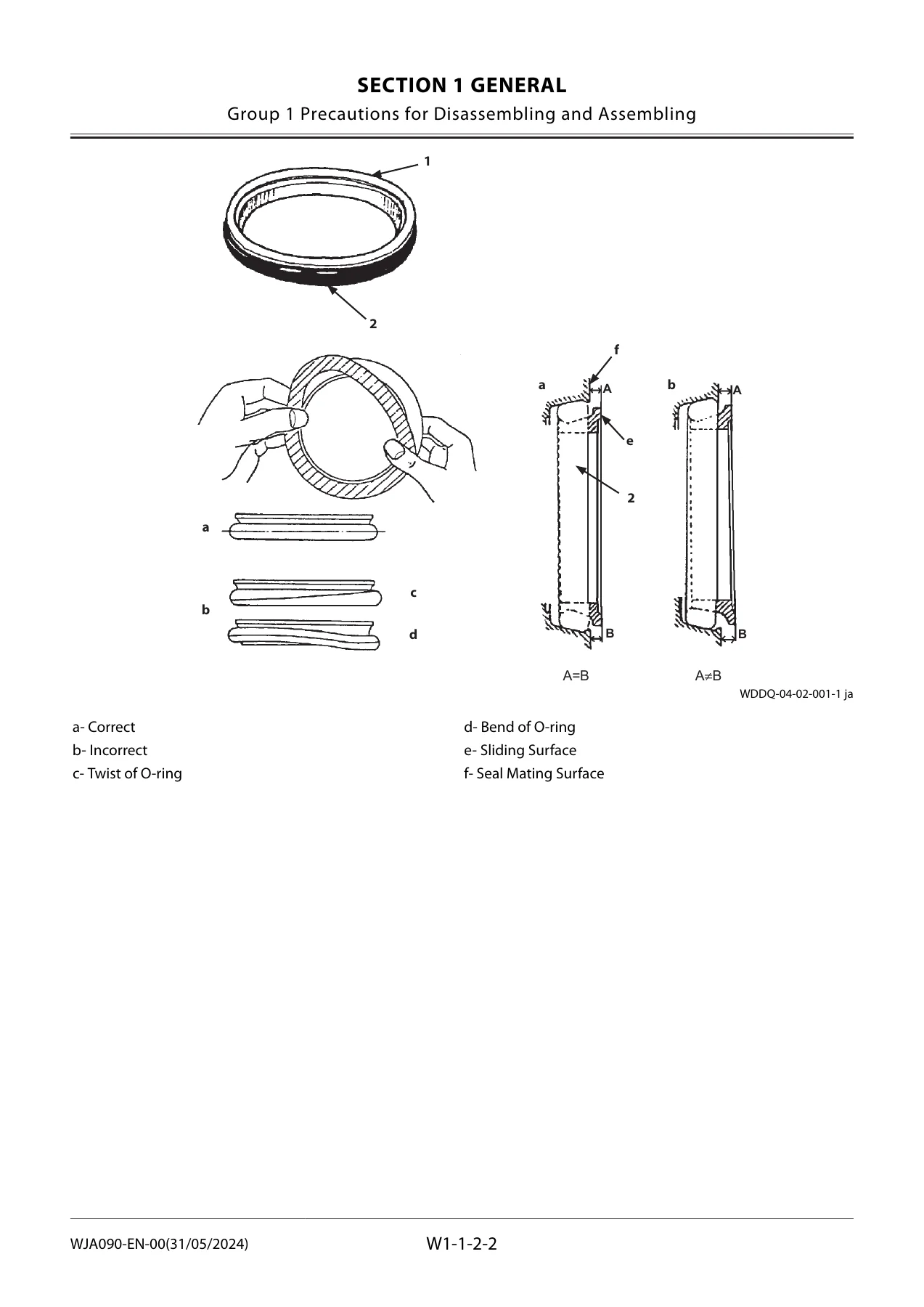
Precautions for Using Floating Sealp. 71
Precautions for Using Nylon Slingp. 73
Maintenance Standard Terminologyp. 75
Tighteningp. 77
Tightening Bolts and Nutsp. 77
Bolt Typesp. 79
Specified Tightening Torque Chartp. 81
Tightening Orderp. 83
Precautions for Spilt Flangep. 85
Nut and Bolt Lockingp. 87
Tightening Piping Jointp. 89
Union Jointp. 91
Pipe Jointp. 93
O-Ring Face Seal Jointp. 95
Quick Couplingp. 97
Screw-In Connectionp. 99
Seal Tape Applicationp. 101
Low-Pressure-Hose Clamp Tighteningp. 103
Connecting Hosep. 105
Paintingp. 107
Paintingp. 107
Bleeding Airp. 109
Bleeding Air from Hydraulic Systemp. 109
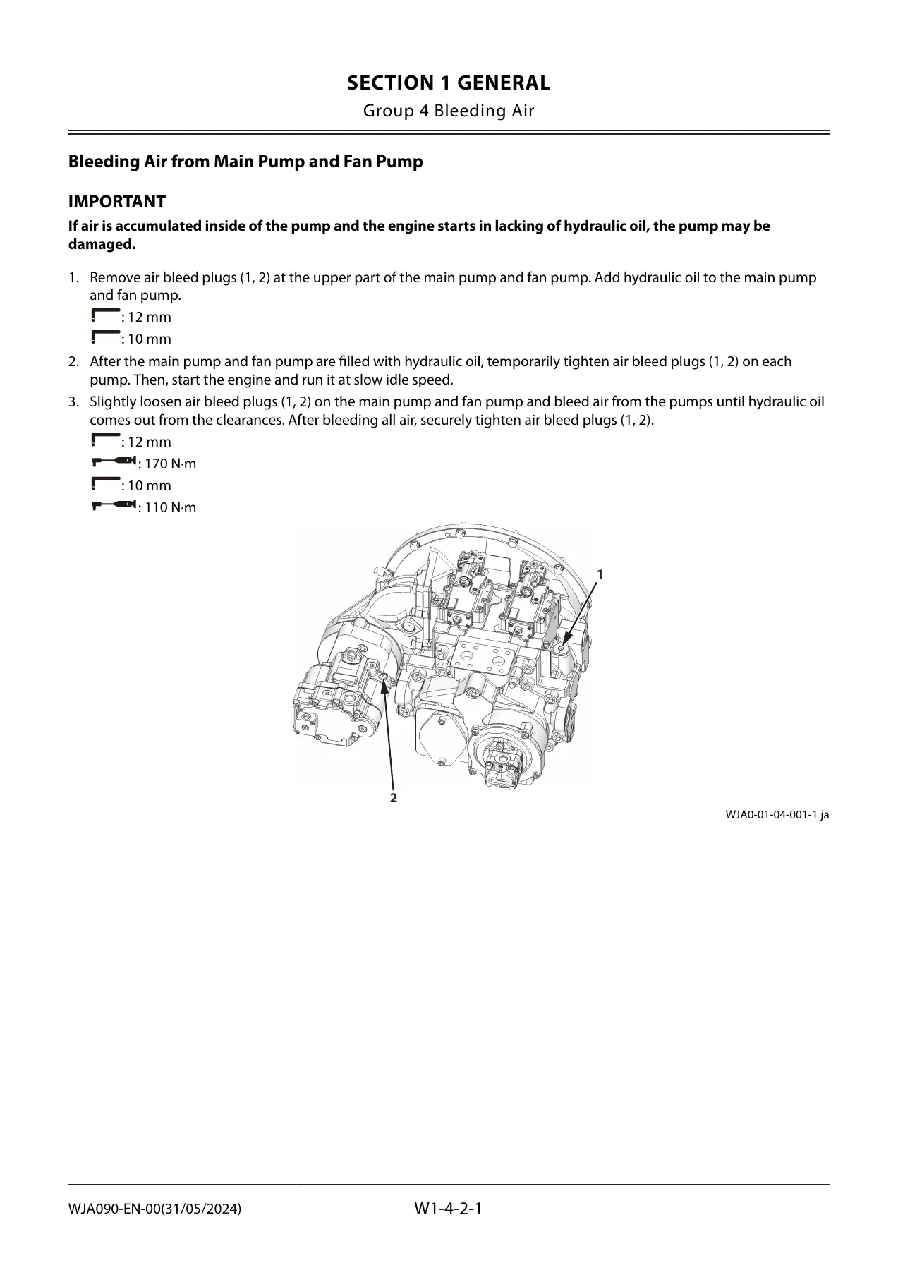
Bleeding Air from Main Pump and Fan Pumpp. 111
Bleeding Air from Travel Motor, Swing Motorp. 113
Bleeding Air from Hydraulic Circuitp. 115
Bleeding Air from Fuel Systemp. 117
Preparationp. 121
Preparation before Inspection and Maintenancep. 121
Hydraulic Circuit Pressure Release Procedurep. 123
Pressure Release from Hydraulic Oil Tankp. 125
Pressure Release from Expansion Tankp. 127
MAINTENANCE STANDARDp. 129
Upperstructurep. 131
Maintenance Standard for Main Pumpp. 131
Maintenance Standard for Fan Pumpp. 133
Maintenance Standard for Swing Motorp. 135
Undercarriagep. 139
Maintenance Standard for Travel Motorp. 139
Maintenance Standard for Sprocketp. 141
Maintenance Standard for Center Jointp. 143
Maintenance Standard for Front Idlerp. 145
Maintenance Standard for Upper Rollerp. 147
Maintenance Standard for Lower Rollerp. 149
Maintenance Standard for Trackp. 151
Front Attachmentp. 155
Maintenance Standard for Pin and Bushingp. 155
Maintenance Standard for Side Cutter (4435856, 4435857)p. 157
Maintenance Standard for Point (4350781)p. 159
Standard Dimensions for Arm and Bucket Connectionp. 161
Standard Dimensions for Arm and Boom Connectionp. 163
UPPERSTRUCTUREp. 165
Cabp. 169
Removal of Cab Interior Partsp. 169
Removal of Cab Exterior Partsp. 179
Removal of Cab Bodyp. 181
Removal of Controller Assembly and Parts around Monitorp. 185
Installation of Controller Assembly and Parts around Monitorp. 191
Installation of Cab Bodyp. 197
Installation of Cab Exterior Partsp. 201
Installation of Cab Interior Partsp. 203
Dimensions of Cab Glassp. 213
Procedure to Remove Cab Glassp. 223
Procedure to Install Cab Glassp. 225
Procedures to Install Upper Door Glassp. 233
Procedures to Install Upper Front Glassp. 235
Counterweightp. 239
Removal of Counterweightp. 239
Installation of Counterweightp. 243
Main Framep. 247
Removal of Main Framep. 247
Installation of Main Framep. 251
Enginep. 255
Preparation before Removal of Enginep. 255
Removal of Covers and Related Parts Around the Enginep. 257
Removal of Wire Harnesses and Hoses Around the Enginep. 267
Removal of Engine Bodyp. 273
Installation of Engine Bodyp. 277
Installation of Wire Harnesses and Hoses Around the Enginep. 281
Installation of Related Parts of the Enginep. 289
Work after Installation of Engine and Installation of Coversp. 295
Radiator Assemblyp. 301
Removal of Radiator Assemblyp. 301
Installation of Radiator Assemblyp. 319
Removal of Radiatorp. 337
Installation of Radiatorp. 353
Removal of Intercoolerp. 369
Installation of Intercoolerp. 373
Removal of Oil Coolerp. 377
Installation of Oil Coolerp. 393
Hydraulic Oil Tankp. 409
Removal of Hydraulic Oil Tankp. 409
Installation of Hydraulic Oil Tankp. 425
Fuel Tankp. 439
Removal of Fuel Tankp. 439
Installation of Fuel Tankp. 447
Pump Devicep. 455
Removal of Pump Devicep. 455
Installation of Pump Devicep. 467
Disassembly of Main Pumpp. 481
Assembly of Main Pumpp. 487
Disassembly of Regulator for Main Pumpp. 493
Assembly of Regulator for Main Pumpp. 495
Disassembly of Fan Pumpp. 497
Assembly of Fan Pumpp. 501
Disassembly of Regulator for Fan Pumpp. 503
Assembly of Regulator for Fan Pumpp. 505
Structure of Solenoid Valves for Main Pump and Fan Pumpp. 507
Structure of Pilot Pumpp. 509
Control Valvep. 511
Removal of Control Valvep. 511
Installation of Control Valvep. 525
Disassembly of Housingp. 539
Assembly of Housingp. 541
Disassembly of Spool (A-Side Control Valve)p. 543
Assembly of Spool (A-Side Control Valve)p. 547
Disassembly of Boom 1 Anti-Drift Valve (d) (A-Side Control Valve)p. 553
Assembly of Boom 1 Anti-Drift Valve (d) (A-Side Control Valve)p. 555
Disassembly of Overload Relief Valves (e, f, z) (A-Side Control Valve)p. 557
Assembly of Overload Relief Valves (e, f, z) (A-Side Control Valve)p. 561
Disassembly of Pump 1 Bypass Shut-Out Valve (g) (A-Side Control Valve)p. 565
Assembly of Pump 1 Bypass Shut-Out Valve (g) (A-Side Control Valve)p. 567
Disassembly of Arm Regenerative Cut Valve (h) (A-Side Control Valve)p. 569
Assembly of Arm Regeneration Cut Valve (h) (A-Side Control Valve)p. 571
Disassembly of Bucket Regeneration Cut Valve (n) (A-Side Control Valve)p. 573
Assembly of Bucket Regeneration Cut Valve (n) (A-Side Control Valve)p. 575
Disassembly of Check Valve (p) (A-Side Control Valve)p. 577
Assembly of Check Valve (p) (A-Side Control Valve)p. 579
Disassembly of Auxiliary Flow Combiner Valve (q) (A-Side Control Valve)p. 581
Assembly of Auxiliary Flow Combiner Valve (q) (A-Side Control Valve)p. 583
Disassembly of Arm 2 Flow Rate Control Valve (r) (A-Side Control Valve)p. 585
Assembly of Arm 2 Flow Rate Control Valve (r) (A-Side Control Valve)p. 587
Disassembly of Boom Flow Rate Control Valve (s) (A-Side Control Valve)p. 589
Assembly of Boom Flow Rate Control Valve (s) (A-Side Control Valve)p. 591
Disassembly of Check Valve (t) (A-Side Control Valve)p. 593
Assembly of Check Valve (t) (A-Side Control Valve)p. 595
Disassembly of Load Check Valve (Bucket Parallel Circuit) (u) (A-Side Control Valve)p. 597
Assembly of Load Check Valve (Bucket Parallel Circuit) (u) (A-Side Control Valve)p. 599
Disassembly of Flow Combiner Valve (v) (A-Side Control Valve)p. 601
Assembly of Flow Combiner Valve (v) (A-Side Control Valve)p. 603
Disassembly of Check Valve (Bucket Flow Combiner Circuit) (w) (A-Side Control Valve)p. 605
Assembly of Check Valve (Bucket Flow Combiner Circuit) (w) (A-Side Control Valve)p. 607
Disassembly of Boom Regenerative Valve (x) (A-Side Control Valve)p. 609
Assembly of Boom Regenerative Valve (x) (A-Side Control Valve)p. 611
Disassembly of Load Check Valve (Arm 2 Tandem Circuit) (y) (A-Side Control Valve)p. 613
Assembly of Load Check Valve (Arm 2 Tandem Circuit) (y) (A-Side Control Valve)p. 615
Disassembly of Make-Up Valve (Boom) (aa) (A-Side Control Valve)p. 617
Assembly of Make-Up Valve (Boom) (aa) (A-Side Control Valve)p. 619
Disassembly and Assembly of Plugs (A-Side Control Valve)p. 621
Disassembly of Spool (B-Side Control Valve)p. 623
Assembly of Spool (B-Side Control Valve)p. 627
Disassembly of Arm Rod Anti-Drift Valve (e) (B-Side Control Valve)p. 633
Assembly of Arm Rod Anti-Drift Valve (e) (B-Side Control Valve)p. 635
Disassembly of Boom Anti-Drift Valve (f) (B-Side Control Valve)p. 637
Assembly of Boom Anti-Drift Valve (f) (B-Side Control Valve)p. 639
Disassembly of Overload Relief Valves (d, y) (B-Side Control Valve)p. 641
Assembly of Overload Relief Valves (d, y) (B-Side Control Valve)p. 645
Disassembly of Auxiliary Overload Relief Valves (p, ac) (B-Side Control Valve)p. 647
Assembly of Auxiliary Overload Relief Valves (p, ac) (B-Side Control Valve)p. 651
Disassembly of Boom Overload Relief Valve (z) (B-Side Control Valve)p. 653
Assembly of Boom Overload Relief Valve (z) (B-Side Control Valve)p. 655
Disassembly of Main Relief Valve (m) (B-Side Control Valve)p. 657
Assembly of Main Relief Valve (m) (B-Side Control Valve)p. 659
Disassembly of Check Valve (Main Relief Circuit) (n) (B-Side Control Valve)p. 661
Assembly of Check Valve (Main Relief Circuit) (n) (B-Side Control Valve)p. 663
Disassembly of Pump 2 Bypass Shut-Out Valve (q) (B-Side Control Valve)p. 665
Assembly of Pump 2 Bypass Shut-Out Valve (q) (B-Side Control Valve)p. 667
Disassembly of Load Check Valves (r, s) (B-Side Control Valve)p. 669
Assembly of Load Check Valves (r, s) (B-Side Control Valve)p. 671
Disassembly of Load Check Valves (t, u) (B-Side Control Valve)p. 673
Assembly of Load Check Valves (t, u) (B-Side Control Valve)p. 675
Disassembly of Load Check Valve (Boom 2 Parallel Circuit) (v) (B-Side Control Valve)p. 677
Assembly of Load Check Valve (Boom 2 Parallel Circuit) (v) (B-Side Control Valve)p. 679
Disassembly of Arm 1 Flow Rate Control Valve (w) (B-Side Control Valve)p. 681
Assembly of Arm 1 Flow Rate Control Valve (w) (B-Side Control Valve)p. 683
Disassembly of Swing Flow Rate Control Valve (x) (B-Side Control Valve)p. 685
Assembly of Swing Flow Rate Control Valve (x) (B-Side Control Valve)p. 687
Disassembly of Load Check Valve (aa), Check Valve (ab) (B-Side Control Valve)p. 689
Assembly of Load Check Valve (aa), Check Valve (ab) (B-Side Control Valve)p. 691
Disassembly and Assembly of Plugs (B-Side Control Valve)p. 693
Swing Devicep. 695
Removal of Swing Devicep. 695
Installation of Swing Devicep. 699
Disassembly of Swing Reduction Gearp. 703
Assembly of Swing Reduction Gearp. 711
Disassembly of Swing Motorp. 719
Assembly of Swing Motorp. 723
Pilot Valvep. 727
Removal of Pilot Valve (Left)p. 727
Installation of Pilot Valve (Left)p. 733
Removal of Pilot Valve (Right)p. 739
Installation of Pilot Valve (Right)p. 745
Disassembly of Pilot Valves (Left and Right)p. 753
Assembly of Pilot Valves (Left and Right)p. 757
Removal of Travel Pilot Valvep. 761
Installation of Travel Pilot Valvep. 763
Disassembly of Travel Pilot Valvep. 765
Assembly of Travel Pilot Valvep. 769
Solenoid Valvep. 773
Removal of Pilot Shut-Off Solenoid Valvep. 773
Installation of Pilot Shut-Off Solenoid Valvep. 775
Disassembly of Pilot Shut-Off Solenoid Valvep. 777
Assembly of Pilot Shut-Off Solenoid Valvep. 779
Removal of 4-Spool Solenoid Valve Unit (Control Valve Side)p. 781
Installation of 4-Spool Solenoid Valve Unit (Control Valve Side)p. 785
Removal of 4-Spool Solenoid Valve Unit (Hydraulic Oil Tank Side)p. 787
Installation of 4-Spool Solenoid Valve Unit (Hydraulic Oil Tank Side)p. 791
Structure of 4-Spool Solenoid Valve Unitp. 793
Signal Control Valvep. 795
Removal of Signal Control Valvep. 795
Installation of Signal Control Valvep. 799
Structure of Signal Control Valvep. 803
Mufflerp. 807
Removal of Mufflerp. 807
Installation of Mufflerp. 811
Fan Valvep. 815
Removal of Fan Valvep. 815
Installation of Fan Valvep. 819
Structure of Fan Valvep. 825
Fan Motorp. 827
Removal of Fan Motorp. 827
Installation of Fan Motorp. 831
Structure of Fan Motorp. 835
Shockless Valvep. 837
Removal of Shockless Valvep. 837
Installation of Shockless Valvep. 839
Structure of Shockless Valvep. 841
UNDERCARRIAGEp. 843
Swing Bearingp. 845
Removal of Swing Bearingp. 845
Installation of Swing Bearingp. 847
Disassembly of Swing Bearingp. 851
Assembly of Swing Bearingp. 855
Travel Devicep. 857
Removal of Travel Devicep. 857
Installation of Travel Devicep. 859
Disassembly of Travel Devicep. 861
Assembly of Travel Devicep. 867
Disassembly of Travel Motorp. 875
Assembly of Travel Motorp. 879
Disassembly of Brake Valvep. 885
Assembly of Brake Valvep. 889
Center Jointp. 891
Removal of Center Jointp. 891
Installation of Center Jointp. 893
Disassembly of Center Jointp. 897
Assembly of Center Jointp. 899
Replacement of Body and Spindlep. 903
Track Adjusterp. 905
Removal of Track Adjusterp. 905
Installation of Track Adjusterp. 907
Disassembly of Track Adjusterp. 909
Assembly of Track Adjusterp. 915
Front Idlerp. 921
Removal of Front Idlerp. 921
Installation of Front Idlerp. 923
Disassembly of Front Idlerp. 925
Assembly of Front Idlerp. 929
Upper and Lower Rollersp. 933
Removal of Upper Rollerp. 933
Installation of Upper Rollerp. 935
Removal of Lower Rollerp. 939
Installation of Lower Rollerp. 943
Disassembly of Lower Rollerp. 947
Assembly of Lower Rollerp. 951
Trackp. 953
Removal of Trackp. 953
Installation of Trackp. 959
Assembly of Special Tool (ST1532) for Removal / Installation of Master Pinp. 965
FRONT ATTACHMENTp. 967
Front Attachmentp. 969
Removal of Front Attachmentp. 969
Installation of Front Attachmentp. 973
Removal of Bushingp. 977
Installation of Bushingp. 979
Cylinderp. 981
Removal of Boom Cylinderp. 981
Installation of Boom Cylinderp. 985
Disassembly of Boom Cylinderp. 989
Assembly of Boom Cylinderp. 993
Removal of Arm Cylinderp. 997
Installation of Arm Cylinderp. 1003
Disassembly of Arm Cylinderp. 1009
Assembly of Arm Cylinderp. 1013
Removal of Bucket Cylinderp. 1017
Installation of Bucket Cylinderp. 1021
Disassembly of Bucket Cylinderp. 1025
Assembly of Bucket Cylinderp. 1029
Hose Rupture Valvep. 1031
Removal of Hose Rupture Valve for Boom Cylinderp. 1031
Installation of Hose Rupture Valve for Boom Cylinderp. 1033
Structure of Hose Rupture Valve for Boom Cylinderp. 1035
Removal of Hose Rupture Valve for Arm Cylinderp. 1037
Installation of Hose Rupture Valve for Arm Cylinderp. 1041
Structure of Hose Rupture Valve for Arm Cylinder (Bottom Side)p. 1045
Structure of Hose Rupture Valve for Arm Cylinder (Rod Side)p. 1047
SERVICE MANUAL REVISION REQUEST FORMp. 1049

What This Manual Enables You to Do

With this Hitachi ZX490-7G Workshop Manual, you can confidently undertake major repairs and maintenance procedures on the ZX490-7G, ZX490H-7G, ZX490LC-7G, ZX490LCH-7G, and ZX490LCR-7G excavators. The manual provides step-by-step procedures for removing and installing the cab, counterweight, main frame, engine, radiator assembly, hydraulic oil tank, fuel tank, pump device, control valve, swing device, pilot valve, solenoid valve, signal control valve, muffler, fan valve, fan motor, and shockless valve. For each of these major components, the manual details disassembly and assembly procedures, often with exploded views and specific torque values for critical fasteners.

The hydraulic system coverage is particularly comprehensive. You can disassemble and reassemble the main pump, fan pump, and their regulators using the detailed procedures provided. The control valve section covers the A-side and B-side control valves in exhaustive detail, including the disassembly and assembly of spools, boom 1 anti-drift valve, overload relief valves, pump 1 bypass shut-out valve, arm regeneration cut valve, bucket regeneration cut valve, check valves, auxiliary flow combiner valve, arm 2 flow rate control valve, boom flow rate control valve, load check valves, flow combiner valve, boom regenerative valve, make-up valve, and all associated plugs. For each valve, the manual provides the specific procedures needed to disassemble, inspect, and reassemble the unit correctly.

The undercarriage section gives you everything needed to service the swing bearing, travel device, center joint, track adjuster, front idler, upper and lower rollers, and track. The travel device section includes complete procedures for disassembling and assembling the travel motor and brake valve, with torque specifications for all critical fasteners. The track adjuster section provides the spring compression specifications and the procedures for safely disassembling and assembling this high-energy component. The track removal and installation procedures include the assembly and use of special tool ST1532 for master pin removal and installation.

The front attachment section covers the removal and installation of the complete front attachment, as well as the disassembly and assembly of the boom, arm, and bucket cylinders. The manual provides the torque specifications for the cylinder head bolts, piston nuts, and set screws, along with the special tools required for each cylinder size. The bushing removal and installation procedures include the press-fitting plate specifications for each attachment pivot point. The hose rupture valve section provides the structure and service procedures for both the boom cylinder and arm cylinder hose rupture valves.

Beyond the component-level procedures, this Hitachi ZX490-7G Workshop Manual includes the maintenance standards that allow you to evaluate component condition and make proper repair decisions. The manual provides allowable limits for wear on pins, bushings, sprockets, rollers, track links, and hydraulic components. When a component exceeds its allowable limit, the manual specifies the remedy, whether that is replacement, build-up welding, or hand finishing. This information is essential for anyone performing professional service work on these machines.

All information in this Hitachi ZX490-7G Workshop Manual is based on the latest product information available at the time of publication. The manual includes all the technical information needed for maintenance and repair of the machine, including the tools and devices needed for maintenance and repair, maintenance standards, and removal/installation and disassemble/assemble procedures. This is the same type of information that Hitachi provides to its authorized dealers, presented in a clear, step-by-step format that experienced technicians can follow.

Why This Manual Matters

Performing repairs and maintenance on a ZX490-7G series excavator without the proper specifications and procedures can lead to costly mistakes. Overtightening or undertightening critical fasteners can cause component failure. Using the wrong torque on hydraulic fittings can lead to leaks or damaged threads. Incorrect disassembly procedures can damage precision-machined surfaces. Failure to use the correct special tools can result in injury or component damage.

IMAGES PREVIEW

Hitachi ZX490-7G ZX490H-7G ZX490LC-7G ZX490LCH-7G ZX490LCR-7G Workshop Manual 2024 - Complete PDF Service Guide β€” PDF page 111 preview
Hitachi ZX490-7G ZX490H-7G ZX490LC-7G ZX490LCH-7G ZX490LCR-7G Workshop Manual 2024 - Complete PDF Service Guide β€” PDF page 72 preview
Hitachi ZX490-7G ZX490H-7G ZX490LC-7G ZX490LCH-7G ZX490LCR-7G Workshop Manual 2024 - Complete PDF Service Guide β€” PDF page 163 preview

This Hitachi ZX490-7G Workshop Manual eliminates guesswork from every repair. Each procedure includes the torque values, clearances, and special tools required to complete the job correctly. The maintenance standards tell you exactly when a component must be replaced and when it can be reused. The exploded views help you understand how components are assembled and ensure you do not miss any parts during reassembly. The safety precautions help you avoid injury during potentially hazardous procedures.

For anyone who services these machines professionally, having the factory workshop manual is essential. Whether you are a dealer technician, an independent shop owner, or a fleet maintenance manager, this manual provides the authoritative information you need to keep ZX490-7G series excavators running reliably. The procedures are written for experienced technicians, so you can work efficiently without wading through unnecessary basic explanations.

The manual covers all aspects of the machine, from the engine and hydraulic system to the undercarriage and front attachment. You can use it to troubleshoot problems, plan repairs, order the correct parts, and perform the work correctly the first time. The maintenance standards allow you to evaluate used components during overhauls and make informed decisions about replacement versus reuse. This level of detail saves time and money on every repair job.

Instant PDF Delivery – No Shipping, No Waiting

This Hitachi ZX490-7G Workshop Manual is delivered as an instant PDF download. There is no physical book to ship, no waiting for delivery, and no shipping costs. As soon as your payment is processed, you can download the complete 1049-page manual and start using it immediately. The PDF format works on any device – desktop computer, laptop, tablet, or smartphone – so you can access the information whether you are in the office planning a repair or in the shop performing the work.

The PDF format allows you to search for specific information, print the pages you need for reference in the shop, and zoom in on detailed illustrations. You can keep the manual on multiple devices for convenience, and you never have to worry about losing or damaging a physical book. The PDF is the complete manual with all sections, chapters, illustrations, and specifications included.

Whether you are performing a routine maintenance procedure, troubleshooting a hydraulic problem, or planning a complete component overhaul, this Hitachi ZX490-7G Workshop Manual provides the information you need in a convenient, searchable, printable format. Download your copy today and have the complete factory service information for ZX490-7G, ZX490H-7G, ZX490LC-7G, ZX490LCH-7G, and ZX490LCR-7G excavators at your fingertips.
Reviews

There are no reviews yet.

Be the first to review “Hitachi ZX490-7G ZX490H-7G ZX490LC-7G ZX490LCH-7G ZX490LCR-7G Workshop Manual 2024 – Complete PDF Service Guide”

What Our Customers Say

β˜…β˜…β˜…β˜…β˜… Live reviews from customers
Loading customer reviews...
0
    0
    Your Cart
    Your cart is emptyReturn to Shop
    πŸ›’
    Recently Purchased
    πŸ•’ verified order