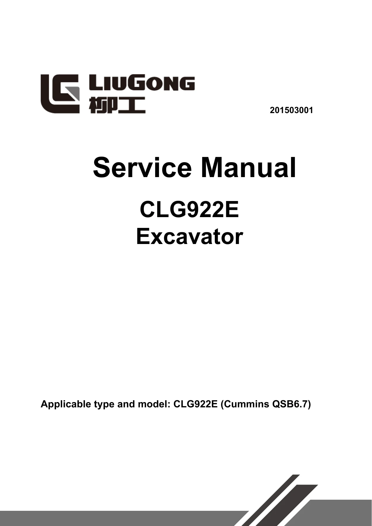
LiuGong CLG922E Excavator Service Manual 201503001 – Cummins QSB6.7 Workshop Repair Guide
$39.95 Original price was: $39.95.$24.95Current price is: $24.95.
Complete 981-page LiuGong CLG922E Excavator Service Manual covering the Cummins QSB6.7 engine, hydraulic systems, undercarriage, electrical diagnostics, fault codes, removal and installation procedures, and full specifications for professional repair and maintenance.
Description
LiuGong CLG922E Excavator Service Manual — Complete Workshop Coverage
This LiuGong CLG922E Excavator Service Manual (document 201503001) is the complete technical workshop guide for the CLG922E model equipped with the Cummins QSB6.7 diesel engine. Spanning 981 pages, this service manual gives technicians, fleet maintenance crews, and heavy equipment mechanics the full scope of procedures, specifications, and diagnostic information needed to service, troubleshoot, and overhaul the machine. From routine maintenance intervals to complete component disassembly, the manual is structured to support both the technical guide reference and the workshop guide execution.
File Details
- Manual Type: Service Manual / Workshop Repair Guide
- Brand: LiuGong
- Model: CLG922E
- Applicable Engine: Cummins QSB6.7
- Document Number: 201503001
- Version/Revision: CLG922EIII, March 20, 2015
- Language: English
- Page Count: 981
- File Format: PDF
Chapters Covered
- 1. Safety
- Safety precautions, compressed air, high-pressure solution, safe disposal of waste liquid
- Accumulator precautions, asbestos, prevention of extruding or cutting off, burns, coolant, oil, battery
- Fire and explosion protection, diethyl ether, piping/pipe and hose, fire extinguisher and first-aid kit
- Prevention of injury by thunder, cab protector, inner space of cab, precautions for accessories
- Lifting and matching operations, mobile crane, bridge crane, selection of rope
- 2. Foreword
- How to read the manual, composition of service manual, other reference manuals, user’s guidance
- Marking of revised version, standard of general torque, unit conversion table
- Cable identification methods, wire number, wire categories, color abbreviation code, wire specification
- Coating materials, weight table, oils use specifications
IMAGES PREVIEW
- 3. Structural Function and Maintenance
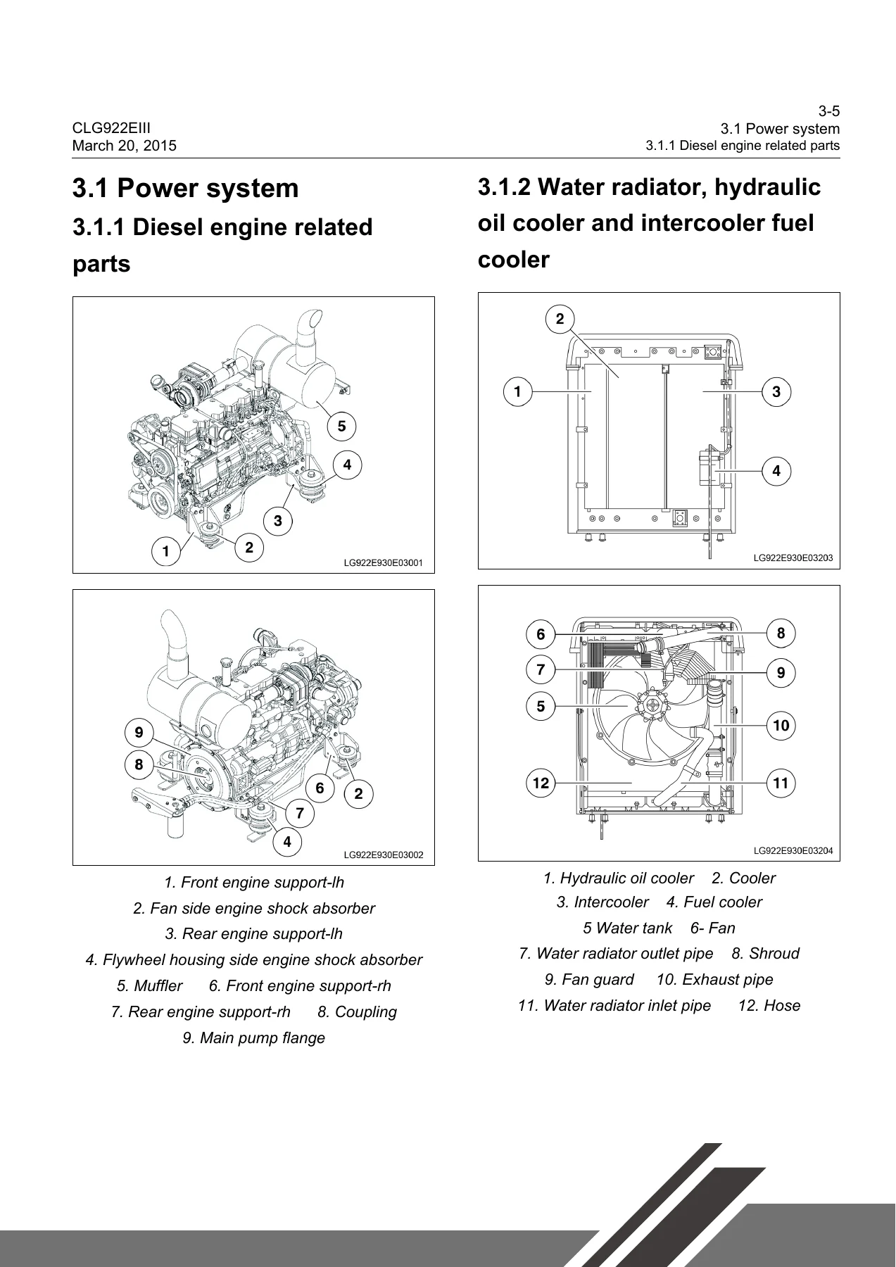
- Power system: diesel engine related parts, water radiator, hydraulic oil cooler, intercooler, fuel cooler
- Undercarriage system: track frame, tensioner, idler, carrier roller, track roller, sprocket, track
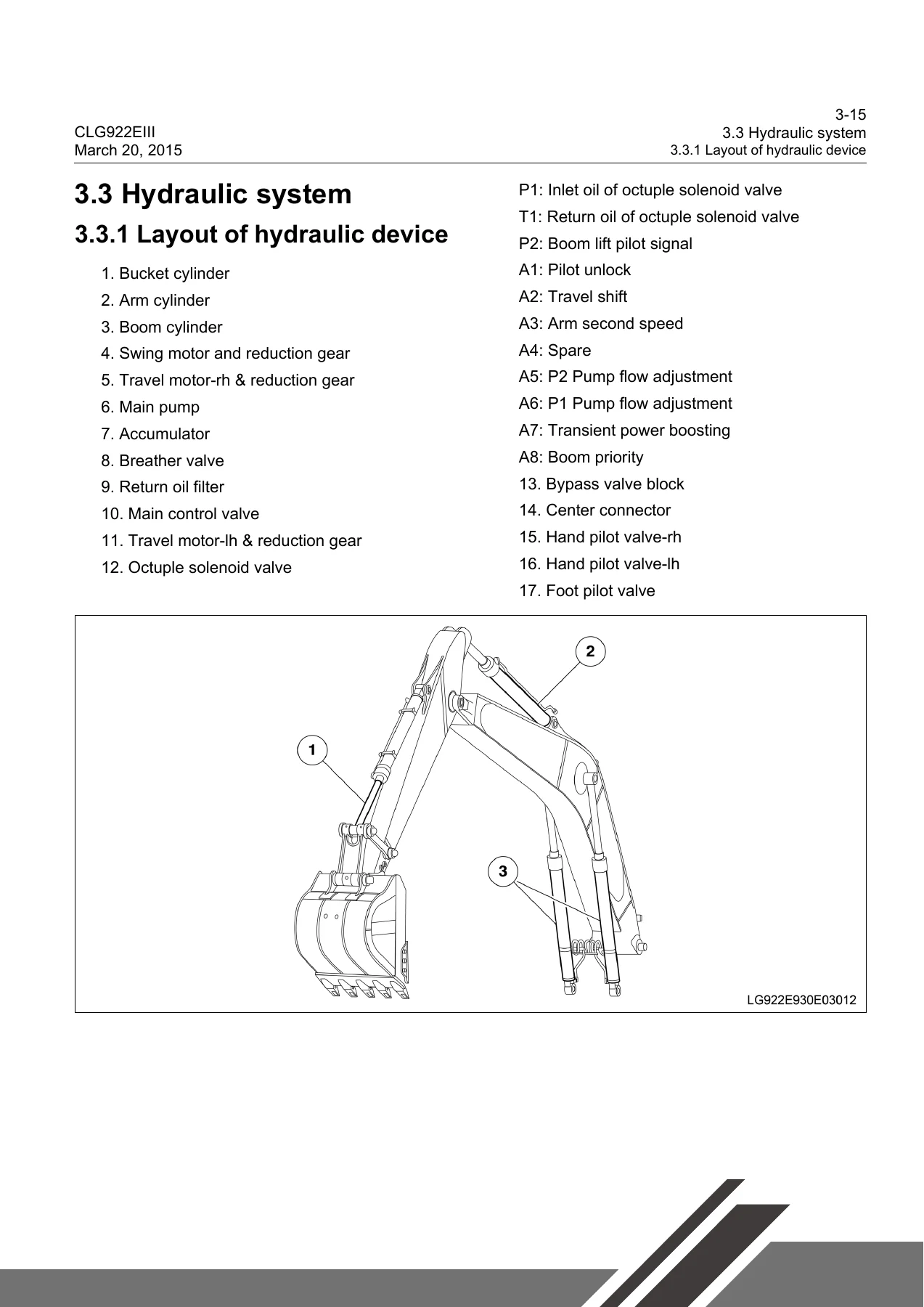
- Hydraulic system: layout, main pump, main control valve, center connector, explosion-proof valve, hand pilot valve, foot pilot valve, cushion valve, octuple solenoid valve, travel motor & reduction gear, swing motor & reduction gear, cylinder, hydraulic oil tank
- Hydraulic working principle: main hydraulic circuit, pilot circuit, negative flow control, boom/arm/bucket/swing/travel circuits
- Work implement: component sizes, arm part, bucket part
- Air conditioning system: layout of A/C pipeline
- Electrical system: engine control, display system, LCD, key panel, software, user mode, electrical control system, work modes, auto idling, power boosting, overheating protection, travel speed control, descriptions of partial circuits
- 4. Parameters
- Basic parameters: main technical parameters, dimension drawing, complete vehicle parameters, components parameters, scope of work
- Performance parameters of diesel engine
- Performance parameters of complete machine
- 5. Testing and Adjusting
- Performance test of complete machine: diesel engine speed, travel speed, running speed, travel deflection, swing parking brake angle, revolving speed, swing bearing clearance, cylinder action time, cylinder settlement, control lever operating force/stroke, boom lifting and swing action, pilot pressure, secondary pilot pressure, solenoid proportional valve output pressure, main relief valve setting pressure
- Other tests: valve clearance adjustment, crankcase blow-by measurement, oil pressure measurement, track tension measurement and adjustment, negative flow pressure N1/N2 inspection and adjustment, release of remaining pressure, exhaust of various devices, diode inspection, compressor belt tensioner adjustment, travel motor and reduction gear performance test
- 6. Fault Diagnosis
- Precautions for fault diagnosis, basic fault detection before maintenance
- Classification of faults: DTC, electrical system faults, hydraulic and mechanical system faults
- DTC codes: battery voltage, charging system, engine oil pressure, pilot pressure switches, air filter, engine speed, coolant temperature, hydraulic oil temperature, fuel level, water-in-fuel, sensor power, pump proportional solenoid valve, attachment confluent solenoid valve, travel speed solenoid, flattening solenoid valve, digging solenoid valve, flow adjusting solenoid valves, power boosting solenoid valve, travel lifting solenoid valve, battery relay, auto preheating relay, start cut-off relay, travel alarm, pump pressure sensors, negative flow pressure sensors, pump pressure-reducing valve sensor, actuator feedback, controller heartbeat, CAN bus communication, accelerator knob, fuel pump relay, GPS/GSM/GPRS faults, fan reversing/drive solenoid valves
- Electrical system fault diagnosis: battery undervoltage, abnormal battery, automatic slowdown failed, engine start fault, engine shutdown during operation, engine non-shutdown, preheater fault, all implements/revolving/travel unable to move, display screen showing nothing, incorrect hydraulic oil temperature display, fuel gauge unable to display correct value, windshield wiper unable to work, A/C panel unable to display, no wind or abnormal air volume, poor A/C refrigeration, A/C alarm codes, travel alarm unable to sound
- Hydraulic and mechanical system fault diagnosis: excessive braking angle for slewing stop, abnormal noise of pump mounting position, no responses for all operations, hydraulic oil emulsification, abnormal hydraulic oil temperature rise, slewing abnormally, no response for slewing single direction, rotation unable to stop, fail to actuate unilateral travel mechanism, travel deviation, slow speed of boom/arm/bucket, weak actions of boom/arm/bucket, significantly reduced engine speed or engine stalling
- 7. Removal and Installation
- Overview
- Power system: diesel engine as, hydraulic oil cooler, intercooler, water radiator, fuel tank as, injector, engine front seal, engine rear seal, cylinder head as, fuel cooler
- Undercarriage system: track roller, carrier roller, track as, sprocket, idler as and tensioner as, revolving frame, swing bearing
- Covering parts: engine hood, counterweight
- Hydraulic system: center connector as, hydraulic oil tank, main control valve as, main pump as, foot pilot valve as, hand pilot valve as, travel motor & reduction gear, swing motor & reduction gear
- Work implement: bucket, link and lever, arm, boom, work implement assembly, bucket cylinder as, arm cylinder as, boom cylinder as, cylinder disassembly and assembly
- Air conditioning system: A/C compressor as, A/C evaporator as
- Cab: removal and installation, floor plate as
Complete PDF Bookmark TreeComplete Bookmarks
The complete bookmarks in the “LiuGong CLG922E Excavator Service Manual 201503001 – Cummins QSB6.7 Workshop Repair Guide” are as follows:
+1 Safetyp. 5
+1.1 Safety precautionsp. 8
Compressed airp. 10High-pressure solutionp. 10Safe disposal of waste liquidp. 11Precautions for accumulatorp. 12Asbestosp. 12Prevention of extruding or cutting offp. 13Prevention of burnsp. 14Coolantp. 14Oilp. 14Batteryp. 15Protection for fire and explosionp. 15Diethyl etherp. 16Piping, pipe and hosep. 16Fire extinguisher and first-aid kitp. 17Prevention of injured by thunderp. 17Cab protectorp. 18Inner space of cabp. 18Precautions for accessoriesp. 19+1.2 Precautions for lifting and matching operationsp. 20
Precautions for operating mobile cranep. 21Precautions for operating bridge cranep. 21Selection of ropep. 22+2 Forewordp. 23
+2.1 How to read the Manualp. 25
Composition of service manualp. 25Other reference manualsp. 25User's guidancep. 252.2 Marking of revised versionp. 262.3 Standard of general torquep. 272.4 Unit conversion tablep. 31+2.5 Cable identification methodsp. 32
Wire No.p. 32Wire categoriesp. 33Color abbreviation codep. 33Wire specificationp. 34Circuit type and color abbreviation codep. 342.6 Coating materialsp. 352.7 Weight tablep. 362.8 Oils use specificationsp. 37+3 Structural function and maintenancep. 39
+3.1 Power systemp. 43
3.1.1 Diesel engine related partsp. 433.1.2 Water radiator, hydraulic oil cooler and intercooler fuel coolerp. 43+3.2 Undercarriage systemp. 44
3.2.1 Track frame and tensionerp. 443.2.2 Idlerp. 453.2.3 Carrier rollerp. 473.2.4 Track rollerp. 493.2.5 Sprocketp. 513.2.6 Trackp. 52+3.3 Hydraulic systemp. 54
3.3.1 Layout of hydraulic devicep. 543.3.2 Hydraulic elementsp. 563.3.3 Hydraulic working principlep. 181+3.4 Work implementp. 220
3.4.1 Sizes of componentsp. 2203.4.2 Arm partp. 2233.4.3 Bucket partp. 225+3.5 Air conditioning systemp. 227
3.5.1 Layout diagram of A/C pipelinep. 227+3.6 Electrical systemp. 228
3.6.1 Engine controlp. 2283.6.2 Display systemp. 2293.6.3 Electrical control systemp. 2443.6.4 Descriptions of partial circuitsp. 262+4 Parametersp. 272
+4.1 Basic parametersp. 274
Main technical parametersp. 274Dimension drawingp. 274Complete vehicle parametersp. 275Components parametersp. 276Scope of workp. 2794.2 Performance parameters of diesel enginep. 2814.3 Performance parameters of complete machinep. 282+5 Testing and adjustingp. 286
+5.1 Performance test of complete machinep. 288
5.1.1 Diesel engine speedp. 2905.1.2 Travel speed (idle speed)p. 2915.1.3 Running speed (actual testing speed)p. 2925.1.4 Travel deflectionp. 2935.1.5 Swing parkig brake anglep. 2945.1.6 Revolving speedp. 2965.1.7 Swing bearing clearancep. 2975.1.8 Action time of cylinderp. 2995.1.9 Cylinder settlementp. 3025.1.10 Operating force of control leverp. 3035.1.11 Control lever strokep. 3045.1.12 Boom lifting and swing actionp. 3045.1.13 Pilot pressurep. 3055.1.14 Secondary pilot pressurep. 3065.1.15 Output pressure of solenoid proportional valvep. 3085.1.16 Setting pressure of main relief valvep. 309+5.2 Other testsp. 318
5.2.1 Adjustment of valve clearancep. 3185.2.2 Measurement of blow-by of crankcasep. 3255.2.3 Measurement of oil pressurep. 3325.2.4 Measurement and adjustment of track tensionp. 3355.2.5 Inspection and adjustment of minus feedback pressure N1p. 3375.2.6 Inspection and adjustment of minus feedback pressure N2p. 3395.2.7 Release of remaining pressure in hydraulic oil linesp. 3405.2.8 Exhaust of various devicesp. 3425.2.9 Inspection procedure of diodesp. 3455.2.10 Adjustment of compressor belt tensionerp. 3465.2.11 Performance test of travel motors and reduction gearsp. 347+6 Fault diagnosisp. 350
6.1 Precautions for fault diagnosisp. 3566.2 Basic fault detection before maintenancep. 3576.3 Classification of faultsp. 360+6.4 DTCp. 362
6.4.1 DTC 101001 Extremely low battery voltagep. 3626.4.2 DTC 101003 High battery voltagep. 3696.4.3 DTC 101017 Low battery voltagep. 3736.4.4 DTC 111001 System charging faultp. 3796.4.5 DTC 121015 Engine oil pressure switch OFFp. 3826.4.6 DTC 121018 Low engine oil pressurep. 3856.4.7 DTC 121305 Hand pilot pressure switch OFFp. 3876.4.8 DTC 121405 Foot pilot pressure switch OFFp. 3916.4.9 DTC 121604 Air filter switch shorted to the groundp. 3956.4.10 DTC 121615 Air filter cloggingp. 3986.4.11 DTC 131000 High engine speedp. 4006.4.12 DTC 131005 Engine speed sensor faultp. 4036.4.13 DTC 131100 Extremely high coolant temperaturep. 4066.4.14 DTC 131103 Coolant temperature sensor voltage above the range valuep. 4086.4.15 DTC 131104 Coolant temperature sensor voltage below the range valuep. 4116.4.16 DTC 131115 High coolant temperaturep. 4146.4.17 DTC 131116 High coolant temperaturep. 4166.4.18 DTC 1131200 Extremely high hydraulic oil temperaturep. 4186.4.19 DTC 131203 Hydraulic oil temperature sensor voltage above the range valuep. 4206.4.20 DTC 131204 Hydraulic oil temperature sensor voltage below the range valuep. 4236.4.21 DTC 131215 High hydraulic oil temperaturep. 4266.4.22 DTC 131216 Extremely high hydraulic oil temperaturep. 4286.4.23 DTC 131303 Fuel level sensor voltage above the range valuep. 4306.4.24 DTC 131304 Fuel level sensor shorted to the groundp. 4356.4.25 DTC 131317 Low fuel levelp. 4396.4.26 DTC 131603 Water-in-fuel sensor voltage above the range valuep. 4426.4.27 DTC 131604 Water-in-fuel sensor voltage below the range valuep. 4456.4.28 DTC 131605 Water-in-fuel sensor open-circuitedp. 4486.4.29 DTC 131615 Water-in-fuelp. 4516.4.30 DTC 131703 Sensor power (5V) shorted to the batteryp. 4536.4.31 DTC 131704 Sensor power (5V) shorted to the groundp. 4556.4.32 DTC 141005 Pump proportional solenoid valve feedback open-circuitedp. 4586.4.33 DTC 141006 Pump proportional solenoid valve feedback overcurrentp. 4616.4.34 DTC 141104 Pump proportional solenoid valve shorted to the groundp. 4646.4.35 DTC 141105 Pump proportional solenoid valve open- circuited or shorted to the batteryp. 4676.4.36 DTC 151004 Attachment confluent solenoid valve shorted to the groundp. 4706.4.37 DTC 151005 Attachment confluent solenoid valve open- circuited or shorted to the batteryp. 4736.4.38 DTC 151204 A2 Travel speed solenoid shorted to the groundp. 4766.4.39 DTC 151205 A2 Travel speed solenoid open-circuited or shorted to the batteryp. 4796.4.40 DTC 151304 A3 Flattening solenoid valve shorted to the groundp. 4836.4.41 DTC 151305 A3 Flattening solenoid valve open- circuited or shorted to the batteryp. 4866.4.42 DTC 151404 A8 Digging solenoid valve shorted to the groundp. 4906.4.43 DTC 151405 A8 Digging solenoid valve open-circuited or shorted to the batteryp. 4936.4.44 DTC 151504 A5 Flow adjusting solenoid shorted to the groundp. 4976.4.45 DTC 151505 A5 Flow adjusting solenoid valve open- circuited or shorted to the batteryp. 5006.4.46 DTC 151605 A6 Flow adjusting solenoid open-circuited or shorted to the batteryp. 5046.4.47 DTC 151704 A7 Transient power boosting solenoid valve shorted to the groundp. 5086.4.48 DTC 151705 A7 Transient power boosting solenoid valve open-circuited or shorted to the batteryp. 5116.4.49 DTC 151804 A4 Travel lifting solenoid valve shorted to the groundp. 5156.4.50 DTC 151805 A4 Travel lifting solenoid valve open-circuited or shorted to the batteryp. 5186.4.51 DTC 151905 A5 or A6 solenoid valve feedback open- circuitedp. 5226.4.52 DTC 151906 A5 or A6 solenoid valve feedback overcurrentp. 5256.4.53 DTC 171004 Battery relay shorted to the groundp. 5286.4.54 DTC 171104 Auto preheating relay shorted to the groundp. 5316.4.55 DTC 171105 Auto preheating relay open-circuited or shorted to the batteryp. 5356.4.56 DTC 171204 Start cut-off relay shorted to the groundp. 5396.4.57 DTC 171205 Start cut-off output open-circuited or shorted to the batteryp. 5436.4.58 DTC 201004 Travel alarm shorted to the groundp. 5476.4.59 DTC 211003 P1 pump pressure sensor voltage above the range valuep. 5506.4.60 DTC 211004 P1 pump pressure sensor voltage below the range valuep. 5536.4.61 DTC 211003 P2 pump pressure sensor voltage above the range valuep. 5566.4.62 DTC 211104 P2 pump pressure sensor voltage below the range valuep. 5596.4.63 DTC 211203 N1 negative flow pressure sensor voltage above the range valuep. 5626.4.64 DTC 211204 N1 negative flow pressure sensor voltage below the range valuep. 5656.4.65 DTC 211303 N2 negative flow pressure sensor voltage above the range valuep. 5686.4.66 DTC 211304 N2 negative flow pressure sensor voltage below the range valuep. 5716.4.67 DTC 211316 High N2 negative flow pressurep. 5746.4.68 DTC 211403 Pump pressure-reducing valve sensor voltage above the range valuep. 5766.4.69 DTC 211404 Pump pressure-reducing valve sensor voltage below the range valuep. 5796.4.70 DTC 221001 Actuator feedback voltage below the range valuep. 5826.4.71 DTC 221003 Actuator feedback voltage above the range valuep. 5856.4.72 DTC 221007 Actuator getting stuckp. 5886.4.73 DTC 221013 Actuator outside the calibrated rangep. 5906.4.74 DTC 221104 Actuator AC1 terminal shorted to the groundp. 5946.4.75 DTC 221204 Actuator AC2 terminal shorted to the groundp. 5976.4.76 DTC 221305 Actuator AC1 terminal open-circuitedp. 6006.4.77 DTC 221306 Actuator AC1 overcurrentp. 6036.4.78 DTC 221405 Actuator AC2 terminal open-circuitedp. 6066.4.79 DTC 221406 Actuator AC2 overcurrentp. 6096.4.80 DTC 231012 Abnormal controller heartbeatp. 6126.4.81 DTC 231014 CAN bus communication errorp. 6146.4.82 DTC 241014 Accelerator knob outside the measurement rangep. 6166.4.83 DTC 251004 Fuel pump relay shorted to the groundp. 6196.4.84 DTC 251005 Fuel pump relay open-circuited or shorted to the batteryp. 6236.4.85 DTC 261011 GPS Antenna faultp. 6276.4.86 DTC 261111 GPS Module faultp. 6286.4.87 DTC 261211 GSM Signal faultp. 6286.4.88 DTC 261311 GPRS Connection faultp. 6296.4.89 DTC 261411 SIM card read faultp. 6306.4.90 DTC 261512 Abnormal GPS heartbeatp. 6316.4.91 DTC 261611 Level-1 automatic locking, abnormal GPS heartbeat, excavator restricted for usep. 6336.4.92 DTC 261614 Level-1 forced locking, overdue payment, excavator restricted for usep. 6356.4.93 DTC 261711 Level-2 automatic locking, abnormal GPS heartbeat, excavator restricted for usep. 6366.4.94 DTC 261714 Level-2 forced locking, overdue payment, excavator restricted for usep. 6386.4.95 DTC 261814 Please pay the due loan promptlyp. 6386.4.96 DTC 271304 Fan reversing solenoid valve shorted to the groundp. 6396.4.97 DTC 271305 Fan reversing solenoid valve open- circuited or shorted to the batteryp. 6426.4.98 DTC 271404 Fan drive solenoid valve shorted to the groundp. 6456.4.99 DTC 271405 Fan drive solenoid valve open-circuited or shorted to the batteryp. 6486.4.100 DTC 271505 Fan drive solenoid valve feedback open- circuitedp. 6516.4.101 DTC 271505 Fan drive solenoid valve feedback overcurrentp. 654+6.5 Fault diagnosis of electrical systemp. 657
6.5.1 E1-Troubleshooting for battery undervoltagep. 6576.5.2 E2-Troubleshooting for abnormal batteryp. 6596.5.3 E3-Automatic slowdown failedp. 6616.5.4 E4-Engine start faultp. 6646.5.5 E5-Engine shutdown during operationp. 6746.5.6 E6-Engine non-shutdownp. 6776.5.7 E7-Preheater faultp. 6806.5.8 E8-All the work implements, revolving and travel unable to movep. 6856.5.9 E9-Display screen showing nothingp. 6906.5.10-Incorrectly displayed hydraulic oil temperaturep. 6936.5.11 E11-Fuel gauge unable to display correct valuep. 6966.5.12 E12-Windshield wiper uable to workp. 7026.5.13 E13-A/C panel unable to displayp. 7066.5.14 E14-No wind or abnormal air volume of air conditionerp. 7116.5.15 E15-Poor A/C refrigerationp. 7136.5.16 E16-Abnormal alarm of the A/C E11 – Internal sensor wire brokenp. 7166.5.17 E17-Abnormal alarm of the A/C E12- Internal sensor short-circuitedp. 7176.5.18 E18-Abnormal alarm of the A/C E15 – Water temperature sensor wire brokenp. 7186.5.19 E19-Abnormal alarm of the A/C E16 – Water temperature sensor short-circuitedp. 7206.5.20 E20-Abnormal alarm of the A/C E180 – Insolation sensor short-circuitedp. 7226.5.21 E21-Abnormal alarm of the A/C E43 – Abnormal outlet ventilation doorsp. 7246.5.22 E22-Abnormal alarm of the A/C E44 – Abnormal the air mixing doorp. 7266.5.23 E23-Travel alarm unable to soundp. 728+6.6 Fault diagnosis of the hydraulic system and mechanical systemp. 731
6.6.1 System table of the hydraulic system and mechanical systemp. 7316.6.2 H1-Excessive barking angle for slewing stopp. 7326.6.3 H2-Abnormal noise of pump mounting positionp. 7336.6.4 H3-No responses for all operations when starting the enginep. 7346.6.5 H4-Hydraulic oil emulsificationp. 7356.6.6 H5-Abnormal hydraulic oil temperature risep. 7366.6.7 H6-Slewing abnormally to left and right directionsp. 7376.6.8 H7-No response for slewing single direction operationp. 7386.6.9 H8-Rotation unable to stopp. 7396.6.10 H9-Fail to actuate unilateral travel mechanismp. 7406.6.11 H10-Travel deviationp. 7416.6.12 H11-Slow speed of the boom, arm or bucketp. 7426.6.13 H12-Weak actions of the boom, arm or bucketp. 7436.6.14 H13-Significantly reduced engine speed or engine stallingp. 744+7 Removal and installationp. 746
7.1 Overviewp. 748+7.2 Power systemp. 749
7.2.1 Removal and installation of diesel engine asp. 7497.2.2 Removal and installation of hydraulic oil coolerp. 7557.2.3 Removal and installation of intercoolerp. 7587.2.4 Removal and installation of water radiatorp. 7617.2.5 Removal and installation of fuel tank asp. 7637.2.6 Removal and installation of injectorp. 7667.2.7 Removal and installation of engine front sealp. 7707.2.8 Removal and installation tools of engine rear sealp. 7747.2.9 Removal and installation of cylinder head asp. 7807.2.10 Removal and installation of fuel coolerp. 784+7.3 Undercarriage systemp. 785
7.3.1 Removal and installation of track rollerp. 7857.3.2 Removal and installation of carrier rollerp. 7867.3.3 Removal and installation of track asp. 7877.3.4 Removal and installation of sprocketp. 7887.3.5 Removal and installation of idler as and tensioner asp. 7897.3.6 Removal and installation of revolving framep. 7907.3.7 Removal and installation of swing bearingp. 791+7.4 Covering partsp. 793
7.4.1 Removal and installation of engine hoodp. 7937.4.2 Removal and installation of counterweightp. 794+7.5 Hydraulic systemp. 796
7.5.1 Removal and installation of center connector asp. 7967.5.2 Disassembly and assembly of center connector as.p. 7987.5.3 Removal and installation of hydraulic oil tankp. 8007.5.4 Removal and installation of main control valve asp. 8037.5.5 Disassembly and assembly of main control valve asp. 8067.5.6 Removal and installation of main pump asp. 8187.5.7 Disassembly and assembly of main pump asp. 8217.5.8 Removal and installation of foot pilot valve asp. 8337.5.9 Disassembly and assembly of foot pilot valvep. 8357.5.10 Removal and installation of hand pilot valve asp. 8557.5.11 Disassembly and assembly of hand pilot valve asp. 8577.5.12 Removal and installation of travel motor & reduction gearp. 8717.5.13 Disassembly and assembly of travel motor & reduction gear asp. 8747.5.14 Removal and installation of swing motor & reduction gearp. 9157.5.15 Disassembly and assembly of swing motor & reduction gearp. 918+7.6 Work implementp. 938
7.6.1 Removal and installation of bucketp. 9387.6.2 Removal and installation of link and leverp. 9407.6.3 Removal and installation of armp. 9427.6.4 Removal and installation of boomp. 9447.6.5 Removal and installation of work implement assemblyp. 9487.6.6 Removal and installation of bucket cylinder asp. 9517.6.7 Removal and installation of arm cylinder asp. 9537.6.8 Removal and installation of boom cylinder asp. 9567.6.9 Disassembly and assembly of cylinderp. 959+7.7 Air conditioning systemp. 968
7.7.1 Removal and installation of A/C compressor asp. 9687.7.2 Removal and installation of A/C evaporator asp. 970+7.8 Cabp. 975
7.8.1 Removal and installation of cabp. 9757.8.2 Removal and installation of floor plate asp. 978空白页面p. 53
This service manual is organized into two major functional guides. The technical guide covers safety, foreword, structural function and maintenance standards, testing and adjusting, and fault diagnosis. The workshop guide covers disassembly and assembly plus schematic diagrams for the electrical system, air conditioning system, and hydraulic system. Together they give a technician the complete path from understanding how the machine is built, to testing whether it performs to specification, to diagnosing what has failed, and finally to removing, repairing, and reinstalling components correctly.
What This Manual Enables You to Do
With this LiuGong CLG922E service manual, you can perform the full range of professional service tasks on the machine. The fault diagnosis chapter alone covers over 100 DTC codes with step-by-step test procedures, wiring references, and component locations. The hydraulic system section breaks down the main pump, main control valve, travel and swing motors, pilot valves, and cylinders with both working principles and maintenance standards. The electrical system section provides display diagnostics, controller pinouts, sensor specifications, and circuit descriptions. The removal and installation chapter gives the exact sequences and torque values needed to safely take apart and reassemble major assemblies including the engine, hydraulic pump, control valve, travel and swing motors, undercarriage components, work implement, and cab.
Why This Manual Matters for CLG922E Owners and Technicians
The CLG922E is a 22-ton-class excavator built around the Cummins QSB6.7 engine and a sophisticated hydraulic system with negative flow control, multiple work modes, and electronic control of pump displacement. Servicing it correctly requires more than general heavy equipment knowledge — it requires the manufacturer’s procedures, the exact torque values, the specific pressure settings, the sensor resistance tables, and the DTC flowcharts. Without these, a technician risks incorrect adjustment, repeat failures, damaged components, or unsafe operating conditions. This manual supplies all of those details in one organized document, so every repair and adjustment is performed to LiuGong’s specification.
Delivery
This LiuGong CLG922E Excavator Service Manual is delivered as an instant PDF download after payment. There is no shipping, no waiting for a physical book, and no risk of a lost or damaged copy. You can access it on any device that reads PDF files — laptop, desktop, tablet, or smartphone — and print the pages you need for the workshop floor. Whether you are diagnosing an electrical fault in the cab, setting main relief valve pressure, rebuilding a travel motor, or adjusting track tension, the information is immediately available and printable for hands-on use.
What Our Customers Say
🌟 Related Products
Discover more professional manuals for your equipment

Caterpillar Custom Track Service Handbook 17th Edition - Undercarriage Inspection, Wear Limits & Track Management Manual PDF

New Holland B90B B100B B110B B115B Backhoe Loader Service Manual - Complete Workshop Repair Guide

Case 1021F 1121F Wheel Loader Service Manual 84571203A PDF


Reviews
There are no reviews yet.