
Hitachi ZX670LC-5G ZX670LCH-5G ZX670LCR-5G Excavator Workshop Manual (WJBF-EN-00, October 2012)
Original price was: $44.95.$26.95Current price is: $26.95.
Complete Hitachi workshop manual for the ZX670LC-5G, ZX670LCH-5G and ZX670LCR-5G hydraulic excavators. 1,012 pages of removal, installation, disassembly, assembly, maintenance standards, tightening torques and Isuzu 6WG1 engine service procedures. Document WJBF-EN-00, October 2012.
Description
Hitachi ZX670LC-5G, ZX670LCH-5G and ZX670LCR-5G Workshop Manual
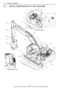
This is the Hitachi workshop manual for the ZX670LC-5G, ZX670LCH-5G and ZX670LCR-5G hydraulic excavators. Published in October 2012 under document number WJBF-EN-00, it is written for the experienced technician and delivers the technical information needed to maintain and repair the machine at component level. Everything from cab removal down to swing bearing ball replacement, from control valve spool disassembly to track adjuster spring compression, is documented with dimensions, torque figures, maintenance standards and step-by-step procedures.
The engine content covers the Isuzu 6WG1 direct-injection, water-cooled, in-line six-cylinder diesel used in these machines, with full mechanical, cooling, fuel, lubrication, charging and induction chapters. All measurements are given in SI units with conversions shown where relevant.
File Details
- Manual type: Workshop Manual (removal and installation, disassembly and assembly)
- Brand: Hitachi
- Models covered: ZX670LC-5G, ZX670LCH-5G, ZX670LCR-5G
- Document number: WJBF-EN-00
- Publication date: October 2012
- Language: English
- File format: PDF
- Page count: 1,012 pages
Chapters Covered
The Hitachi ZX670LC-5G / ZX670LCH-5G / ZX670LCR-5G workshop manual is arranged in six numbered sections, each split into groups with consecutive page numbering so a procedure can be referenced back to the exact group it belongs to.
- Section 1 — General Information: Precautions for Disassembling and Assembling; Tightening Torque (bolts and nuts, piping joints); Painting; Bleeding Air (hydraulic oil tank, hydraulic system, fuel system, radiator); Pressure Release Procedure; Preparation
- Section 2 — Maintenance Standard: Upperstructure (main pump, fan pump, swing motor); Undercarriage (travel device, sprocket, center joint, front idler, upper and lower rollers, track); Front Attachment (pin and bushing, side cutter, point, arm and bucket connection, arm and boom connection, cylinder)
- Section 3 — Upperstructure: Cab; Counterweight; Main Frame; Engine; Radiator Assembly; Hydraulic Oil Tank; Fuel Tank; Pump Device; Control Valve; Swing Device; Pilot Valve; Solenoid Valve; Signal Control Valve; Shockless Valve; Fan Valve; Fan Motor
- Section 4 — Undercarriage: Swing Bearing; Travel Device; Center Joint; Track Adjuster; Front Idler; Upper and Lower Roller; Track
- Section 5 — Front Attachment: Front Attachment (bucket, arm, boom, bushing); Cylinder (boom, arm, bucket)
- Section 6 — Engine: General Information; Service Information; Engine Mechanical; Engine Cooling; Engine Fuel; Starting and Charging; Engine Lubrication; Engine Induction
Altogether the document gives a technician the complete service picture for the ZX670LC-5G class machine: how to safely lift and support major assemblies, how much torque each fastener group takes, which parts must be replaced rather than reused, how to bleed air from the hydraulic and fuel circuits after opening them up, and how to measure wear against the maintenance standards so a rebuild decision is based on the published limit rather than guesswork.
Maintenance Standards and Tolerances
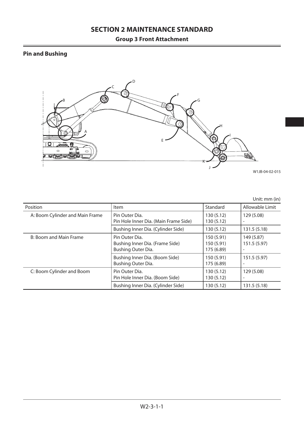
Section 2 is where the numbers live. Every wear surface that matters is listed with a standard value and an allowable limit — plunger-to-cylinder block clearance, shaft outside diameter, shoe thickness, servo piston clearances, sprocket dimensions, idler and roller diameters, track link pitch, bushing and pin dimensions, cylinder rod bend and runout, and the standard dimensions for arm-to-bucket and arm-to-boom pin connections. When a measurement crosses the limit, the manual states whether the correct remedy is cladding and refinishing, repair, or replacement.
Removal, Disassembly and Reassembly Procedures
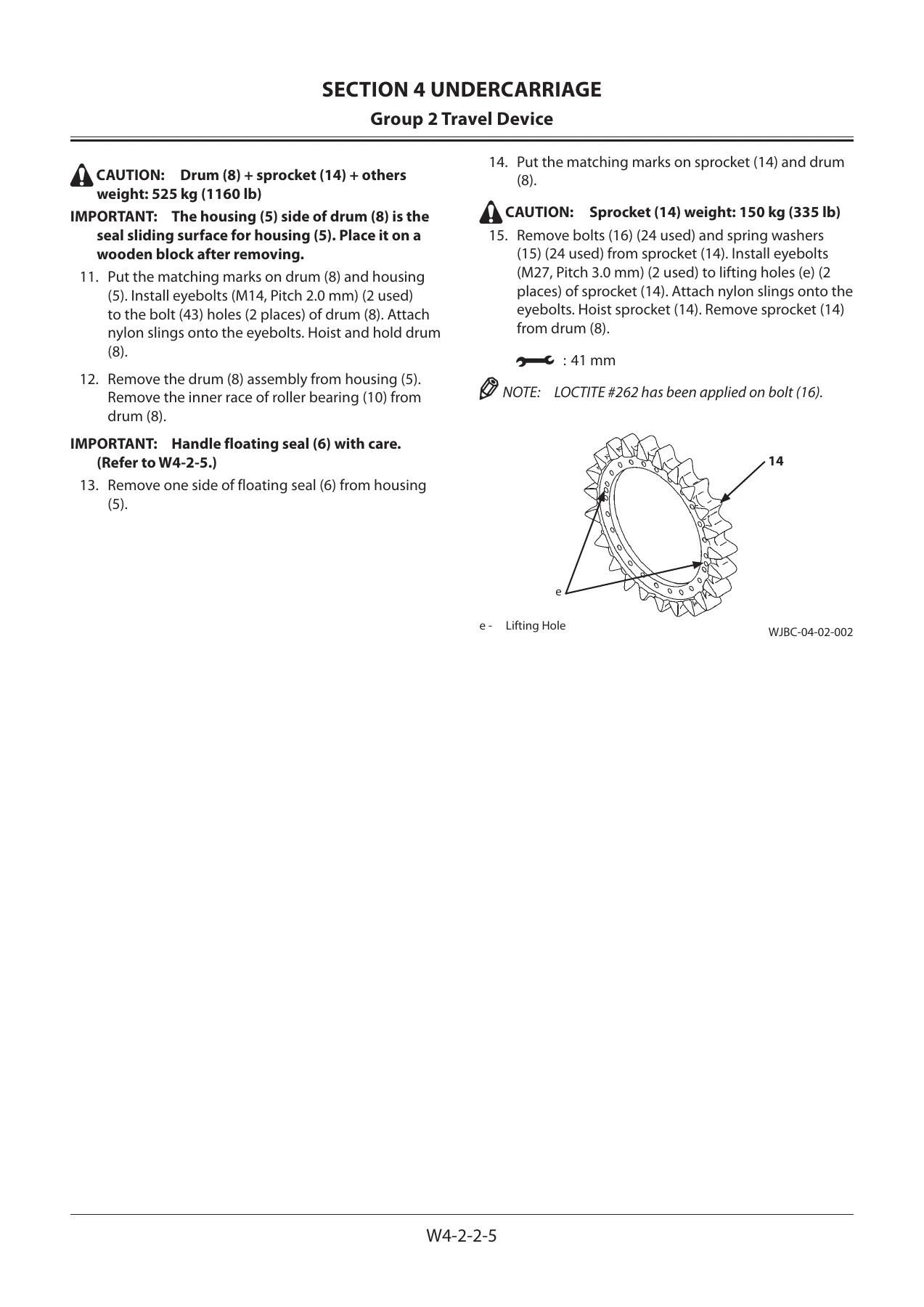
Sections 3, 4, 5 and 6 form the working heart of the Hitachi ZX670LCR-5G workshop manual. Each assembly is presented with a removal sequence, disassembly steps with torque wrench sizes marked, inspection points, then assembly and installation in reverse. Components documented in detail include the pump transmission and main pump regulator, the 4-spool and 5-spool control valve sides, the swing motor and swing reduction gear, the pilot valves (right, left and travel), the solenoid valve units, the signal control valve, the fan valve and fan motor, the travel device and travel motor, the center joint, the track adjuster, the front idler, the upper and lower rollers, and the complete track assembly with master pin removal and installation using the special tool set.
Front Attachment and Cylinders
The front attachment section covers bucket, arm and boom removal and installation with shim and clearance values, plus bushing replacement using the correct installation plate for each joint. The cylinder group walks through boom, arm and bucket cylinder disassembly and reassembly — cylinder head, piston, nut torque values, seal ring and slide ring installation, cushion seal and cushion bearing orientation, and set screw crimping.
Isuzu 6WG1 Engine Service
Section 6 is a full engine manual for the Isuzu 6WG1 six-cylinder diesel, covering the cylinder head, camshaft, rocker arm and shaft assembly, timing gears, flywheel housing, oil pan, piston and connecting rod, crankshaft, crank pulley, flywheel and cylinder block. The cooling, fuel, lubrication and induction chapters include the water pump, thermostat, fuel filter, injection nozzle holders (including the two-stage injection type opening pressure and pre-lift adjustment), injection pump calibration data and governor performance, alternator, starter motor and turbocharger service.
How This Manual Helps You
Working on a 67-tonne hydraulic excavator without the correct figures is expensive. A control valve assembled to the wrong torque leaks. A cylinder nut tightened without the molybdenum disulfide grease specified here will not hold its preload. A swing bearing ball set installed without matching the soft zone marking will shorten bearing life. The Hitachi ZX670LC-5G / ZX670LCH-5G / ZX670LCR-5G workshop manual removes that risk by putting the manufacturer’s own disassembly order, torque values, tightening sequences, sealant call-outs, special tool numbers and inspection limits in front of you before you pick up a wrench.
Whether you are resealing a travel motor, replacing a track adjuster spring, rebuilding a main pump regulator, or chasing an engine fault on the Isuzu 6WG1, this manual supports the job with the procedure and the numbers that go with it. It is written for the experienced technician — the level of detail assumes you know how to use a press, a puller and a torque wrench, but it does not assume you already know this machine.
Instant PDF Delivery
The manual is delivered as an instant-download PDF as soon as payment is confirmed. There is no shipping, no waiting and no physical media. Open it on a laptop in the workshop, on a tablet next to the machine, or on a phone for a quick torque check — and print the pages you need for the job in front of you without worrying about damaging the original.
Reviews
There are no reviews yet.