
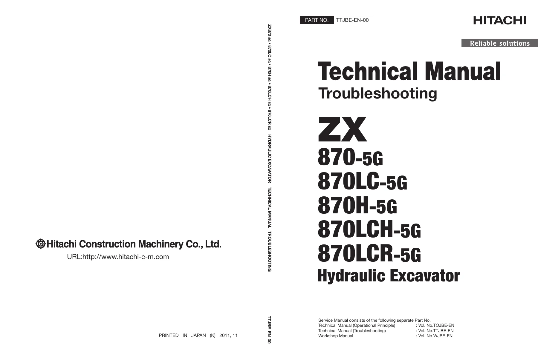
Hitachi ZX870-5G ZX870LC-5G ZX870H-5G ZX870LCH-5G ZX870LCR-5G Excavator Troubleshooting Technical Manual TTJBE-EN-00
Original price was: $39.95.$24.95Current price is: $24.95.
Complete Troubleshooting Technical Manual for Hitachi ZX870-5G, ZX870LC-5G, ZX870H-5G, ZX870LCH-5G and ZX870LCR-5G hydraulic excavators. Covers operational performance testing, fault-code diagnostics, MPDr monitor values, hydraulic and electrical troubleshooting, and air conditioner diagnosis. Instant PDF download.
Description
Hitachi ZX870-5G / 870LC-5G / 870H-5G / 870LCH-5G / 870LCR-5G Troubleshooting Technical Manual
This is the full Troubleshooting Technical Manual (publication number TTJBE-EN-00) for the Hitachi ZX870-5G, ZX870LC-5G, ZX870H-5G, ZX870LCH-5G and ZX870LCR-5G hydraulic excavators. It is the diagnostic counterpart to the workshop manual: where the workshop manual shows how to remove, disassemble and rebuild components, this volume shows how to measure the machine, read its fault codes, interpret live controller data and track a fault down to the correct sensor, harness, solenoid or hydraulic valve.
The document is built around two large sections. Section 4 (Operational Performance Test) gives you the standard values, test conditions and measurement procedures needed to quantify machine condition. Section 5 (Troubleshooting) is the diagnostic core, split into a fault-code driven workflow (Troubleshooting A) and a symptom-driven workflow (Troubleshooting B), with a separate group for the air conditioning system. Everything is written for an experienced technician working with MPDr. or the monitor’s built-in service menu.
File Details
- Manual type: Troubleshooting Technical Manual (T/M Troubleshooting)
- Brand: Hitachi
- Models covered: ZX870-5G, ZX870LC-5G, ZX870H-5G, ZX870LCH-5G, ZX870LCR-5G
- Publication number: TTJBE-EN-00
- Language: English
- File format: PDF
- Page count: 490 pages
Chapters Covered
The contents of this troubleshooting manual are organised as follows.
- Safety
- Recognise safety information, signal words, safe operating and servicing practice
- Fire, fluid, battery, high-pressure and welding precautions
- Section 4 – Operational Performance Test
- Group 1 Introduction – purpose and kinds of performance tests, precautions, test area
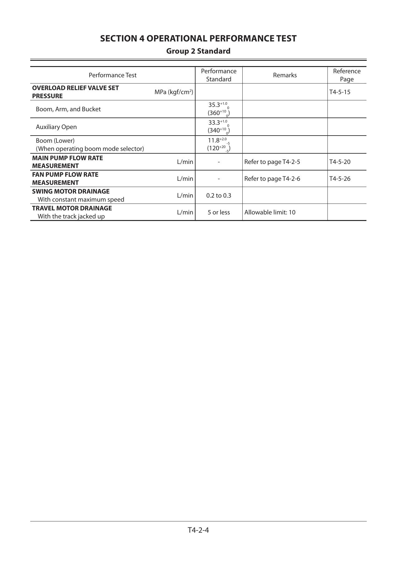
- Group 2 Standard – operational performance standard tables, main pump P-Q diagram, fan pump P-Q diagram, fan pump I-Q diagram, MPDr. monitor indicating values (MC and ECF), sensor activating ranges
- Group 3 Engine Test – engine speed, compression pressure, valve clearance, nozzle, injection timing, lubricant consumption
- Group 4 Machine Performance Test – travel speed, mistrack check, travel motor leakage, swing speed, swing function drift, swing motor leakage, maximum swingable slant angle, swing bearing play, hydraulic cylinder cycle time, dig function drift, control lever operating force, control lever stroke, boom raise / swing combined operation
- Group 5 Component Test – primary and secondary pilot pressure, 4-spool and 2-spool solenoid valve set pressure, main pump and fan pump delivery pressure, main relief and overload relief set pressure, main pump and fan pump flow rate measurement, swing and travel motor drainage
- Group 6 Adjustment – pump learning, engine speed adjustment and engine learning, governor lever and fuel cut lever positions
- Section 5 – Troubleshooting
- Group 1 Diagnosing Procedure – diagnosis workflow, electric system inspection, connector handling, fuse and fusible link inspection, battery voltage check, alternator check, continuity checks, voltage and current measurement, false-signal checking, test harnesses
- Group 2 Monitor – service menu operating procedures (built-in diagnosing system), troubleshooting display, monitoring items, controller version, issued warning record, operation hour meters, communication terminal status, machine setting and attachment constants, monitor setting
- Group 3 e-Service – operation data, daily report data, frequency distribution data, total operating hours, snapshot data, communication system
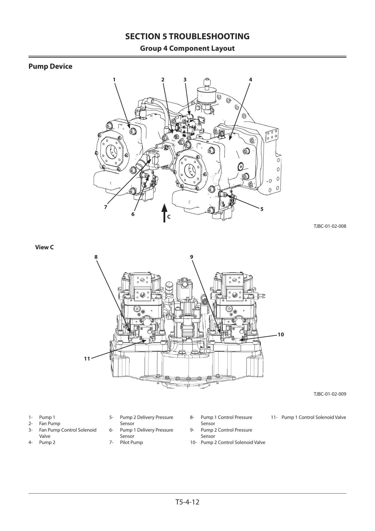
- Group 4 Component Layout – main component, view A, electrical system layout (overview, rear tray, switch panel, cab behind side, isolation switch), horn, oil cooler, auto lubricating system, boom upper side, engine, pump device, control valve, check valve / accumulator, signal control valve, 4-spool and 2-spool solenoid valve units, pilot port charts
- Group 5 Troubleshooting A – fault-code driven diagnosis: MC fault code list, ECF fault code list, monitor controller fault code lists, air conditioner controller fault code list, communication terminal fault code list, plus individual diagnosis procedures for each MC and ECF fault code including CAN0 and CAN1 harness checks
- Group 6 Troubleshooting B – symptom-driven diagnosis: relationship between machine trouble symptoms and related parts, correlation between trouble symptoms and part failures, engine system, all-actuator system, front attachment system, swing system, travel system, other systems, exchange inspection method, emergency boom lowering procedure
- Group 7 Air Conditioner – air conditioner outline and main part functions, controller fault code list and individual fault codes, fault trees for cooling and heating faults, blower motor and compressor clutch checks, manifold gauge diagnostics, compressor oil refill, refrigerant charging, hose and pipe tightening torque
Between them, these groups let a technician move from a customer complaint to a specific measurement. Fault codes are documented with their trigger voltages or currents, their symptoms in machine operation, and the harness and component checks needed to isolate the cause. Where a code could originate from several places, the manual directs you to the sensor, the harness section or the controller as the likely culprit, and where a symptom has no code attached, the troubleshooting tables cross-reference the parts that can produce it.
Diagnostics Built Around Real Machine Data
The performance test side of this manual is what separates a guess from a diagnosis. Every test lists its hydraulic oil temperature, engine control dial position, power mode, work mode and auto-idle switch state, so measurements taken at different times are comparable. Standard values are given for engine speeds in slow idle, fast idle, PWR, ECO and auto-idle, for travel speed, track revolution speed, mistrack allowance, swing speed, swing drift, cylinder cycle times, lever operating force and lever stroke. Component tests give the expected pressures at the pilot filter, the signal control valve, the main relief and overload relief valves, and the expected pump flow rates on the P-Q and I-Q curves.
Controller-side diagnostics are covered in matching depth. The MPDr. monitor value tables list the reference values a healthy machine should show for requested and actual engine speed, engine speed deviation, EC dial voltage, pump delivery pressures, pump regulator pressures, all pilot pressures, travel motor control pressure, boom mode control pressure and the various proportional solenoid valve currents. Sensor activating ranges tell you what a correctly functioning engine control dial, pilot pressure sensor, pump regulator pressure sensor and pump delivery pressure sensor should output, so a sensor can be judged against the manual rather than against a hunch.
Troubleshooting A – Fault Code Diagnostics
Troubleshooting A is used whenever MPDr. or the monitor’s service menu reports a fault code. It covers controller hardware failures (EEPROM, RAM, A/D converter, abnormal sensor voltage), CAN data reception failures between MC, ECF and the monitor controllers, engine control dial circuit faults, pump delivery and control pressure sensor circuits, swing, boom raise, arm roll-in, arm roll-out, bucket roll-in, bucket roll-out, travel, boom lower and attachment pilot pressure sensor circuits, pump control solenoid valve feedback faults, 4-spool and 2-spool solenoid valve feedback faults, hydraulic oil temperature sensor circuits and pump learning failures.
Each entry lists the fault code, the trouble it represents, the inspection method, the evaluation criteria and the resulting cause, with the symptom the operator would actually notice in machine operation. Where sensors share characteristics, the manual notes that the switch-check method can be used to separate a faulty sensor from a faulty harness.
Troubleshooting B – Symptom-Based Diagnosis
Troubleshooting B takes the opposite approach and starts from what the machine is doing wrong. It opens with tables linking machine trouble symptoms to the parts that can cause them, then splits into engine system, all-actuator system, front attachment system, swing system, travel system and other system troubleshooting.
Typical subject areas include a starter that will not rotate, an engine that will not start even when the starter turns, an engine that stalls at full dial or during auto-idle, an engine speed that will not change with the dial, an engine that will not stop on the key switch, ECO mode and HP mode faults, travel HP mode faults, auto-idle faults, stalls under high-altitude conditions and hard starting at low temperature. Actuator-side topics cover all actuators not working, all speeds being slow, travel or bucket single-operation slowness, an actuator that will not stop at neutral, slow fan speed control, weak front attachment power, power digging that does not increase power, individual cylinders not operating, boom mode selector faults, combined-operation slowness between swing and boom raise or arm roll-out, arm and boom anti-drift valve symptoms, abnormal drift, mistracking during combined travel and front attachment operation, and fast travel mode selection faults. Light, wiper, washer and auto-lubrication faults are handled in the other systems group, and the section ends with the exchange inspection method and the emergency boom lowering procedure for when the engine cannot be restarted.
Air Conditioning Diagnostics
Group 7 handles the air conditioning system on its own. It explains how the air conditioning circuit is laid out, what each main part does — the controller, power transistor, blower motor relay, compressor relay, frost sensor, high/low pressure switch, air circulation sensor, fresh air sensor, solar radiation sensor, and the fresh/re-circulated air, air mix and air vent damper servo motors — and then gives the controller fault code list with the voltage or resistance range that triggers each code.
Beyond codes, the group provides structured fault trees for cooling faults and heating faults, procedures for checking a blower motor that does not operate and a compressor clutch that does not engage, manifold gauge diagnosis of the refrigeration circuit, guidance on compressor oil refill quantities for each replaced component, a full refrigerant charging procedure with purging, warm-up and leak inspection steps, and the tightening torques for hose and pipe joints.
What This Manual Lets You Do
With the Hitachi ZX870-5G / ZX870LC-5G / ZX870H-5G / ZX870LCH-5G / ZX870LCR-5G troubleshooting technical manual on hand, you can run a full operational performance test on the machine and compare the results against the standard values instead of judging condition by feel. You can connect MPDr. or open the monitor service menu and read the same reference values the manual uses, so controller data can be checked item by item. You can pull a fault code from MC, ECF, the monitor controller, the air conditioner controller or the communication terminal and follow the documented harness and component checks to the actual failure. When no code is stored, you can work the symptom tables to the parts that can produce that behaviour, whether the complaint is a slow actuator, a mistracking machine, a stalling engine or an air conditioner that will not cool.
Getting the diagnosis right matters on a machine this size. A wrongly replaced pump regulator, control valve spool or pressure sensor is expensive, and a hydraulic system fault left unresolved can damage the pump, the cylinders or the front attachment. The performance test standards and the fault code thresholds in this manual exist so a component is replaced because it failed a measurement, not because it seemed the likely suspect. The pump learning and engine learning procedures, the relief valve set pressure adjustments and the sensor activating ranges all depend on following the documented values and conditions, and that is exactly what this volume provides.
IMAGES PREVIEW
Instant PDF Delivery
This is a digital PDF manual. It is available for immediate download as soon as payment is completed — no shipping, no waiting for a physical book, and no customs. The file can be opened on a laptop, tablet or smartphone, searched on screen while you are at the machine, and printed page by page if you prefer a paper copy in the workshop. Keep it on your service computer or load it onto a tablet and carry the entire diagnostic reference with you to the job site.
Reviews
There are no reviews yet.