
Honda CRF1000A/A2/AL/AL2/D/D2/DL/DL2-J Shop Manual Addendum 62MJP00Y – PDF
Original price was: $54.95.$34.95Current price is: $34.95.
Honda CRF1000A/A2/AL/AL2/D/D2/DL/DL2-J Shop Manual Addendum covering 2017 publication updates for service specifications, torque values, maintenance, PGM-FI and DCT diagnostics, ABS, electrical systems, body components, engine removal/installation and complete model-specific wiring diagrams. Book number 62MJP00Y, 228-page PDF.
Description
Honda CRF1000A/A2/AL/AL2/D/D2/DL/DL2-J Shop Manual Addendum
This 228-page Honda shop manual addendum contains service and repair information for CRF1000A, CRF1000A2, CRF1000AL, CRF1000AL2, CRF1000D, CRF1000D2, CRF1000DL and CRF1000DL2-J models. Issued in November 2017 as book number 62MJP00Y, it brings together model-specific specifications, routing information, maintenance data, component removal and installation procedures, diagnostic trouble-code charts, electrical testing sequences and wiring diagrams.
This is an addendum rather than a replacement for every earlier CRF1000 service section. The introduction specifically directs technicians to CRF1000/A/D-G, H Shop Manual No. 62MJP00 and CRF1000/A/D-H, J Shop Manual No. 62MJP01Z for service procedures and data not included here. For the systems revised or expanded in this J-model addendum, however, the manual supplies substantial diagnostic and repair detail.
File Details
- Manual type: Shop Manual Addendum
- Brand: Honda
- Models: CRF1000A/A2/AL/AL2/D/D2/DL/DL2-J
- Book number: 62MJP00Y
- Date of issue: November 2017
- Language: English
- Pages: 228
- File format: PDF
Service Data and Model Differences
The opening service-data section is unusually useful because it separates specifications by CRF1000 variant where the machines differ. It covers overall dimensions, wheelbase, seat and footpeg height, ground clearance, curb weight and maximum load, followed by frame, suspension, tire, brake and fuel-tank specifications. Engine data includes cylinder arrangement, bore and stroke, displacement, compression ratio, valve timing, lubrication and cooling information. The manual also distinguishes the conventional manual-transmission CRF1000A/A2/AL/AL2 drivetrain from the DCT-equipped CRF1000D/D2/DL/DL2 versions, including transmission, reduction and gear-ratio information.
Dedicated specification tables provide fuel pressure and pump flow, coolant capacities and thermostat values, front and rear suspension standards and service limits, drive-chain data, battery and alternator figures, lighting and fuse information, sensor resistance values and extensive torque settings. Lubrication and seal-point charts identify the specified grease, fluid or sealing material and its application location.
Chapters Covered
- SPECIFICATIONS
- TORQUE VALUES
- LUBRICATION & SEAL POINTS
- CABLE & HARNESS ROUTING
- TECHNICAL FEATURE
- BODY PANEL LOCATIONS
- MAINTENANCE SCHEDULE
- PGM-FI SYSTEM
- GRIP APS/RIGHT HANDLEBAR SWITCH
- IGNITION SYSTEM
- ELECTRIC STARTER SYSTEM
- DCT SYSTEM
- ENGINE REMOVAL / INSTALLATION
- ABS SYSTEM
- BATTERY/CHARGING SYSTEM
- COMBINATION METER
- IMMOBILIZER SYSTEM (HISS)
- WIRING DIAGRAM
Specifications, Torque Values and Lubrication
The specifications and service-data pages establish the measurements and limits needed before adjustment or replacement decisions are made. Torque tables cover body and exhaust fasteners, maintenance items, engine removal and installation, electrical components and other assemblies. The lubrication section maps grease, brake fluid, fork fluid, chain lubricant and sealant applications to individual pivots, seals, bearings and mating surfaces.
Cable & Harness Routing
A long sequence of illustrated routing pages shows the position of brake hoses, handlebar-switch wiring, grip-heater wiring, clutch or parking-brake cables, wheel-speed sensor wiring, ignition wiring, fuel and breather hoses, ECM/PCM connectors, charging-system wiring and rear harness components. Connector colors, routing directions, clamp locations and selected dimensional references are shown directly on the illustrations, making this section valuable after major disassembly or electrical repairs.
Technical Feature and Body Components
The technical-feature section explains the ESS Emergency Stop Signal system and how the ABS modulator, speed signals, brake signals and turn-signal circuit interact. Body-panel location and removal charts identify the order for accessing covers, cowlings, skid plate, rear carrier and related bodywork. Separate procedures then cover windscreen, middle cowl, front cover, inner panel covers, skid plate, front side pipe, seat catch stay, ETC tray, side covers, rear inner body sections, rear carrier, carrier bracket, rear cowl and fender assemblies.
Maintenance, Exhaust and Chassis Work
Maintenance schedules identify inspection, replacement, cleaning and lubrication intervals for fuel and throttle systems, air cleaner, spark plugs, valve clearance, engine oil and filters, coolant, drive chain, brakes, suspension, steering and related items. Additional illustrated procedures cover throttle operation, spark-plug access, muffler and exhaust-pipe work, sidestand service and other chassis-related operations with installation notes and torque values where specified.
PGM-FI Diagnostics and Throttle-By-Wire
The PGM-FI section includes component locations, system diagrams, a detailed DTC index and step-by-step fault tracing. Diagnostic routines cover MAP, ECT, IAT and vehicle-speed sensors; fuel injectors; O2 sensor and heater circuits; gear-position and bank-angle sensors; wheel-speed signals; throttle-position sensors; accelerator-position sensors; TBW motor and relay faults; EVAP and PAIR solenoids; ignition-coil circuits; CAN communication and related circuits. Procedures specify connector terminals, wire colors, voltage or resistance checks, continuity tests and decision points for locating opens, shorts, faulty sensors or control-unit problems.
Grip APS, Ignition and Starting Systems
The Honda CRF1000 shop manual addendum provides APS inspection data and illustrated right-handlebar switch/APS removal and installation procedures, including harness routing and throttle-grip installation. The ignition section contains its own system diagram, CKP sensor and ignition-coil inspection information, while the electric starter coverage provides the system information needed for starting-circuit work.
DCT System Diagnostics
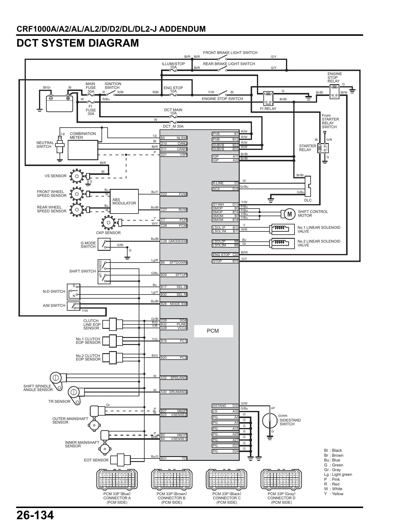
For CRF1000D/D2/DL/DL2 variants, the DCT material is one of the largest technical areas in the addendum. It includes a DCT system diagram, DTC index and extensive DTC troubleshooting, with checks involving sensors, solenoids, clutch-related circuits, shift controls and PCM connections. The manual also includes A/M switch troubleshooting and notes the required clutch initialize learning procedure when the PCM is replaced.
Engine, Swingarm and Brake Service
Later service sections provide engine removal and installation information for applicable DCT variants, followed by swingarm and front brake-caliper material. These procedures are supported by the earlier torque, lubrication, routing and service-data sections, allowing the technician to cross-reference installation values rather than relying on memory during reassembly.
ABS, Charging and Electrical Systems
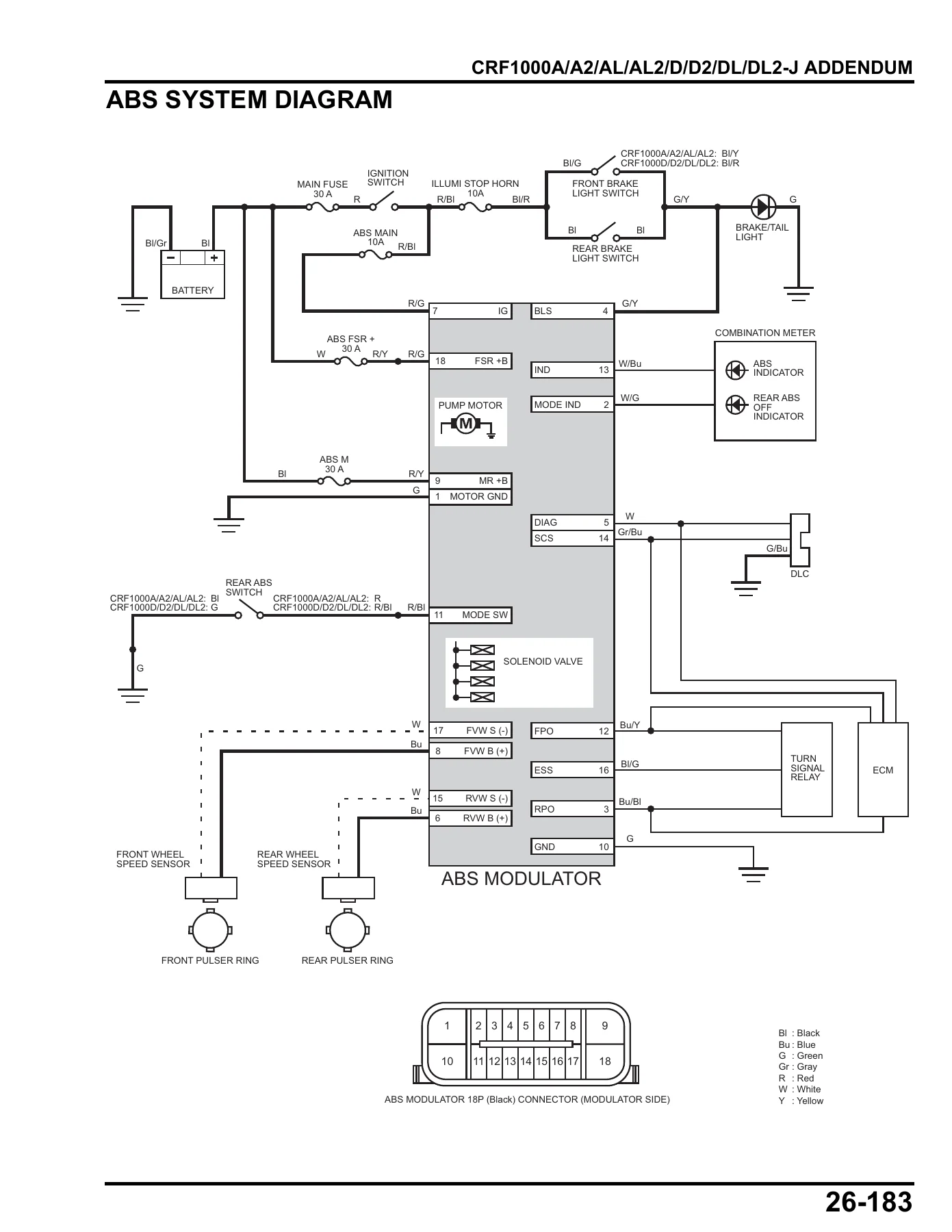
The ABS portion supplies a system diagram, DTC index and guided troubleshooting for wheel-speed sensor circuits, pulser rings, power circuits, modulator faults and other ABS conditions. Diagnosis includes clearance and condition checks, continuity and voltage tests, DTC clearing and confirmation by test riding where directed. Battery and charging sections include battery specifications, battery testing, charging-system troubleshooting and inspection information.
Combination Meter, HISS and Wiring Diagrams
Electrical coverage continues through turn signals, combination meter, gear-position or neutral switching, shift spindle switch, grip heater and the HISS immobilizer system. HISS material includes the system diagram and troubleshooting for the ECM/PCM and immobilizer receiver. The manual closes with full wiring diagrams separately identified for CRF1000A/A2/AL/AL2 and CRF1000D/D2/DL/DL2, giving technicians a broad circuit reference for tracing electrical faults and checking connections across the motorcycle.
A Focused Repair Reference for CRF1000 J-Model Service
For anyone servicing the CRF1000A/A2/AL/AL2/D/D2/DL/DL2-J variants, this Honda CRF1000 shop manual addendum puts the J-model changes and system-specific procedures in one technical reference. It is particularly valuable when diagnosing PGM-FI, throttle-by-wire, DCT, ABS, charging, HISS or wiring faults, or when dismantling bodywork and routing cables, hoses and harnesses correctly during reassembly.
Correct specifications, test values, connector identification, tightening torques and illustrated assembly details matter when a repair moves beyond basic maintenance. This 62MJP00Y PDF gives you immediate access to that information after purchase, with no book to ship or wait for. Open it on a computer, tablet or phone, keep it available in the workshop, and print the pages you need for the job.
IMAGES PREVIEW
Reviews
There are no reviews yet.