
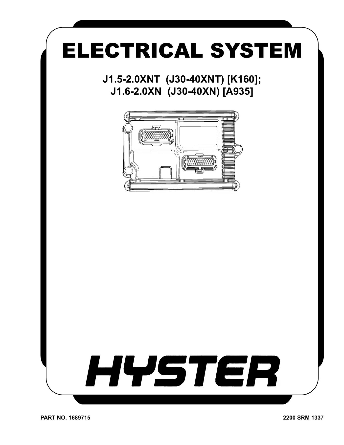
Hyster J1.5-2.0XNT and J1.6-2.0XN Electrical System Service Manual 2200 SRM 1337
Original price was: $34.95.$21.95Current price is: $21.95.
Complete electrical system service manual for Hyster J1.5-2.0XNT (J30-40XNT) (K160) and J1.6-2.0XN (J30-40XN) (A935) electric lift trucks. Covers display panels, hydraulic controls, sensors, switches, motor controllers, VSM, fuses, and lights with step-by-step removal and installation procedures.
Description
Hyster J1.5-2.0XNT and J1.6-2.0XN Electrical System Service Manual
This is the electrical system service manual for Hyster J1.5-2.0XNT (J30-40XNT) (K160) and J1.6-2.0XN (J30-40XN) (A935) electric lift trucks, published as document 2200 SRM 1337. It walks a technician through the removal, replacement, testing, and adjustment of the electrical components that make these trucks run, from the display panel and key or keyless switch down to the motor controllers and the Vehicle Systems Manager.
Because these are electric trucks, the electrical system is not a side chapter — it is the machine. That is why this manual spends its pages on real component-level work: how to discharge the capacitors safely before opening anything, how to swap a mini-lever, how to test full stroke and neutral return on an E-Hydraulic control, and how to replace a steering axle sensor that sits underneath the hydraulic pump and motor assembly.
File Details
- Manual type: Electrical System Service Manual (SRM)
- Brand: Hyster
- Models covered: J1.5-2.0XNT (J30-40XNT) (K160); J1.6-2.0XN (J30-40XN) (A935)
- Document number: 2200 SRM 1337
- Language: English
- Page count: 118 pages
- File format: PDF
Chapters Covered
- Safety Precautions, Maintenance and Repair — lifting, blocking, battery disconnect, approved parts, welding warnings
- Discharging the Capacitors — required procedure before any electrical repair
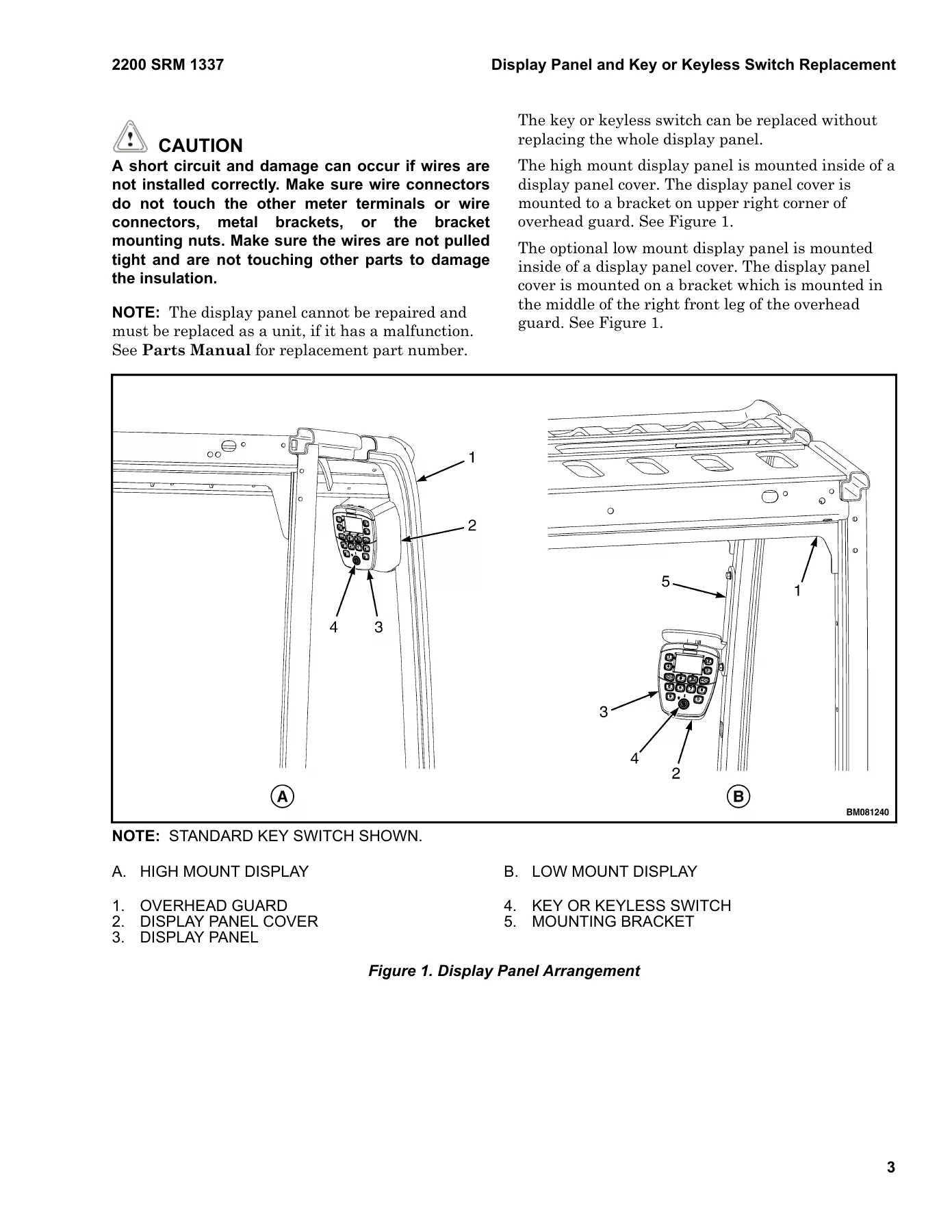
- Display Panel and Key or Keyless Switch Replacement — display panel remove/install, key or keyless switch removal, warning buzzer
- Electronic and Manual Hydraulic Controls
- General
- Manual Hydraulic Controls — upper front cover, direction control switch, clamp button, Return To Set Tilt (RTST) button, emergency disconnect switch
- E-Hydraulic Controls Test — mini-levers, full stroke test, function returns to neutral test, push (override) button
- E-Hydraulic Controls — mini-levers remove and install, armrest assembly, horn button, direction control switch, emergency disconnect switch, push (override) buttons and function selection button
- Electronic-Hydraulic Controls, After January, 2020 — general, test procedures, mini-levers, armrest assembly, horn button, direction control switch, emergency disconnect switch, push (override) buttons
- Sensors and Switches
- Synchronous Steering Valve
- Steering Axle Sensor — coverage split by build date (before and after September 15th, 2011; after November, 2014)
- Hydraulic Motor Speed Sensor
- Hydraulic Motor Temperature Sensor
- Transmission Speed Sensor
- Traction Motor Temperature Sensor
- Tilt Position Sensor
- Low Level Brake Fluid Switch
- Service Brake Pressure Sensor — before and after February, 2016
- Accelerator Pedal Position Sensor
- Seat Belt Sequence Module
- Seat Sensor (Operator Presence System) — non-suspension, full suspension, and swivel seats
- Steering Wheel Position Sensor
- Load Weight Sensor
- Battery Gate Switch — before and after December, 2015
- Horn Switch and Rear Horn Button Switch
- Impact Sensor
- Steering Motor Speed Sensor
- Hydraulic Tank Level Sensor
- Hydraulic Filter Pressure Switch
- Hydraulic Oil Temperature Sensor
- Motor Controllers Replacement
- General
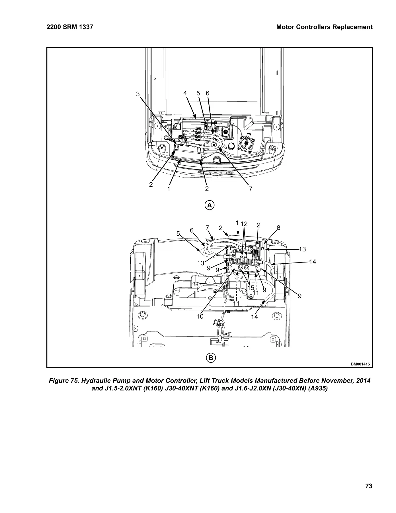
- Hydraulic Pump and Motor Controller — before and after November, 2014
- Fan removal and installation
- Traction Motor Controllers
- Line Contactor — model and build-date variants
- Steering Motor Controller
- Vehicle Systems Manager — remove, install, programming a new VSM and/or display panel, PC Service Tool software
- Fuses — panel arrangement before and after November, 2010, and for J1.5-2.0XNT (K160) after November, 2014
- Audible Alarm
- Battery Connection — inspection, cable replacement
- Cab Heater — reference to Operator’s Cab 0100SRM1446
- Lights — work lights (halogen and LED), strobe light, LED tail/backup/brake lights, front marker/turn signal lights, converter
Across those chapters, the manual provides the practical sequence a technician actually needs: read the warning, lower the mast, discharge the capacitors, disconnect the battery, tag the connectors, and then follow the specific removal and installation steps for the component in front of you. Torque values appear throughout, such as the 13 to 15 N·m (115 to 133 lbf in) figure for motor controller power cables, the 26 N·m (230 lbf in) for hydraulic motor mounting capscrews, and the 2.2 ± 0.2 N·m (19.5 ± 1.8 lbf in) for the emergency disconnect switch nut. The manual also flags which procedures differ by production date, which matters on a truck platform that changed significantly in November 2014, December 2015, February 2016, and January 2020.
What This Manual Lets You Do
The Hyster J1.5-2.0XNT and J1.6-2.0XN Electrical System Service Manual gives you the complete electrical repair path for both truck families. You can replace a failed display panel or keyless switch without pulling the whole panel, remove and install manual hydraulic control handles and their direction control switches, swap a clamp button or Return To Set Tilt button, test and replace E-Hydraulic mini-levers, and service the armrest-mounted switches on trucks built after January 2020.
On the sensor side, the coverage is unusually specific. You get distinct procedures for steering axle sensors on trucks built before September 15th, 2011, after that date, and after November, 2014. There are separate sections for hydraulic motor speed sensors before and after November, 2014, transmission speed sensors, tilt position sensors, brake fluid level switches, brake pressure sensors before and after February, 2016, battery gate switches before and after December, 2015, and the steering motor speed sensor on J1.5-2.0XNT (K160) trucks built after November, 2014.
The motor controller section covers the hydraulic pump and motor controller, both traction motor controllers, the line contactor, and the steering motor controller, with the fan removal and installation steps included. The Vehicle Systems Manager chapter explains removal, installation, and the Application Code and Configuration Data File requirements for programming a new VSM or display panel, plus how to connect the PC Service Tool.
Why Correct Procedures and Specs Matter Here
Electric lift truck electrical work is unforgiving. The capacitors in the transistor controllers can hold a charge after the battery is disconnected, which is why the manual opens with a mandatory discharge procedure. Emergency disconnect switches must not be activated during that discharge or the controllers stay isolated and the capacitors will not drain properly. Motor controller power cables have specific torque values for a reason, and the manual calls out the silicone compound and lubricating grease required at connector terminals. Without those details, a repair can create a new fault instead of fixing the old one.
Production-date changes also matter. The same sensor or switch can be mounted differently, use different hardware, or require a different removal sequence depending on whether the truck was built before or after November 2014, December 2015, or February 2016. This manual separates those cases instead of assuming one procedure fits every truck.
IMAGES PREVIEW
Instant PDF Delivery
The manual is delivered as a PDF download immediately after payment. There is no shipping, no waiting, and no physical book to keep track of in the shop. You can open it on a laptop, tablet, or phone at the truck, print the pages you need for a job, and keep the rest on file. When the next electrical fault comes in, the procedure is already on your device.
Reviews
There are no reviews yet.