
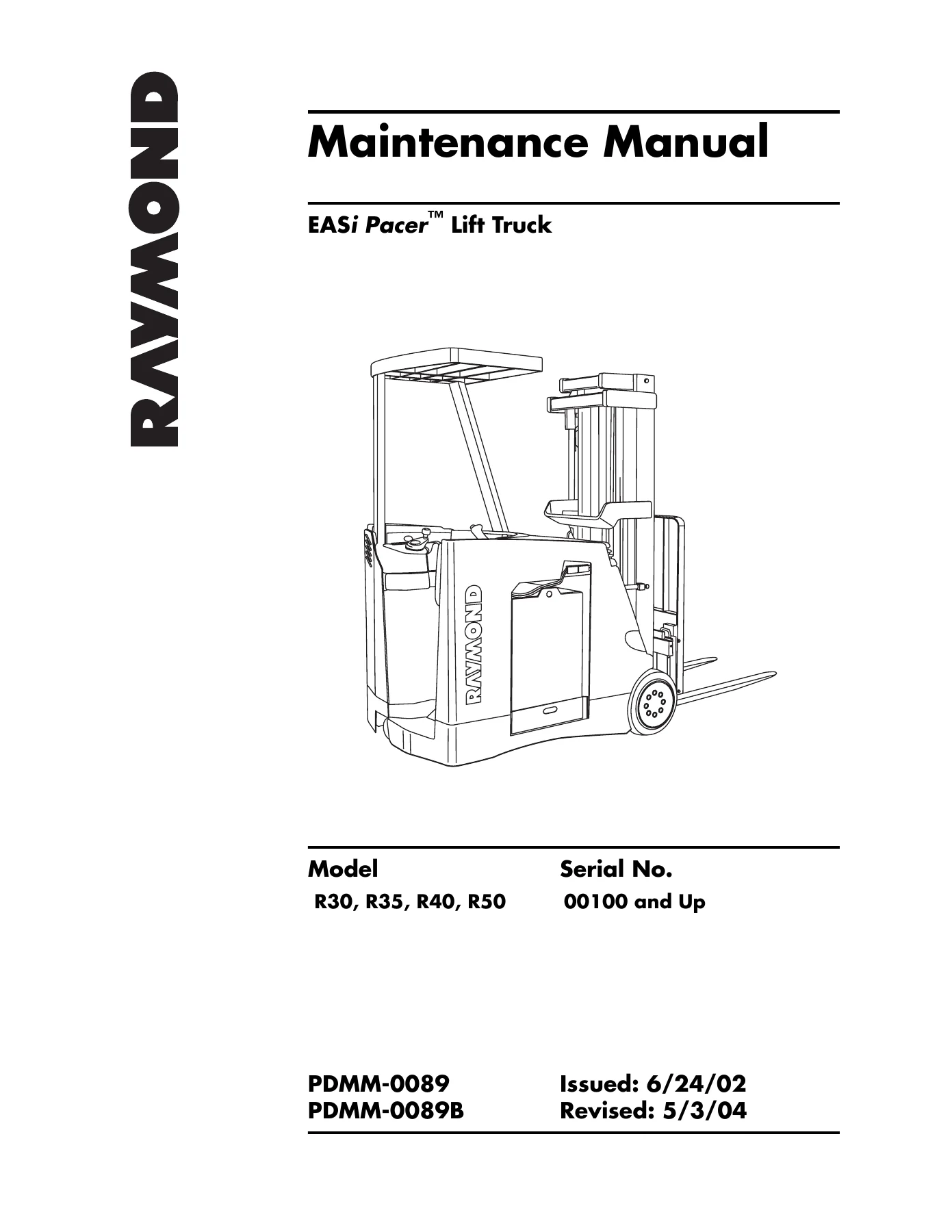
Raymond EASi Pacer R30 R35 R40 R50 Lift Truck Maintenance Manual PDMM-0089B
Original price was: $39.95.$23.95Current price is: $23.95.
Complete Raymond EASi Pacer maintenance manual for R30, R35, R40 and R50 lift trucks, serial 00100 and up. 464 pages covering scheduled service, fault codes, electrical tests, hydraulics, mast and component procedures. Instant PDF download.
Description
Raymond EASi Pacer R30 R35 R40 R50 Maintenance Manual – PDMM-0089B
This is the full Raymond EASi Pacer Lift Truck Maintenance Manual, published by The Raymond Corporation under document number PDMM-0089 and reissued as PDMM-0089B with a revision date of 5/3/04. It applies to the R30, R35, R40 and R50 models from serial number 00100 and up, and it supersedes the earlier EASi Pacer Maintenance Manual PDMM-0068. At 464 pages it is a genuinely complete workshop reference rather than a quick-start leaflet – it walks through scheduled maintenance intervals, fault code diagnosis, analog and digital test routines, component removal and installation, hydraulic theory and full electrical and hydraulic schematics.
File Details
- Manual type: Maintenance / service manual
- Manufacturer: The Raymond Corporation
- Models covered: R30, R35, R40, R50 (EASi Pacer Lift Truck)
- Serial number range: 00100 and Up
- Document numbers: PDMM-0089, PDMM-0089B
- Issued: 6/24/02
- Revised: 5/3/04
- Language: English
- Page count: 464 pages
- File format: PDF
Chapters Covered
- How to Use This Manual – map of the manual, manual design, abbreviations and symbols
- Safety – definitions, general safety, battery safety, static precautions, jacking safety, towing, welding safety
- Systems Overview – lift truck specifications, modes of operation
- Scheduled Maintenance – maintenance guidelines, Maintenance Minder tool, operator’s daily checklist, initial 90 day maintenance, every 180 days or 500 deadman hours, every 360 days or 1500 deadman hours
- Troubleshooting – electrical troubleshooting guidelines, motor overheating, shorts to frame test, CAN Bus troubleshooting, wiring, electrical connector locator chart, hydraulics, symptom tables for hydraulic functions, travel functions and electrical functions
- Messages, Codes and Tests – messages and codes summary list, message and code summary tables, power amplifier LED diagnostics, full fault code descriptions, analog input tests, digital input tests, digital output tests
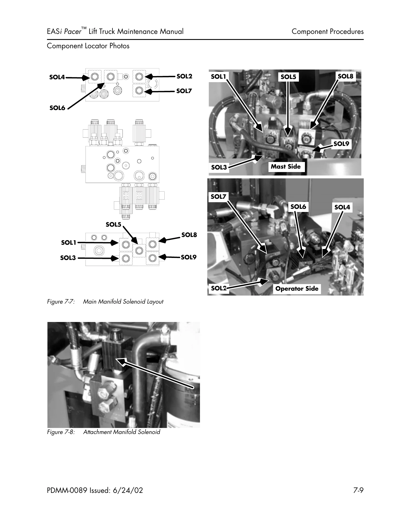
- Component Procedures – component locator photos, steering and controls, steer motor, wheel and tire assemblies, steerable wheel assembly, steer chain adjustment, operator display card, control handle, drive units, axle seal, brake, fuses, contactor fuse panel, contactors, Vehicle Manager, cold storage conditioning, motors, drive motor, lift motor, hydraulic fluid, pressure adjustment, steer pump, lift/aux pump, lift cylinders, flow control valve, quad mast hose replacement, mast components, mast removal and installation, mast disassembly, mast shimming
- Theory of Operation – navigation instructions for the pin-out matrix, pin-out matrix, lift/lower system, auxiliary functions, steering, travel circuit components
- PC Loader Program – installation, connecting a PC to the lift truck, flash memory programming, blank primary memory, factory defaults, options
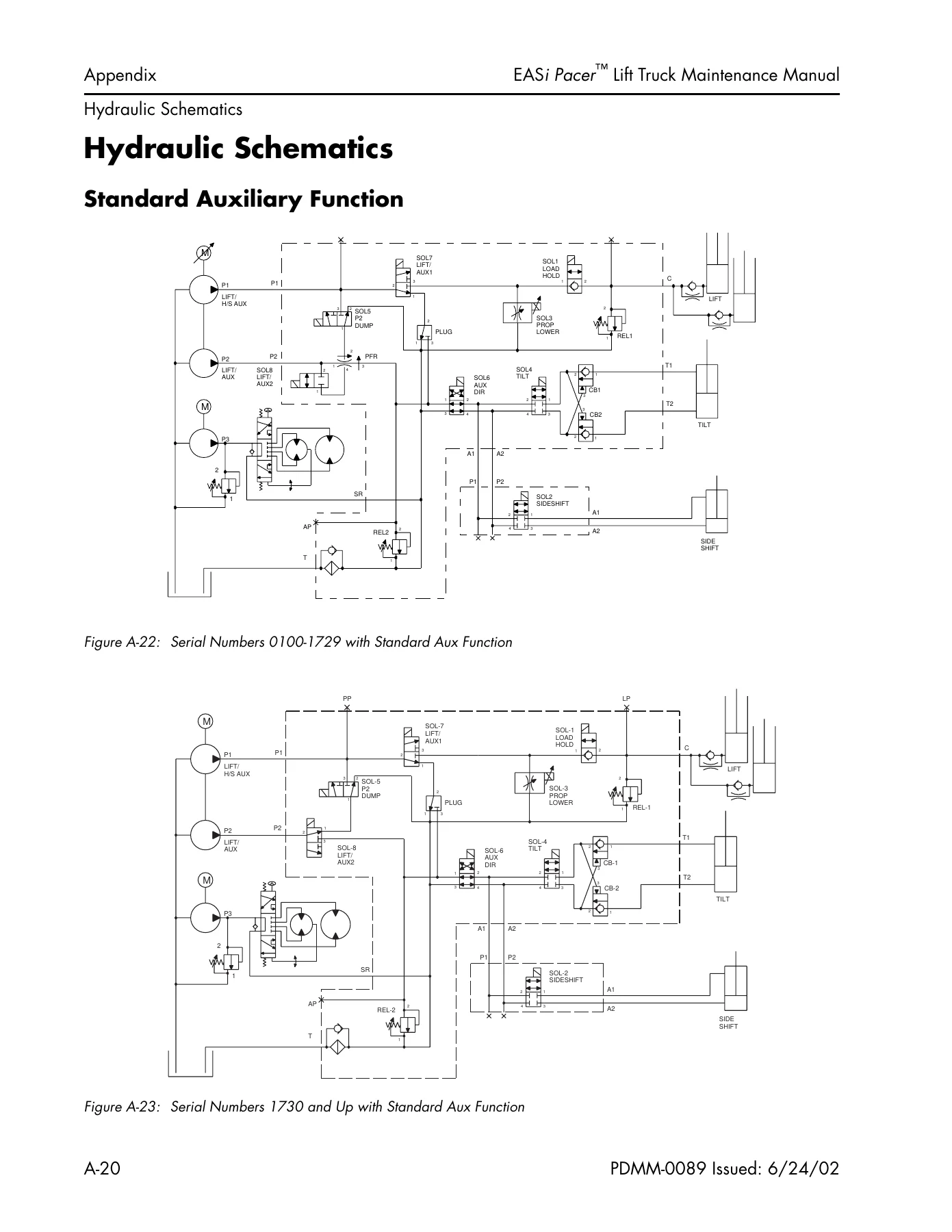
- Appendix – lubrication equivalency chart, thread adhesives, sealants and lubricants, component specific torque information chart, standard, metric and brass torque charts, decimal equivalent chart, standard/metric conversions, electrical schematics, hydraulic schematics, attachment configurations
- Index
Read end to end, this EASi Pacer maintenance manual gives a technician a working picture of the whole truck rather than one isolated system. The early chapters establish the safety boundaries for battery work, static-sensitive electronics, jacking and towing, then the systems overview and specification plate decode the truck’s ratings so service decisions are made against the correct load centre and battery weight. From there the scheduled maintenance tables set out exactly what has to be checked at 90 days, at 180 days or 500 deadman hours, and at 360 days or 1500 deadman hours, with each line pointing to the component procedure that carries out the job. That structure is what separates this document from a generic lift truck book – every inspection item links forward to the procedure, the test, or the torque value that completes it.
Fault Codes, Diagnostic Tests and Electrical Troubleshooting
The troubleshooting and messages chapters are the heart of the manual for anyone chasing an intermittent fault. The Raymond EASi Pacer uses a Vehicle Manager and separate traction and lift power amplifiers communicating over a CAN Bus, and the manual documents the whole diagnostic chain: how to read the power amplifier LED blink patterns, how to interpret each fault code, and which specific test to run next. Codes covered include traction power amplifier overheat, emergency power off detection, battery low, lift power amplifier overheat, armature and field circuit shorts and opens, no-movement-detected conditions, motor overheat, brush wear indicators, LPC, TPC and steer contactor faults, CAN Bus communication failures, pressure sensor faults, lift circuit faults, throttle and lift controller out-of-range readings, software and memory errors, plus the steer position and speed feedback faults.
Behind every code sits a defined test routine. The analog input tests let you read armature current, field current, motor and power amplifier temperatures, battery discharge indicator voltage, throttle potentiometer voltage, lift/lower potentiometer voltage, lift motor current and the +12 VDC supply. The digital input tests step through the deadman switch, EPO switch, high speed limit switch, tilt up and down switches, sideshift switches, lift limit mast switch, steering fuse, brush wear indicators, speed sensors, steer position sensor, battery gate switches, control handle option switches and the horn switch. The digital output tests then cycle the TPC, LPC and STR contactors, the load hold, sideshift, proportional lower, tilt, P2-dump, auxiliary direction, lift/aux 1 and 2, proportional relief, high speed aux 1 and 2 and aux dump solenoids, ramp the three power amplifiers, toggle the traction motor brakes, ramp the display alarm and toggle the horn. Every test lists expected values and a diagnosis and repair sequence, so faults are narrowed to a component rather than guessed at.
Component Procedures, Hydraulics and Theory of Operation
The component procedures chapter is written as step-by-step work instructions grouped by truck system, with torque figures and thread-locking compound part numbers called out as you go. It covers removing and installing the steer motor and steer pump, the drive wheel and tire, the steerable wheel assembly and its bearings and seals, steer chain adjustment, the operator display card, the control handle including the solid state replacement path and control module installation, the drive units with their oil fill and axle seal procedure, the brake assembly with air gap adjustment for both shim and adjustable spacer style brakes, the contactor fuse panel, contactors, the Vehicle Manager, cold storage conditioning, drive and lift motors, hydraulic fluid selection and bleeding, system pressure adjustment, lift cylinders, flow control valve and the complete quad mast hose routing and bracket adjustment.
The theory of operation chapter supplies the pin-out matrix, a connection-level table that identifies what each wire carries, what it should read in a given state, where the signal comes from and where it goes. It then explains signal flow for the lift/lower system with and without the high flow auxiliary option, the auxiliary functions including tilt, sideshift and hi-flow attachments, the steering circuit and the travel circuit components. Separate sections explain proportional plugging, torque on demand, current limiting and thermal cut-back so the behaviour of the truck under load makes sense during diagnosis. This is backed by full electrical schematics, standard and high speed auxiliary hydraulic schematics, and the attachment configuration tables that map sideshift and high speed auxiliary combinations to the correct PC Loader settings.
Who This Manual Is Written For
The Raymond EASi Pacer R30 R35 R40 R50 maintenance manual is aimed at service technicians, fleet maintenance departments and technically minded operators who already understand lift truck systems. It assumes access to normal workshop equipment – a digital multimeter, a clamp-on ammeter, pressure gauge and pressure sensing coupler for hydraulic settings, and basic hand tools – and it references Raymond-specific special tools and part numbers where a job requires them. Because it is a maintenance manual rather than an operator handbook, the emphasis throughout is on inspection intervals, measured values, adjustment limits and fault isolation rather than on how to drive the truck.
IMAGES PREVIEW
Complete Coverage in One Downloadable PDF
With this Raymond EASi Pacer R30 R35 R40 R50 Lift Truck Maintenance Manual PDMM-0089B on hand, a technician can carry out the full scheduled maintenance programme, diagnose and clear fault codes, run the factory analog, digital input and digital output test routines, adjust brake air gaps to the specified 0.008 to 0.018 in., set lift and auxiliary system pressures against a gauge, service the drive units and axle seals, replace and bleed lift cylinders, route and clamp quad mast hoses to the documented torques, and rebuild a mast with correct bearing shimming. Doing that work against the published procedures and torque values is what keeps a reach truck stopping inside its specified distance, keeps motors from overheating through a dragging brake or an over-set relief valve, and keeps the Vehicle Manager from logging the faults that put the truck out of service.
This is a 464 page document, so it is a reference you keep rather than read once – and having it on a laptop, tablet or phone in the workshop means the torque chart, the fault code table, the pin-out matrix and the schematic for the circuit you are actually testing are all a few taps away. The file is delivered as an instant PDF download after checkout, with no shipping and no waiting, and every page can be printed if you prefer a paper copy at the truck. Whether you are maintaining a single R30 or running a mixed fleet of R30, R35, R40 and R50 trucks from serial 00100 upward, this is the service documentation that tells you what to check, what it should measure, and what to do when it does not.
Reviews
There are no reviews yet.