Isuzu 6HK1-TC Engine Commercial Truck Foreword Tiltmaster Service Manual – PDF DOWNLOAD
Original price was: $67.95.$21.95Current price is: $21.95.
Isuzu 6HK1-TC Engine Commercial Truck Foreword Tiltmaster Service Manual
Description
Isuzu 6HK1-TC Engine Commercial Truck Foreword Tiltmaster Service Manual
FILE DETAILS:
Isuzu 6HK1-TC Engine Commercial Truck Foreword Tiltmaster Service Manual
Language : English
Pages : 368
Downloadable : YES
Format : PDF
Size : 25.5 MB
DESCRIPTION:
Isuzu 6HK1-TC Engine Commercial Truck Foreword Tiltmaster Service Manual
FOREWORD:
This service manual contains diagnosis, on-vehicle service, wiring diagrams, and component unit repair for 6HK1-TC engine. (1998 — 2001 FSR. FTR, FVR 8. 2000 -— 2001 FRR (WT5500)/ENGINE). Keep this manual in a handy place for ready reference. if properly used, it will enable the technician to serve the owners of these vehicles.
- This service manual is intended for use by professional, qualified technicians. Attempting repairs or service without the appropriate training, tools, and equipment could cause injury to you or others and damage to your vehicle that may cause it not to operate properly. These vehicle contain parts dimensioned in the metric system as well as in the customary system.
- Some fasteners are metric and are very close in dimension to familiar customary fasteners in the inch system. It is important to note that. during any vehicle maintenance procedures, replacement fasteners must have the same measurements and strength as those removed, whether metric or customary. (Numbers on the heads of metric bolts and on surfaces of metric nuts indicate their strength. Customary bolts use radial lines for this purpose. while most customary nuts do not have strength markings.)
- Mismatched or incorrect fasteners can result in vehicle damage or malfunction, or possibly personal injury. Therefore, fasteners removed from the vehicle should be saved for re-use in the same location whenever possible. Where the fasteners are not satisfactory for re-use, care should be taken to select a replacement that matches the original. For information and assistance, see you Authorized dealer.
TABLE OF CONTENTS:
Isuzu 6HK1-TC Engine Commercial Truck Foreword Tiltmaster Service Manual
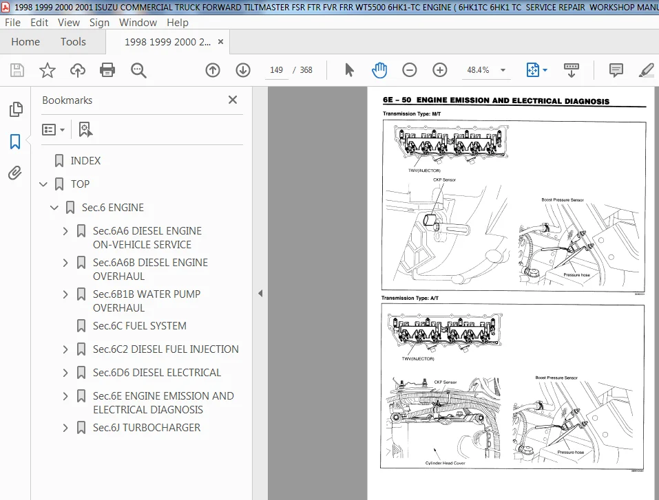
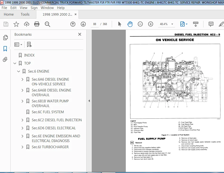
INDEX......................................................................................................................  0
TOP........................................................................................................................  1
	Sec.6 ENGINE...........................................................................................................  5
		Sec.6A6 DIESEL ENGINE ON-VEHICLE SERVICE...........................................................................  6
			GENERAL DESCRIPTION............................................................................................  6
				ENGINE IDENTIFICATION......................................................................................  7
				ENGINE LUBRICATION.........................................................................................  7
			ON-VEHICLE SERVICE.............................................................................................  7
				VALVE ROCKER ARM COVER.....................................................................................  7
				VALVE ROCKER ARM AND CAMSHAFT..............................................................................  7
				VALVE STEM SEAL AND VALVE SPRING...........................................................................  9
				INTAKE MANIFOLD............................................................................................ 10
				EXHAUST MANIFOLD........................................................................................... 10
				CYLINDER HEAD.............................................................................................. 11
					CYLINDER HEAD REPAIR................................................................................... 12
				CRANKSHAFT BALANCER (EXTERNAL) FRONT COVER AND FRONT COVER OIL SEAL........................................ 13
				OIL PAN.................................................................................................... 15
				OIL PUMP................................................................................................... 16
					OIL PUMP REPAIR........................................................................................ 16
				CRANKSHAFT REAR OIL SEAL................................................................................... 16
				CHMSHAFT................................................................................................... 17
				CONNECTING ROD AND PISTON.................................................................................. 19
				CRANKSHAFT MAIN BEARING.................................................................................... 19
				CRANKSHAFT................................................................................................. 19
				FLYWHEEL................................................................................................... 19
					FLYWHEEL RING GEAR..................................................................................... 19
				ENGINE MOUNTS.............................................................................................. 19
					INSPECTING ENGINE MOUNTS............................................................................... 19
					FRONT ENGINE MOUNT..................................................................................... 20
					REAR ENGINE MOUNT...................................................................................... 21
				ENGINE..................................................................................................... 21
				THREAD REPAIR.............................................................................................. 22
			SPECIFICATIONS................................................................................................. 23
				GENERAL ENGINE SPECIFICATIONS.............................................................................. 23
				FASTENER TIGHTENING SPECIFICATIONS......................................................................... 23
			SPECIAL TOOLS.................................................................................................. 25
		Sec.6A6B DIESEL ENGINE OVERHAUL.................................................................................... 26
			DIESEL ENGINE OVERHAUL......................................................................................... 26
			GENERAL DESCRIPTION............................................................................................ 27
				ENGINE IDENTIFICATION...................................................................................... 27
				ENGINE LUBRICATION......................................................................................... 27
			DISASSEMBLY OF THE ENGINE...................................................................................... 29
				TOOLS AND SHOP EQUIPMENT................................................................................... 29
				ACCESSORY REMOVAL.......................................................................................... 29
				CLEANING................................................................................................... 29
				DRAINING THE ENGINE........................................................................................ 30
				FLYWHEEL REMOVAL........................................................................................... 30
				INTAKE MANIFOLD REMOVAL.................................................................................... 30
				EXHAUST MANIFOLD REMOVAL................................................................................... 30
				GLOW PLUG REMOVAL.......................................................................................... 30
				FUEL SUPPLY PUMP REMOVAL................................................................................... 30
				THERMOSTAT HOUSING/THERMOSTAT REMOVAL...................................................................... 30
				VALVE ROCKER ARM COVER REMOVAL............................................................................. 30
				VALVE ROCKER ARM ASSEMBLY AND CAMSHAFT ASSEMBLY REMOVAL.................................................... 30
				CYLINDER HEAD ASSEMBLY REMOVAL............................................................................. 30
				WATER PUMP REMOVAL......................................................................................... 30
				CRANKSHAFT BALANCER REMOVAL................................................................................ 31
				FRONT COVER REMOVAL........................................................................................ 31
				OIL PAN REMOVAL............................................................................................ 31
				FLYWHEEL HOUSING REMOVAL................................................................................... 31
				OIL PUMP REMOVAL........................................................................................... 32
				PISTON AND CONNECTING ROD REMOVAL.......................................................................... 32
				CYLINDER LINER REMOVAL..................................................................................... 32
				CRANKSHAFT REMOVAL......................................................................................... 32
				OIL JET REMOVAL............................................................................................ 32
			CLEANING, INSPECTION, AND REPAIR............................................................................... 33
				ENGINE BLOCK............................................................................................... 33
					OIL FILTER AND CYLINDER BLOCK PLUG REMOVAL............................................................. 33
					CYLINDER BLOCK CLEANING................................................................................ 33
					CYLINDER BLOCK INSPECTION.............................................................................. 33
				CRANKSHAFT INSPECTION...................................................................................... 34
					CRANKSHAFT TIMING GEAR INSPECTION AND REPLACEMENT...................................................... 35
				OIL PUMP INSPECTION AND REPAIR............................................................................. 35
				IDLER GEAR INSPECTION AND REPLACEMENT...................................................................... 38
				PISTON, CONNECTING ROD AND DYLINDER LINER ASSEMBLIES....................................................... 39
					PISTON SELECTION....................................................................................... 41
					CONNECTING ROD BEARING SELECTION....................................................................... 42
					INSPECTING THE CONNECTING ROD.......................................................................... 42
					CYLINDER LINER SELECTION............................................................................... 44
				CYLINDER HEAD AND VALVE TRAIN COMPONENTS................................................................... 44
					VALVE TRAIN COMPONENTS................................................................................. 44
					CAMSHAFT INSPECTION.................................................................................... 45
					CYLINDER HEAD CLEANING, INSPECTION AND REPAIR.......................................................... 46
					VALVE SEAT............................................................................................. 48
					VALVE GUIDE REPLACEMENT................................................................................ 49
					VALVE SEAT REPLACEMENT................................................................................. 49
					VALVE LAPPING.......................................................................................... 49
					INSTALLING THE VALVE SEALS............................................................................. 50
					INJECTION NOZZLE SLEEVE REPLACEMENT.................................................................... 50
				ASSEMBLING THE CYLENDER HEAD............................................................................... 51
			ASSEMBLY OF THE ENGINE......................................................................................... 52
				OIL JET INSTALLATION....................................................................................... 52
				OIL FILTER INSTALLATION.................................................................................... 52
				CRANKSHAFT INSTALLATION.................................................................................... 52
					CRANKSHAFT BEARING SELECTION........................................................................... 52
					CRANKSHAFT BEARING INSERT GRADE MARK POSITION.......................................................... 52
					CRANKSHAFT JOURNAL GRADE MARK POSITION................................................................. 52
				FRONT COVER INSTALLATION................................................................................... 55
				WATER PUMP INSTALLATION.................................................................................... 56
				CYLINDER LINER INSTALLATION................................................................................ 56
				PISTON AND CONNECTING ROD INSTALLATION..................................................................... 57
				OIL PUMP INSTALLATION...................................................................................... 58
				OIL PAN INSTALLATION....................................................................................... 60
				CYLINDER HEAD INSTALLATION................................................................................. 61
					CAMSHAFT INSTALLATION.................................................................................. 62
					VALVE TRAIN INSTALLATION............................................................................... 62
					VALVE ADJUSTMENT....................................................................................... 63
				INTAKE MANIFOLD INSTALLATION............................................................................... 65
				EXHAUST MANIFOLD INSTALLATION.............................................................................. 65
				GLOW PLUG INSTALLATION..................................................................................... 65
				FUEL INJECTORS AND FUEL SUPPLY PUMP INSTALLATION........................................................... 65
				FLYWHEEL INSTALLATION...................................................................................... 65
				ENGINE ACCESSORY INSTALLATION.............................................................................. 65
				INSTALL THE ENGINE......................................................................................... 65
			THREAD REPAIR.................................................................................................. 65
			SPECIFICATIONS................................................................................................. 66
				GENERAL ENGINE SPECIFICATIONS.............................................................................. 66
				ENGINE SPECIFICATIONS...................................................................................... 66
				FASTENER TIGHTENING SPECIFICATIONS......................................................................... 69
			SPECIAL TOOLS.................................................................................................. 71
		Sec.6B1B WATER PUMP OVERHAUL....................................................................................... 72
			DISASSEMBLY.................................................................................................... 72
				INSPECTION AND REPAIR...................................................................................... 72
					PUMP SPINDEL INTERFERENCES............................................................................. 72
				ASSEMBLY................................................................................................... 72
			SPECIFICATIONS................................................................................................. 76
				PUMP SPINDLE INTERFERENCES................................................................................. 76
				SEAL INSTALLATION HEIGHT................................................................................... 76
			SPECIAL TOOLS.................................................................................................. 76
		Sec.6C FUEL SYSTEM................................................................................................. 78
		Sec.6C2 DIESEL FUEL INJECTION...................................................................................... 80
			GENERAL DESCRIPTION............................................................................................ 81
				COMMON RAIL SYSTEM......................................................................................... 81
				SYSTEM OUTLINE............................................................................................. 81
				SYSTEM COMPOSITION......................................................................................... 81
				SYSTEM DESCRIPTION AND OPERATION........................................................................... 83
				VARIOUS CONTROLS........................................................................................... 84
				FUEL INJECTION RATE CONTROL................................................................................ 85
			FUEL INJECTION SYSTEM.......................................................................................... 87
				SYSTEM OPERATION........................................................................................... 87
			ON VEHICLE SERVICE............................................................................................. 88
				FUEL SUPPLY PUMP, Removal.................................................................................. 88
				FUEL SUPPLY PUMP, Installation............................................................................. 89
				FUEL INJECTOR Removal...................................................................................... 90
				FUEL INJECTOR Installation................................................................................. 91
				Bleeding Fuel System....................................................................................... 91
			SPECIFICATIONS................................................................................................. 94
				Fastener Tightening Specifications......................................................................... 94
		Sec.6D6 DIESEL ELECTRICAL.......................................................................................... 96
			GENERAL DESCRIPTION............................................................................................ 96
				GLOW PLUGS................................................................................................. 96
					STARTING PROCEDURE..................................................................................... 97
					GLOW PLUG OPERATION.................................................................................... 97
			DIAGNOSIS...................................................................................................... 97
				GLOW PLUG RELAY CHECK...................................................................................... 97
				GLOW PLUG CHECK............................................................................................ 97
				BUSS BAR CHECK............................................................................................. 98
			ON-VEHICLE SERVICE............................................................................................. 98
				GLOW PLUG RELAY............................................................................................ 98
				GLOW PLUGS................................................................................................. 98
			SPECIFICATIONS................................................................................................. 99
				FASTENER TIGHTENING SPECIFICATIONS......................................................................... 99
			SPECIAL TOOLS.................................................................................................. 99
		Sec.6E ENGINE EMISSION AND ELECTRICAL DIAGNOSIS....................................................................100
			GENERAL DESCRIPTION............................................................................................102
				HOW TO PROCEED WITH TROUBLESHOOTING........................................................................102
				CUSTOMER PROBLEM ANALYSIS CHECK............................................................................103
				FUEL SYSTEM OUTLINE........................................................................................104
				CONSTRUCTION AND OPERATION OF SUPPLY PUMP..................................................................108
				WORKING ON ELECTRICAL ITEMS................................................................................110
				NOTES FOR WORKING ON ELECTRICAL ITEMS......................................................................110
				SYMBOLS AND ABBREVIATIONS..................................................................................115
				PARTS FOR ELECTRICAL CIRCUIT...............................................................................117
			Diagnosis......................................................................................................119
				Strategy-Based Diagnostics.................................................................................119
				General Service Information................................................................................119
				On-Board Disgnostic (OBD)..................................................................................120
				Reading Diagnostic Trouble Codes Using A Tech 2 or Other Scan Tool.........................................121
			System Parts Description.......................................................................................139
			ECM System Wiring Diagram (1of4)...............................................................................144
			Location of Sensor and Switch..................................................................................148
			Engine Control Module (ECM)....................................................................................151
				Appearance of ECM..........................................................................................151
				Detail of 40 pin connector for Engine harness..............................................................151
				Detail of 80 pin connector for Engine harness..............................................................151
				Chart of ECM INPUT/OUTPUT..................................................................................152
				Connector Pin Assignment...................................................................................152
			Diagnostic Indication..........................................................................................157
				Contents of diagnostic indication..........................................................................157
				Diagnostic Iamp patterns in User mode......................................................................157
				Diagnostic code outputting in dealer mode..................................................................157
				How to read flashing of the indicator lamp.................................................................158
				Clearing method of diagnosis trouble code..................................................................159
			Typical Scan Data Values.......................................................................................160
			Engine Data Definitions........................................................................................162
			Symptom Diagnosis..............................................................................................167
			Hard Start Symptom.............................................................................................168
			Engine Stall...................................................................................................169
			Engine Hunting.................................................................................................170
			Surging, Hesitation............................................................................................171
			High ldle Engine Speed/Engine Starts But Will Not Acceierate...................................................172
			Excessive White or Blue Smoke..................................................................................173
			Excessive Black Smoke..........................................................................................174
			Lack of Power..................................................................................................175
			THCHOMETER OUTPUT ERRIR (No available DTC).....................................................................176
			EXHAUST BRAKE ERROR (No DTC set)(Option on M/T only)...........................................................178
			COMMON RAIL SYSTEM DIAGNOSTIC CHECK............................................................................180
				OBD SYSTEM CHECK DIAGNOSIS CHART...........................................................................181
				NO MIL DIAGNOSIS CHART.....................................................................................184
				MIL WILL NOT FLASH DIAGNOSIS CHART.........................................................................187
				ENGINE WILL NOT START DIAGNOSIS CHART......................................................................189
				CHECK FUEL INJECTION AND TIMING RELATION (ENGINE OFF) DIAGNOSIS CHART......................................191
				CHECK SUPPLY PUMP (ENGINE OFF) DIAGNOSIS CHART.............................................................193
				CHECK INJECTOR (ENGINE OFF) DIAGNOSIS CHART................................................................196
				CHECK FUEL PRESSURE IN COMMON RAIL (ENGINE OFF) DIAGNOSIS CHART............................................198
				SYSTEM OPERATION CHECK DIAGNOSIS CHART.....................................................................200
				CHECK FUEL INJECTION AND TIMING RELATION (ENGINE RUNNING) DIAGNOSIS CHART..................................202
				CHECK SUPPLY PUMP (ENGINE RUNNING) DIAGNOSIS CHART.........................................................204
				CHECK FUEL PRESSURE IN COMMON RAIL (ENGINE RUNNING) DIAGNOSIS CHART........................................206
				CHECK INJECTOR (ENGINE RUNNING) DIAGNOSIS CHART............................................................208
				CHECK FUEL SYSTEM DIAGNOSIS CHART..........................................................................210
				MULTIPLE DTCS STORED DIAGNOSIS CHART.......................................................................212
			ECM Diagnosis Trouble Codes....................................................................................215
				Diagnosis Trouble Code List................................................................................215
			DTC 0014 Pump Position Sensor Error (CAM sensor)...............................................................219
			DTC 0015 Crank Position Sensor Error (CKP sensor)..............................................................223
			DTC 0022 Ambient Air Temperature Sensor Error..................................................................227
			DTC 0023 Engine Coolant Temperature Sensor Error...............................................................231
			DTC 0024 Accelerator Pedal Position Sensor Error 1 and 2 (Trouble for accelerator sensor intermediate hold)....235
				Procedure Acceleration Sensor Adjustment...................................................................237
			DTC 0032 Boost Pressure Sensor Error...........................................................................241
			DTC 0034 Fuel Rate Data Error (No history recorded)............................................................246
			DTC 0035 Analog Digital Conversion Error, CPU Monitoring IC Error and Charging Circuit Error...................247
			DTC 0042, 0032 High Boost Pressure Abnormal....................................................................249
			DTC 0065 Low Boost Oressure Abnormal...........................................................................253
			DTC 0071 BARO Sensor Error.....................................................................................257
			DTC 0115 Common Rail Pressure Sensor Output Fixed..............................................................259
			DTC 0118 Common Rail Pressure Abnormal (Control system) 1st and 2nd Stage......................................264
			DTC 0151 Common Rail Pressure Abnormal (Pump over pressure supply).............................................268
			DTC 0158 TWV Driving System Error (B+ Short Circuited).........................................................272
			DTC 0159 TWV Driving System Error (Ground Line Shorted)........................................................276
			DTC 0211 Fuel Temperature Sensor Error.........................................................................280
			DTC 0217 PCV1 (Coll or Harness) B+ Shortage....................................................................284
			DTC 0218 PCV2 (Coil or Harness) B+ Shortage....................................................................287
			DTC 0226 Supply Pump Non Pressure Supply or Pressure Limiter Activation........................................290
			DTC 0227 Supply Pump Non Pressure Supply.......................................................................293
			DTC 0245 Abnormal Common Rail Pressure (PC sensor system)......................................................296
			DTC 0247 PCV1 (Coil or Harness) Disconnect or GND Shorted......................................................301
			DTC 0248 PCV2 (Coil or Harness) Disconnect or GND Shorted......................................................305
			DTC 0261 (Cylinder No.1) Flow Damper Activated.................................................................309
			DTC 0262 (Cylinder No.2) Flow Damper Activated.................................................................311
			DTC 0263 (Cylinder No.3) Flow Damper Activated.................................................................313
			DTC 0264 (Cylinder No.4) Flow Damper Activated.................................................................315
			DTC 0265 (Cylinder No.5) Flow Damper Activated.................................................................317
			DTC 0266 (Cylinder No.6) Flow Damper Activated.................................................................319
			DTC 0271 (Cylinder No.1) TWV Side Disconnected.................................................................321
			DTC 0272 (Cylinder No.2) TWV Side Disconnected.................................................................324
			DTC 0273 (Cylinder No.3) TWV Side Disconnected.................................................................327
			DTC 0274 (Cylinder No.4) TWV Side Disconnected.................................................................330
			DTC 0275 (Cylinder No.5) TWV Side Disconnected.................................................................333
			DTC 0276 (Cylinder No.6) TWV Side Disconnected.................................................................336
			DTC 0416 Main Relay System Error (No history records)..........................................................339
			DTC 0417 Starter Switch Abnormal...............................................................................341
			DTC 0421 PCV Relay (R/L) System Error..........................................................................344
			DTC 0543 Over Speed Condition (Not turn on MIL)................................................................347
			ENGINE CONTROL MODULE (ECM) DESCRIPTION........................................................................348
			ON-VEHICLE SERVICE.............................................................................................350
			SPECIAL TOOLS..................................................................................................355
		Sec.6J TURBOCHARGER................................................................................................356
			GENERAL DESCRIPTION............................................................................................356
			ON-VEHICLE SERVICE.............................................................................................357
				CHARGE AIR COOLER..........................................................................................357
				TURBOCHARGER...............................................................................................358
			SPECIFICATIONS.................................................................................................360
				FASTENER TIGHTENING SPECIFICATIONS.........................................................................360
			SPECIAL TOOLS..................................................................................................360
ISUZU 6HK1-TC ENGINE COMMERCIAL TRUCK FOREWORD TILTMASTER SERVICE MANUAL – PDF DOWNLOAD:
IMAGES PREVIEW OF THE MANUAL:
PLEASE NOTE:
- This is the SAME manual used by the dealers to troubleshoot any faults in your vehicle. This can be yours in 2 minutes after the payment is made.
- Contact us at [email protected] should you have any queries before your purchase or that you need any other service / repair / parts operators manual.
Jesus Wallace –
Very nice! Thanks!