
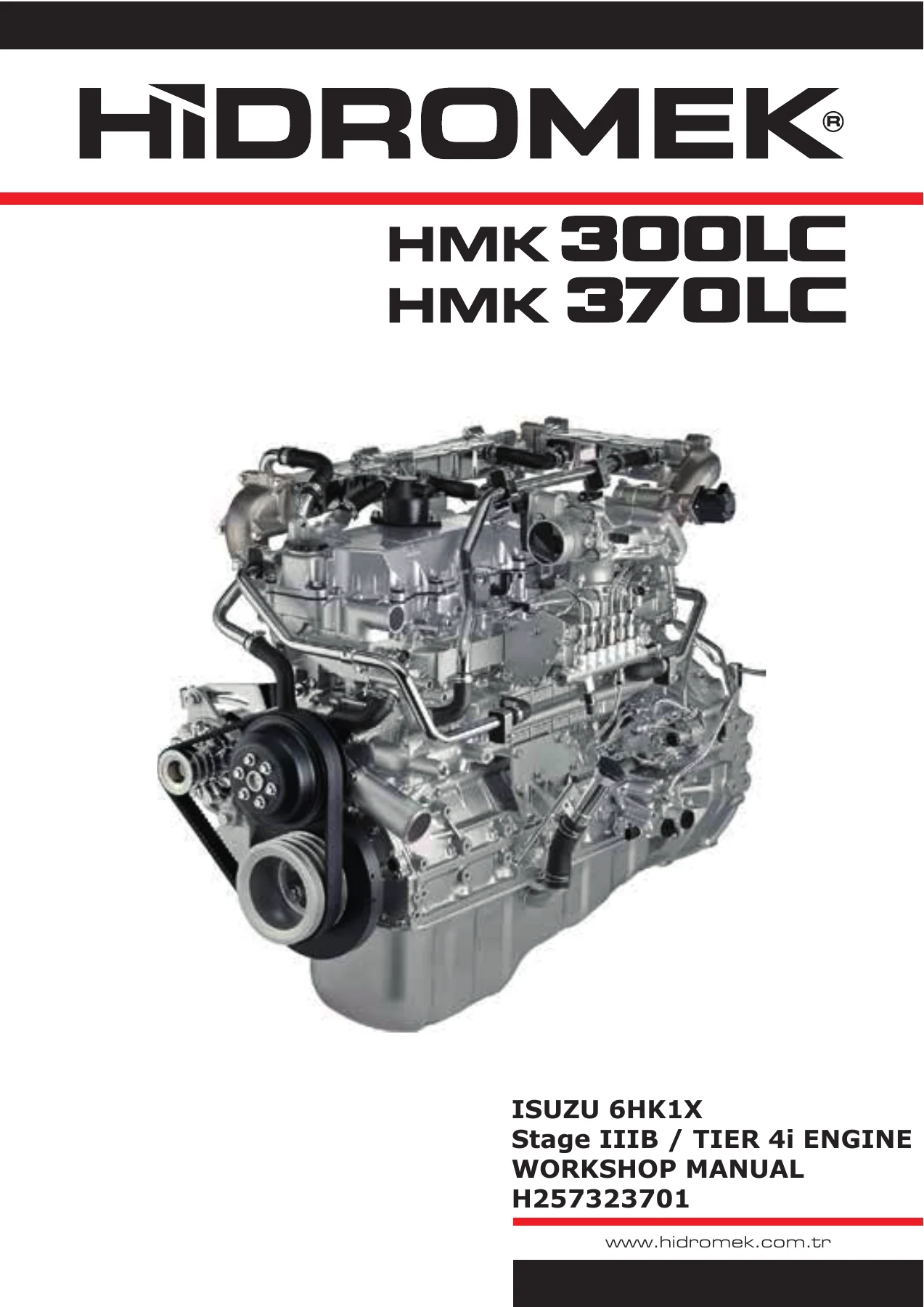
Isuzu 6HK1X Stage IIIB Tier 4i Engine Workshop Manual – Hidromek HMK300LC HMK370LC Service & Repair PDF
Original price was: $89.95.$59.95Current price is: $59.95.
Complete Isuzu 6HK1X Stage IIIB / Tier 4i engine workshop manual for Hidromek HMK300LC and HMK370LC excavators. Covers mechanical, lubrication, cooling, fuel, electrical and inlet/exhaust systems with full diagnostics, specifications and repair procedures. Instant PDF download.
Description
The Isuzu 6HK1X Stage IIIB / Tier 4i Engine Workshop Manual (document number H257323701) is the definitive service, repair and diagnostic reference for the 6-cylinder 6HK1X diesel engine fitted to the Hidromek HMK300LC and Hidromek HMK370LC excavators. This is not a driver’s handbook or a quick-reference pamphlet; it is the full workshop manual that a technician reaches for when an engine is on the stand, when a DTC has to be traced from symptom to root cause, or when a torque figure and a valve clearance value have to be confirmed before a head goes back on. Every chapter is written around the procedures the engine was designed with, so the values, clearances and assembly sequences you read here are the ones that belong in the machine.
File Details
- Manual type: Engine Workshop Manual
- Brand / Equipment: Hidromek
- Engine: Isuzu 6HK1X
- Equipment models covered: Hidromek HMK300LC, Hidromek HMK370LC
- Emissions standard: Stage IIIB / Tier 4i
- Document number: H257323701
- Language: English
- Page count: Approx. 941 pages
- File format: PDF
Chapters Covered
- 01 Engine General Information
- 02 Mechanical
- 03 Engine Lubrication System
- 04 Engine Cooling System
- 05 Engine Fuel System
- 06 Engine Electrical System
- 07 Engine Inlet and Exhaust System
01 Engine General Information
This opening chapter sets up the whole manual. It opens with repair-work safety information, replacement-part and part-number cautions, and an explanation of how the service information is structured so you can read the book the way the manufacturer intended. From there it covers the tools and consumables you will need in the bay: plasti-gauge measuring procedure for connecting rod bearing and crank journal clearances, liquid gasket and thread-locking adhesive selection, and the abbreviations used throughout the document. The chapter then moves into the maintenance precautions that matter most on a modern common-rail diesel, including the strict fuel-system cleanliness rules that keep contaminants out of the injectors. Standard bolt and nut tightening torque tables are included for every thread size from M6 through M24 and for both hex and flange head shapes, along with flare-nut, tapered-thread and connector torque values. Engine primary specifications are laid out for the 6HK1X, and the chapter closes with a very large fault-diagnosis section: DTC reading via diagnostic light blink codes, a full trouble diagnosis workflow, OBD system checks, and the DTC charts themselves covering codes from P0016 camshaft/crankshaft correlation through to P2229 barometric pressure circuit high. Each DTC entry gives setting conditions, the action taken by the ECM, and the relevant circuit description.
02 Mechanical
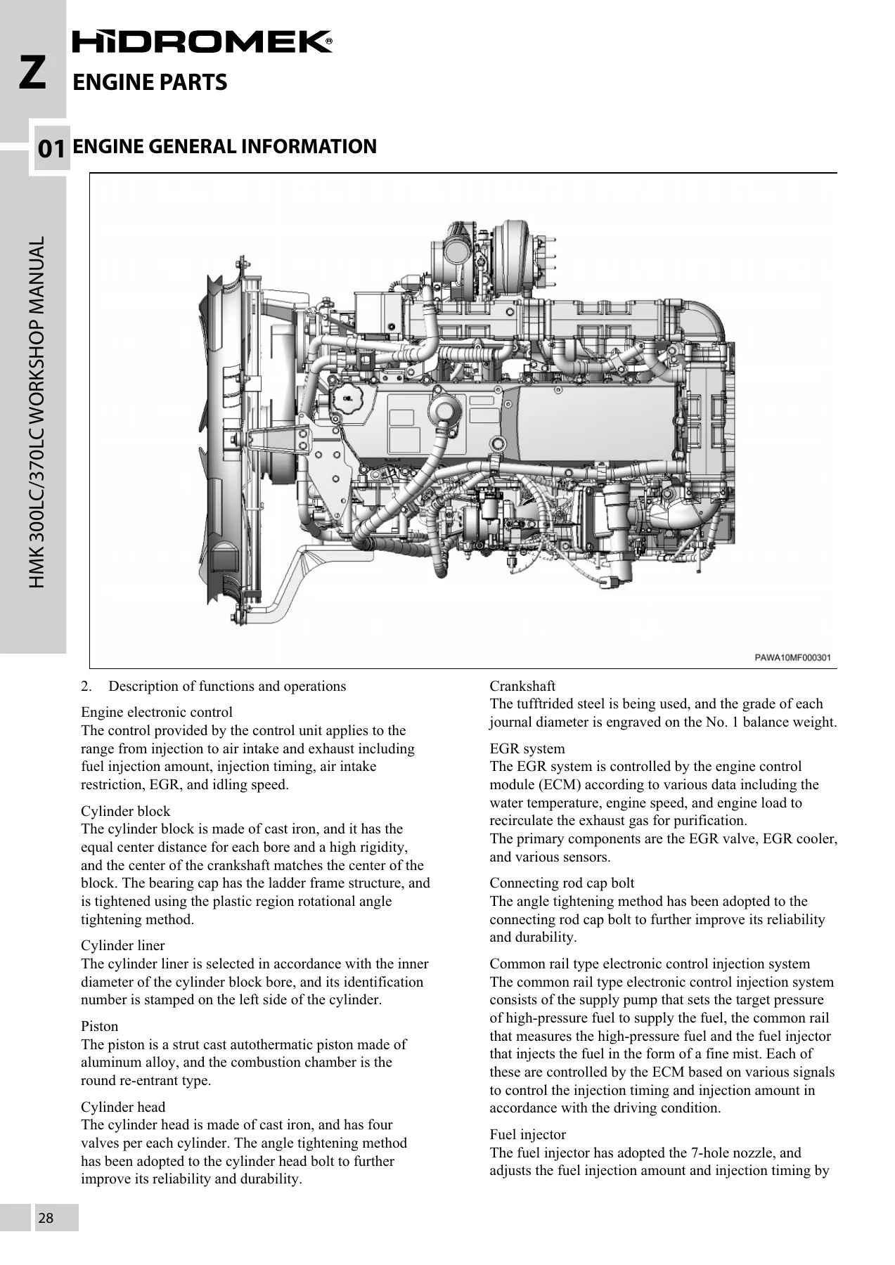
This is the engine mechanical heart of the manual. It covers the cylinder block, cylinder liner, piston, cylinder head, crankshaft and connecting rod assemblies in the level of detail required to overhaul the engine, not just service it. Bearing cap tightening follows the plastic-region rotational angle method, and the cylinder head bolt sequence likewise uses angle tightening, so the exact procedure and values here are critical. The chapter documents the ladder-frame bearing cap structure, cylinder liner selection by bore identification, the round re-entrant combustion chamber shape, and the four-valve-per-cylinder layout. Component location diagrams show the external sensors and actuators around the block and head, including the overheat switch, engine coolant temperature sensor, glow plugs, injectors, boost sensor, boost temperature sensor, IMT sensor, fuel temperature sensor, suction control valve, CKP sensor, oil pressure sensor, oil level switch and fuel pressure sensor.
03 Engine Lubrication System
The lubrication chapter documents the full-flow bypass integrated filter element, the water-cooled oil cooler and the piston coolant oil jet. Oil pump construction and the gear-type pumping elements are shown, along with the delivery valve, relief valve and oil pressure switch settings. Oil pressure inspection is described with the SST oil pressure gauge kit, and the spec of 550 kPa or higher at 2000 rpm is given for a warm engine. The chapter also covers lubrication-system checks, oil level and oil condition inspection, and the leak inspection points around the cylinder head cover and oil pan.
04 Engine Cooling System
The cooling system is documented as a forced-circulation layout built around the water pump, the twin-thermostat housing and the radiator. The manual covers the 2-unit wax-pellet thermostat design, with the bottom bypass unit opening at 82 °C and the inline unit opening at 85 °C, plus jiggle valve details. Component diagrams show the water jacket, drain plug, oil cooler, water pump, drain cock, radiator, cooling fan, radiator cap, radiator reserve tank and EGR cooler. Water pump construction is shown with the fan guide, bearings, impeller and seal unit called out. Cooling system main specifications list the centrifugal impeller pump, the 0.950 pulley ratio, and the thermostat full-open temperatures of 95 °C or 100 °C depending on jiggle valve fitment.
05 Engine Fuel System
The fuel system chapter is built around the electronic common-rail injection system. It describes the supply pump, the common rail with its flow damper, pressure limiter and fuel pressure sensor, and the 7-hole injectors with 0.14 mm inner diameter nozzle holes. Because this is a high-precision system, the manual includes strict handling rules: no re-use of high-pressure and injector pipes, no individual replacement of the pressure limiter or fuel pressure sensor, sealing of every opened port, and the requirement for a clean parts box with cover for eyebolts and gaskets. Fuel filter with sedimenter, pre-fuel filter, electromagnetic pump and fuel filter pressure sensor are all covered, along with the fuel filter clog warning function and the engine speed restriction that comes into play if the filter is left clogged and DTC P0093 is set. Fuel system check procedures and air-removal from the fuel system are described in detail, including the priming-pump sequence that must be followed until no air comes out.
06 Engine Electrical System
The electrical chapter covers the charging system, the starter system, the preheat system and the engine control system. The generator is documented as a brushless, self-rectifier type with built-in IC regulator, rated at 24 V with either 90 A or 50 A output depending on the variant. The starter is a 24 V / 5.0 kW reduction type with magnetic shift, an inner contact gear low-speed mechanism, a 12.8 gear ratio and a 3300 rpm or more no-load speed. The preheat system uses the QOS glow plug system with ECM-controlled energisation. The larger part of this chapter is the engine control system: the ECM I/O table, sensor inputs (CKP, CMP, water temperature, fuel temperature, IAT, IMT, fuel pressure, boost temperature, barometric pressure, accelerator position, EGR position, intake throttle position, DPD differential pressure, exhaust temperature, oil pressure, MAF), switch inputs, actuator and relay outputs, and CAN communication. Fuel injection amount control, injection pressure control, injection timing control, injection rate control, maximum fuel injection amount and the ECM power distribution diagram are all included, along with the 60-pin and 94-pin ECM connector pinout tables that give the pin name and connection for every terminal.
07 Engine Inlet and Exhaust System
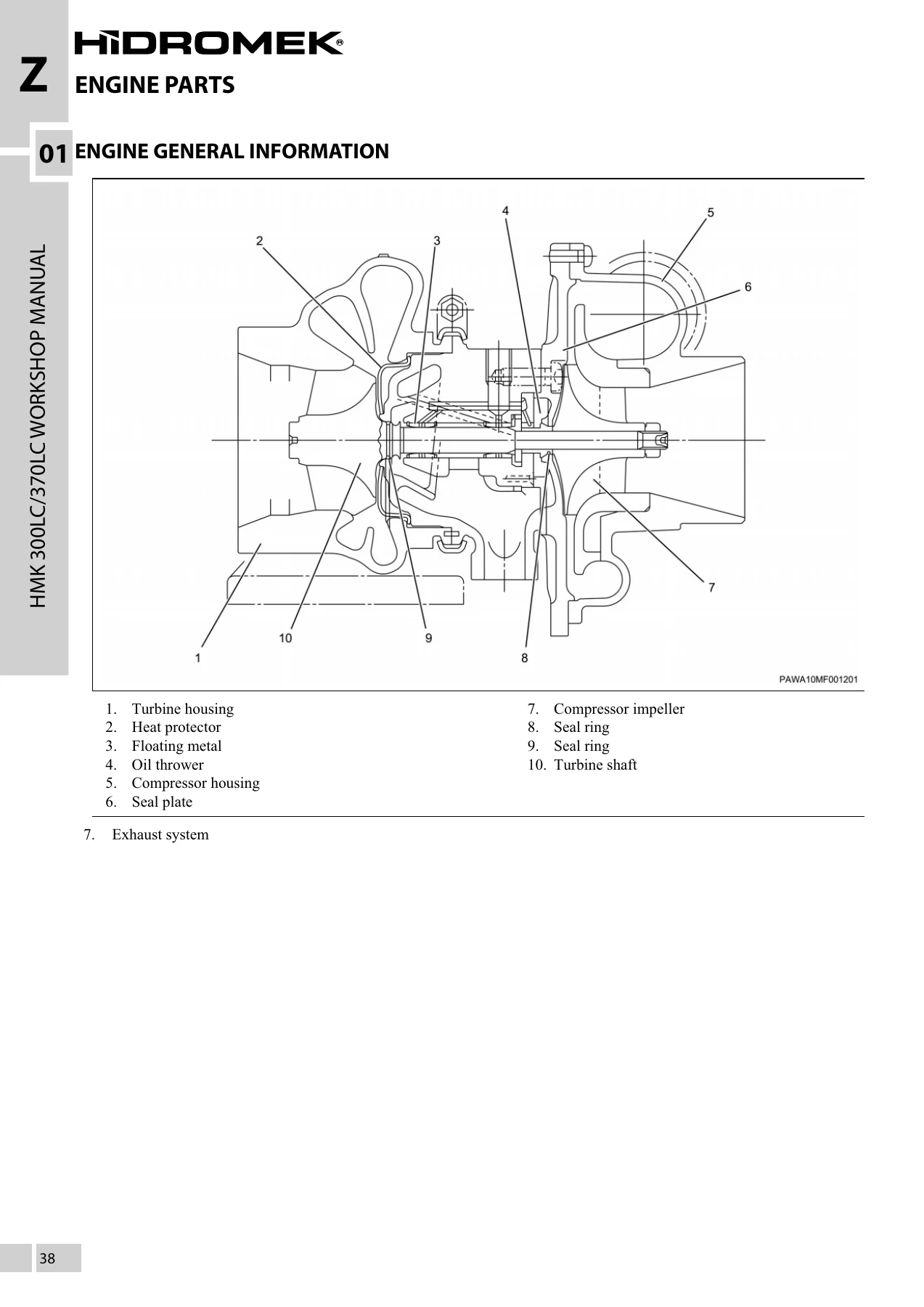
The inlet and exhaust chapter documents the air intake path through the air cleaner, MAF sensor, turbocharger and intake manifold, along with the exhaust side including the DPD assembly, exhaust temperature sensors and exhaust differential pressure sensor. Turbocharger construction is shown with the turbine housing, heat protector, floating metal, oil thrower, compressor housing, seal plate, compressor impeller, seal rings and turbine shaft called out. The turbocharger uses an actuator with a built-in control unit that talks to the ECM over CAN, and the VGS variable nozzle opening angle is adjusted to control boost pressure according to load. The EGR system is documented in full, including the EGR cooler, EGR valve, EGR position sensor and intake throttle valve, with the control logic that determines EGR amount from engine speed and load. The DPD system uses an integrated oxidation catalyst and a filter to collect PM, with automatic regeneration triggered by the exhaust differential pressure sensor or by mileage. Exhaust system checks, air intake system checks and DPD control system checks are all laid out with the values a technician needs to confirm the system is healthy.
What This Workshop Manual Lets You Do
With this manual on hand you can carry out a full engine overhaul on the 6HK1X rather than swapping parts until something works. You can set valve clearance to the correct 0.4 mm cold specification on both intake and exhaust. You can torque the cylinder head, connecting rod cap and main bearing cap bolts using the angle-tightening method the engine is designed for, and measure bearing clearances with plasti-gauge using the correct measurable ranges. You can remove, inspect, clean, measure and reassemble the fuel injectors, common rail, supply pump, suction control valve and high-pressure pipes, and you know which pipes must be replaced rather than reused. You can read and clear DTCs, work through the diagnostic charts from P0016 through P2229, and use the symptom-based diagnosis sections to trace faults that do not set a code, such as engine stalling, rough idling, excessive white or black smoke, low output, abnormal noise, high fuel consumption or high oil consumption. You can service the cooling system, including the twin-thermostat unit and the EGR cooler, and you can inspect and regenerate the DPD system using the exhaust differential pressure and exhaust temperature data. The engine control section lets you understand how the ECM calculates injection quantity, pressure, timing and rate, which is what separates a parts-swapper from a diagnostician.
Why This Manual Matters
The 6HK1X is a Stage IIIB / Tier 4i common-rail diesel, and that means the tolerances are tight and the consequences of guessing are expensive. Reusing a high-pressure fuel pipe that should have been replaced can cause a sealing-surface failure and a fuel leak. Getting the cylinder head bolt sequence wrong can distort the head. Missing a DTC setting condition can send you chasing a sensor that was never at fault. This manual removes the guesswork. The specifications are printed in the units the engine was designed around, the procedures are shown in step order, and the diagnostic charts give the exact thresholds the ECM uses to decide whether a component has failed. For a workshop running Hidromek HMK300LC or HMK370LC excavators, having this document on the shop computer is the difference between a repair that lasts and a comeback.
IMAGES PREVIEW
Instant PDF Delivery
The manual is delivered as a PDF file that downloads immediately after payment. There is no shipping, no waiting for a disc, and no restriction on which device you open it on. Use it on a laptop on the bench, a tablet next to the machine, or print the pages you need for the job and take them into the workshop. Whether you are maintaining one HMK300LC or running a fleet of HMK370LC machines, this Isuzu 6HK1X engine workshop manual keeps the correct procedures and specifications within reach every time the engine comes apart.

Reviews
There are no reviews yet.