★ TRUSTED BY 321,897+ PROFESSIONALS WORLDWIDE
🏢
Trusted Business
Verified & Licensed
🛡️
Virus Free Files
100% Safe Downloads
🔒
Secure Payment
SSL Protected
Instant Delivery
Available Immediately
Sale!

JLG 742 943 1043 1055 1255 Telehandler Service Repair Manual – 2023 PDF

Original price was: $39.95.Current price is: $24.95.

Complete 588-page JLG service repair manual for 742, 943, 1043, 1055 and 1255 telehandlers. Covers Cummins QSF3.8 engines, hydraulics, electricals, fault codes, removal/installation, disassembly and schematics. Instant PDF download.

Instant PDF Download
Available immediately
💾
Save to Your Device
Download & keep forever
🛡️
Antivirus Scanned
100% virus-free
🌍
Trusted Worldwide
175,000+ customers

Description

JLG 742, 943, 1043, 1055, 1255 Telehandler Service Repair Manual

This is the complete JLG 742, 943, 1043, 1055, 1255 Telehandler Service Repair Manual, document number 31211964, Revision B, dated May 15, 2023. At 588 pages, it is the full workshop-level reference used to service, diagnose, repair and maintain these five telehandler models. Whether you are a professional equipment mechanic, a fleet maintenance technician or an owner-operator handling your own repairs, this JLG service manual delivers the procedures, specifications and system-level detail needed to keep the machine running correctly.

The JLG 742 943 1043 1055 1255 service manual covers the Cummins QSF3.8 diesel engine in its 74 HP (55 kW), 110 HP (82 kW) and 130 HP (97 kW) configurations, both Ultra Low Sulfur (ULS) and Low Sulfur (LS) fuel variants. It addresses the major systems of the machine: hydraulics, electricals, powertrain, boom, cab, engine, transmission and schematics. Every section is organized to support real repair work, from routine maintenance through component removal and disassembly.

File Details

  • Manual type: Service Repair Manual
  • Brand: JLG
  • Models covered: 742, 943, 1043, 1055, 1255
  • Document number: 31211964
  • Revision: Rev B
  • Date: May 15, 2023
  • Language: English
  • Page count: 588
  • File format: PDF

Chapters Covered

The JLG 742 943 1043 1055 1255 repair manual is organized into the following top-level sections:

  • Section 1 — Safety: general safety, safety information, hazards, decals, machine verification
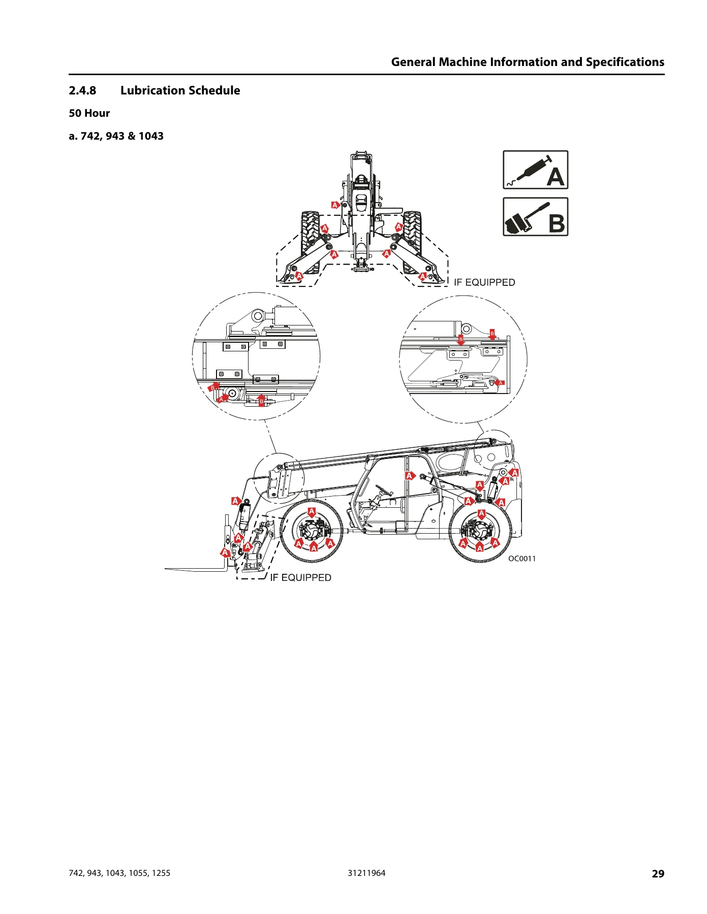
  • Section 2 — General Machine Information and Specifications: travel speed, hydraulic cylinder performance, cylinder drift, steering angles, electrical system, transmission performance, engine performance, tires, temperature chart, serial number location, fluids and lubrication, capacities, lubrication schedule
  • Section 3 — Maintenance and Inspection Schedules: preparation, inspection and maintenance, service guidelines, preventive maintenance schedule, pins and composite bearing repair, tires and wheels, brake maintenance, DEF tank inspection, boom inspection, hydraulic filter replacement
  • Section 4 — Testing, Calibrations and Special Procedures: special tools, testing procedures, calibration procedures, special procedures including emergency boom lowering, towing, hydraulic pressures, boom section adjustment, chain inspection, RAS system, accumulator charging
  • Section 5 — System Software: Load Stability Indicator (LSI), JLG Analyzer, analyzer software accessibility, multifunction display
  • Section 6 — Fault Codes: engine diagnostic codes, machine fault codes version P21.0 with help comments and trigger/latch conditions
  • Section 7 — Hydraulics: safety information, theories of operation, hydraulic component terminology, torque valves and cylinder torque specifications
  • Section 8 — Electricals: general information, electrical connectors, component terminology, harness layouts, board layouts, telematics gateway
  • Section 9 — Removal and Installation: wheels, drive assembly, boom, operator cab components, engine, transmission, hydraulic valves, hydraulic cylinders, implement pump, electrical components
  • Section 10 — Disassembly and Assembly: drive assembly, boom section teardown and reassembly for both 3-section and 4-section booms, cab, engine components, hydraulic cylinders, hydraulic valves, hydraulic reservoir
  • Section 11 — Torque/Connection Information: hydraulic fittings, assembly instructions for NPTF, BSPT, JIC, SAE, ORFS, MBTL/MBTS, bulkhead, ORB, MFF, BSPP and flange connections, plus SAE and metric torque charts
  • Section 12 — Schematics: hydraulic schematics for each model and electrical system schematics

Complete PDF Bookmark Tree

Complete Bookmarks

The complete bookmarks in the “JLG 742 943 1043 1055 1255 Telehandler Service Repair Manual – 2023 PDF” are as follows:

31211964_B_742, 943, 1043, 1055, 1255_JLG_Service_Englishp. 1
Effectivity Page (reference)p. 3
Read This First (task)p. 5
Modificationsp. 5
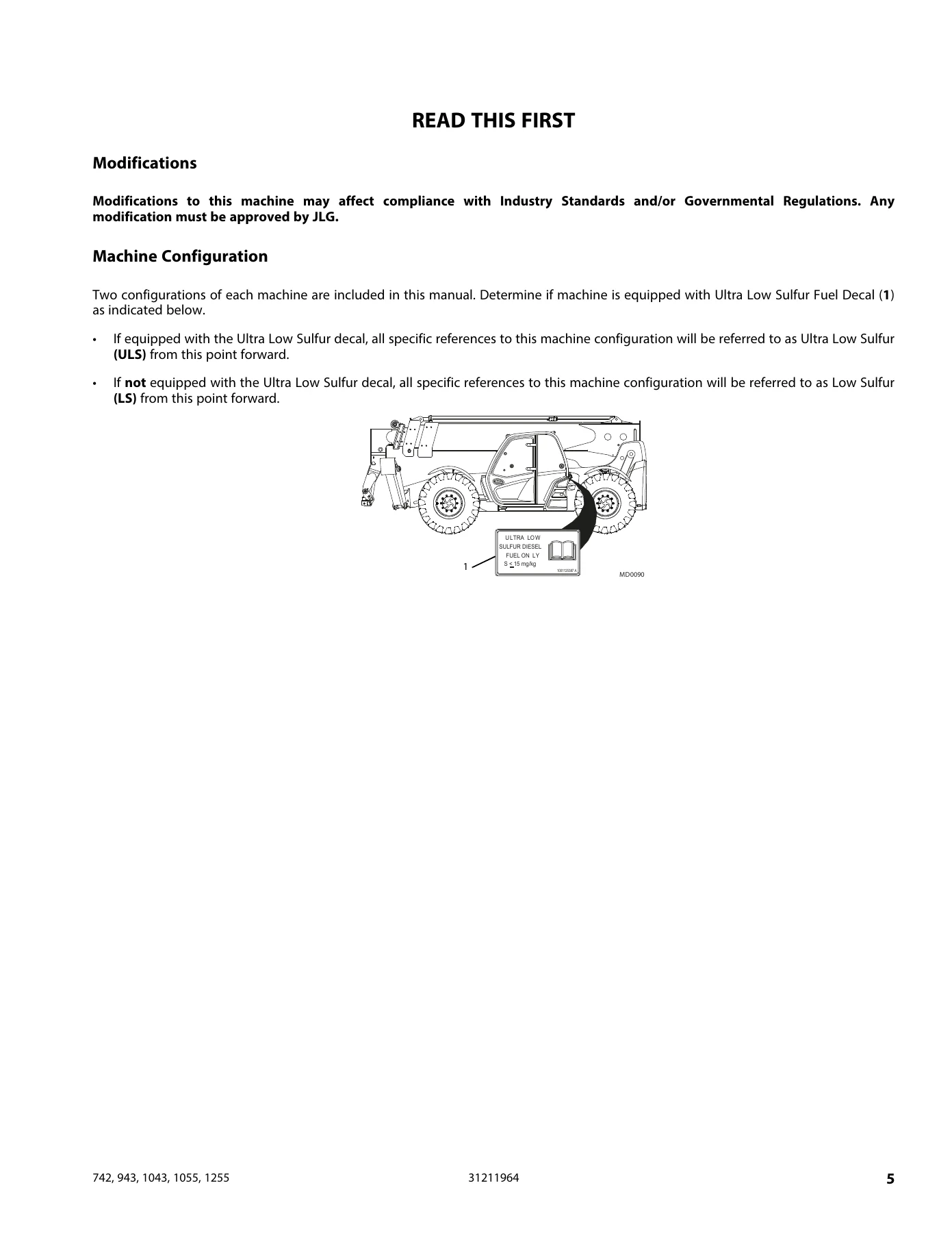
Machine Configurationp. 5
Table of Contentsp. 7
Safetyp. 11
General (concept)p. 11
1.1.1 Disclaimerp. 11
1.1.2 Operation & Safety Manualp. 11
1.1.3 Do Not Operate Tagsp. 11
Safety Information (concept)p. 11
1.2.1 Safety Alert System and Signal Wordsp. 12
Safety Hazards (task)p. 12
1.3.1 Personal Hazardsp. 12
1.3.2 Equipment Hazardsp. 12
1.3.3 General Hazardsp. 12
1.3.4 Operational Hazardsp. 13
Safety Decals (concept)p. 13
Machine Verification (concept)p. 13
General Machine Information and Specificationsp. 15
Specificationsp. 15
2.1.1 Travel Speedp. 15
2.1.2 Hydraulic Cylinder Performancep. 15
2.1.3 Cylinder Driftp. 16
2.1.4 Steering Angle Specificationsp. 16
2.1.5 Electrical Systemp. 17
2.1.6 Transmission Performance Specificationsp. 18
2.1.7 Engine Performance Specificationsp. 18
2.1.8 Tiresp. 19
Machine Temperature Chartp. 21
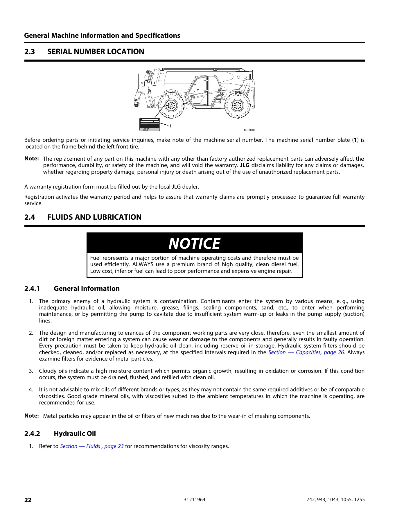
Serial Number Locationsp. 22
Fluids and Lubricationp. 22
2.4.1 General Informationp. 22
2.4.2 Hydraulic Oilp. 22
2.4.3 Changing Hydraulic Oilp. 23
2.4.4 Lubrication Specificationsp. 23
2.4.5 Fluids (if equipped for ULS)p. 23
2.4.6 Fluids (if equipped for LS)p. 24
2.4.7 Capacitiesp. 26
2.4.8 Lubrication Schedulep. 29
Maintenance and Inspection Schedulesp. 35
Machine Preparation, Inspection, and Maintenancep. 35
3.1.1 Preparation, Inspection, and Maintenancep. 35
3.1.2 Pre-Start Inspectionp. 35
3.1.3 Pre-Delivery Inspectionp. 35
Service and Guidelinesp. 35
3.2.1 Generalp. 35
3.2.2 Safety and Workmanshipp. 35
3.2.3 Cleanlinessp. 35
3.2.4 Components Removal and Installationp. 35
3.2.5 Component Disassembly and Reassemblyp. 36
3.2.6 Pressure-Fit Partsp. 36
3.2.7 Bearingsp. 36
3.2.8 Gasketsp. 36
3.2.9 Bolt Usage and Torque Applicationp. 36
3.2.10 Hydraulic Lines and Electrical Wiringp. 36
3.2.11 Hydraulic Systemp. 36
3.2.12 Lubricationp. 36
3.2.13 Batteryp. 37
3.2.14 Welding on JLG Equipmentp. 37
Preventive Maintenance and Inspection Schedulep. 37
3.3.1 Every 10 Hoursp. 37
3.3.2 First 50 Hoursp. 38
3.3.3 Every 50 Hoursp. 38
3.3.4 First 250 Hoursp. 38
3.3.5 Every 250 Hoursp. 38
3.3.6 First 500 Hours or 1 Yearp. 38
3.3.7 Every 500 Hoursp. 39
3.3.8 Every 750 Hoursp. 39
3.3.9 Every 1000 Hoursp. 39
3.3.10 Every 1500 Hoursp. 39
3.3.11 Every 2000 Hoursp. 40
3.3.12 Every 4000 Hoursp. 40
3.3.13 Every 5000 Hoursp. 40
Pins and Composite Bearing Repair Guidelinesp. 40
3.4.1 Filament Wound Bearingsp. 40
Tires & Wheelsp. 41
3.5.1 Tire Inflationp. 41
3.5.2 Tire Damagep. 41
Brake Maintenancep. 42
3.6.1 Service Brake Bleedingp. 42
3.6.2 Service Brake Testp. 45
3.6.3 Park Brake Bleedingp. 45
3.6.4 Brake Inspectionp. 45
3.6.5 Steering Angle Adjustmentp. 45
DEF Tank Inspectionp. 46
Boom Inspection and Maintenancep. 46
3.8.1 Boom Wear Padsp. 46
Hydraulic Filter Replacementp. 47
3.9.1 Hydraulic Filterp. 47
Testing, Calibrations and Special Proceduresp. 49
Special Toolsp. 49
4.1.1 Multimeterp. 49
4.1.2 Thread Locking Compoundp. 52
4.1.3 Tools Catalogp. 52
Testing Proceduresp. 52
4.2.1 Starterp. 52
4.2.2 Fuel Level Senderp. 53
Calibration Proceduresp. 53
4.3.1 JLG Analyzerp. 53
4.3.2 Boom Angle Sensor Calibrationp. 54
4.3.3 LSI System Calibrationp. 54
4.3.4 LMIS (Load Management Indicator System) Calibrationp. 55
4.3.5 Attachment Recognition Calibrationp. 56
4.3.6 Brake Pedal Calibrationp. 56
Special Proceduresp. 57
4.4.1 Emergency Boom Lowering Procedurep. 57
4.4.2 Precision Gravity Lower System (PGLS)p. 63
4.4.3 Towing a disabled machinep. 64
4.4.4 Hydraulic Reservoirp. 67
4.4.5 Diesel Exhaust Fluid (DEF) System Cleaning (if equipped for ULS)p. 71
4.4.6 Accumulatorsp. 71
4.4.7 Hydraulic Pressure Settings and Adjustmentsp. 73
4.4.8 Cylinder Pressure Checkingp. 74
4.4.9 Cylinder Drift Testp. 74
4.4.10 Hydraulic Circuitsp. 75
4.4.11 Hydraulic Pressuresp. 75
4.4.12 Pressure Specificationp. 76
4.4.13 Boom Sections Adjustment – 742, 943, 1043p. 82
4.4.14 Boom Sections Adjustment – 1055, 1255p. 83
4.4.15 Boom Extend and Retract Chainsp. 85
4.4.16 Rear Axle Stabilization (RAS) Systemp. 88
System Softwarep. 91
Load Stability Indicator (LSI) (If Equipped)p. 91
5.1.1 Load Stability Indicatorp. 91
5.1.2 LSI Sensorp. 92
JLG Analyzerp. 97
5.2.1 Machine Data Accessp. 97
5.2.2 Hand Held Analyzerp. 97
5.2.3 Mobile Analyzerp. 98
5.2.4 Analyzer Software (Version P21.0)p. 99
Analyzer Software Accessibilityp. 108
5.3.1 Access Levelp. 108
5.3.2 Diagnosticsp. 108
5.3.3 Machine Set-Upp. 109
5.3.4 Personalitiesp. 113
5.3.5 Operator Toolsp. 115
5.3.6 Calibrationsp. 117
Multifunction display (If Equipped)p. 123
5.4.1 Technical Specificationp. 123
5.4.2 Multifunction Display and Control Buttonsp. 123
5.4.3 Main Menup. 125
5.4.4 Setup and Maintenancep. 128
5.4.5 Troubleshootingp. 132
Fault Codesp. 133
Introductionp. 133
Engine Diagnosticsp. 133
Machine Fault Codesp. 167
Hydraulicsp. 283
General Information and Safetyp. 283
Theories of Operationp. 284
7.2.1 Cylindersp. 284
7.2.2 Valvesp. 284
Hydraulic Componentp. 285
Torque Valuesp. 285
7.4.1 Cylinder Torque Specificationsp. 285
Electricalsp. 289
General Informationp. 289
8.1.1 Applying Silicone Dielectric Compound to Electrical Connectionsp. 289
8.1.2 Dielectric Grease Applicationp. 289
8.1.3 Electrical Connector Examplesp. 290
Electrical Connectorsp. 292
Electrical Component Terminologyp. 294
8.3.1 General Overviewp. 294
Harness Layoutsp. 294
Board Layoutsp. 294
8.5.1 Cab Power Distribution Boardp. 294
8.5.2 Frame Power Distribution Boardp. 298
8.5.3 Option 1 Distribution Boardp. 300
8.5.4 Option 2 Distribution Boardp. 302
8.5.5 Engine Harness Fuses and Relaysp. 304
Telematics Gatewayp. 304
8.6.1 Component Locationsp. 305
8.6.2 Telematics-Ready (TCU) Plugp. 305
8.6.3 Telematics Gateway Harness Breakdownp. 306
Removal and Installationp. 311
Wheelsp. 311
9.1.1 Removing Wheel and Tire Assembly from Machinep. 311
9.1.2 Installing Wheel and Tire Assembly onto Machinep. 311
Drive Assemblyp. 312
9.2.1 Axle, Drive Shaft and Wheel Component Terminologyp. 312
9.2.2 Axle Assembly and Drive Shaft Troubleshootingp. 313
9.2.3 Axle Serial Numberp. 315
9.2.4 Axle Specifications and Maintenance Informationp. 315
9.2.5 Axle Replacementp. 316
9.2.6 Drive Shaftsp. 319
Boomp. 323
9.3.1 Troubleshootingp. 325
9.3.2 Boom Systemp. 326
9.3.3 Boom Removal/Installationp. 327
9.3.4 Manual Couplerp. 330
9.3.5 Hydraulic Couplerp. 332
9.3.6 Forksp. 333
9.3.7 Boom Angle Sensorp. 334
9.3.8 Boom Wear Pad Installation, Lubricationp. 336
9.3.9 General Accumulator Information (Boom Ride Control)p. 338
9.3.10 Boom Prop (If Equipped) (742, 943, 1043)p. 339
9.3.11 Boom Prop (If Equipped) (1055, 1255)p. 340
Cabp. 342
9.4.1 Serial Number Platep. 343
9.4.2 Cab Removal/Installationp. 343
9.4.3 Steering Wheelp. 346
9.4.4 Electronic Throttle Pedalp. 347
9.4.5 Joystick Assemblyp. 348
9.4.6 Ignition Key Switchp. 349
9.4.7 Dash Switchesp. 351
9.4.8 Front Windshield Wiper Motorp. 351
9.4.9 Rear Window Wiper Motorp. 353
9.4.10 Roof Window Wiper Motorp. 354
9.4.11 Washer Fluid Reservoirp. 356
9.4.12 Heater System (if equipped)p. 357
9.4.13 Heater and A/C System (if equipped)p. 359
9.4.14 Multifunction Displayp. 361
9.4.15 Multifunction Displayp. 362
Enginep. 364
9.5.1 Component Terminologyp. 364
9.5.2 Engine Serial Numberp. 367
9.5.3 Specifications and Maintenance Informationp. 367
9.5.4 Engine Replacementp. 367
9.5.5 Surge Tank Capp. 370
9.5.6 Thermostat Replacementp. 371
9.5.7 Radiator Assembly Replacementp. 372
9.5.8 Engine Coolant Temperature Sensorp. 374
9.5.9 Hydraulic Oil Reservoir Removal/ Installationp. 375
9.5.10 Fuel Systemp. 378
9.5.11 Fuel Tankp. 384
9.5.12 Engine Exhaust Systemp. 386
9.5.13 Air Cleaner Assemblyp. 396
9.5.14 Starterp. 398
9.5.15 Alternatorp. 399
Transmissionp. 400
9.6.1 Component Terminologyp. 400
9.6.2 Transmission Serial Numberp. 401
9.6.3 Specifications and Maintenance Informationp. 401
9.6.4 Transmission Replacementp. 401
9.6.5 Transmission Fluid/Filter Replacementp. 403
9.6.6 Transmission Fluid Level Checkp. 404
9.6.7 Transmission Cooler Thermal Bypass Valvep. 405
9.6.8 Transmission Temperature Sensorp. 406
9.6.9 Transmission Solenoid Valvesp. 407
9.6.10 Torque Converter Diaphragmp. 408
9.6.11 Reverse Alarmp. 408
Hydraulic Valvesp. 409
9.7.1 Main Control Valvep. 409
9.7.2 Priority Valve – 742, 943, 1043, 1055, 1255p. 410
9.7.3 Service Brake Valvep. 411
9.7.4 Steering Orbital Valvep. 414
9.7.5 Frame Leveling Valve or Outrigger/ Frame Leveling Valve (if equipped)p. 414
9.7.6 Steer Select Valvep. 415
9.7.7 Park Brake Valvep. 416
Hydraulic Cylindersp. 418
9.8.1 General Cylinder Instructionsp. 418
9.8.2 Cylinder Pressure Checkingp. 418
9.8.3 Steering Cylindersp. 418
Hydraulic Pumpp. 419
9.9.1 Pump Replacementp. 419
Electrical Componentsp. 421
9.10.1 Batteryp. 421
9.10.2 Inspectionp. 421
9.10.3 Removalp. 422
9.10.4 Installationp. 422
9.10.5 Disconnectp. 422
9.10.6 Connectp. 422
9.10.7 Electrical Master Switchp. 423
Disassembly and Assemblyp. 425
Drive Assemblyp. 425
10.1.1 Axle Assemblyp. 425
10.1.2 Transmission Assemblyp. 425
Boomp. 425
10.2.1 Boom Assembly Maintenance – 742, 943, 1043p. 425
10.2.2 Third Boom Section Removal/ Installation Only – 742, 943, 1043p. 434
10.2.3 Boom Assembly Maintenance – 1055, 1255p. 436
10.2.4 Fourth Boom Section Removal/Installation Only – 1055, 1255p. 448
10.2.5 Hose Carrier Assembly – 1055, 1255p. 450
Cabp. 452
Engine Componentsp. 452
10.4.1 Engine Disassembly, Inspection and Servicep. 452
10.4.2 Fuel Tankp. 452
Hydraulic Cylindersp. 453
10.5.1 General Cylinder Disassemblyp. 453
10.5.2 General Cylinder Assembly Instructionsp. 454
10.5.3 Cylinder Cleaning Instructionsp. 454
10.5.4 Cylinder Inspectionp. 454
Hydraulic Valvesp. 455
10.6.1 Main Control Valvep. 455
10.6.2 Priority Valve – 742, 943, 1043, 1055, 1255p. 456
10.6.3 Frame Leveling Valve or Outrigger/ Frame Leveling Valve (if equipped)p. 457
10.6.4 Steer Select Valvep. 458
Hydraulic Componentsp. 459
10.7.1 Hydraulic Oil Reservoirp. 459
Torque/Connection Informationp. 461
Hydraulic Fittingsp. 461
11.1.1 Definitionsp. 461
11.1.2 Assembly Instructions for American Standard Pipe Thread Tapered (NPTF) Connectionsp. 464
11.1.3 Assembly Instructions for British Standard Pipe Thread Tapered (BSPT) Connectionsp. 466
11.1.4 Assembly Instructions for 37° (JIC) Flare Fittingsp. 468
11.1.5 Assembly Instructions for 45° SAE Flare Fittingsp. 471
11.1.6 Assembly Instructions for O-Ring Face Seal (ORFS) Fittingsp. 474
11.1.7 Assembly Instructions for DIN 24° Flare Bite Type Fittings (MBTL and MBTS)p. 477
11.1.8 Assembly Instructions for Bulkhead (BH) Fittingsp. 480
11.1.9 Assembly Instructions for O-Ring Boss (ORB) Fittingsp. 485
11.1.10 Assembly Instructions for Adjustable Port End Metric (MFF) Fittingsp. 498
11.1.11 Assembly Instructions for Metric ISO 6149 (MPP) Port Assembly Stud Endsp. 511
11.1.12 Assembly Instructions for Adjustable Port End (BSPP) Fittingsp. 514
11.1.13 Assembly Instructions for Flange Connections (FL61 and FL62)p. 527
11.1.14 Double Wrench Methodp. 532
11.1.15 FFWR and TFFT Methodsp. 532
11.1.16 Adjustable Stud End Assemblyp. 533
11.1.17 O-ring Installation (Replacement)p. 534
Torque Chartsp. 535
11.2.1 SAEp. 535
11.2.2 Metricp. 547
Schematicsp. 551
Hydraulic Schematicsp. 551
12.1.1 742p. 551
12.1.2 943p. 556
12.1.3 1043p. 558
12.1.4 1055, 1255p. 560
Electrical Schematicsp. 562
12.2.1 742, 943, 1043p. 562
12.2.2 1055, 1255p. 575

Beyond the table of contents, this JLG telehandler service manual goes deep into the machine. The fault code chapter alone covers hundreds of SPN/FMI engine diagnostic codes and machine fault codes with detailed trigger conditions, latch conditions and corrective actions. The hydraulic section includes pressure specifications with test port locations and adjustment procedures. The electrical section includes board layouts, fuse and relay assignments, connector pinouts and harness routing. The removal and installation section walks through major components step by step, and the disassembly and assembly section provides the internal teardown detail needed for boom chain replacement, cylinder resealing and component overhaul.

The JLG 742 943 1043 1055 1255 service repair manual also includes calibration procedures for the LSI system, boom angle sensor, LMIS, attachment recognition and brake pedal. Special procedures cover emergency boom lowering with and without the Precision Gravity Lower System (PGLS), manually releasing and resetting the park brake for towing, hydraulic reservoir service, DEF system cleaning and accumulator pre-charging. Maintenance schedules break down tasks by interval — 10 hours, 50 hours, 250 hours, 500 hours, 750 hours, 1000 hours, 1500 hours, 2000 hours, 4000 hours and 5000 hours.

Why This JLG Service Manual Matters

Working on a telehandler without the correct service information is a fast way to create bigger problems. Torque values, pressure settings, calibration sequences and fault code diagnostics all have to be right. This JLG 742 943 1043 1055 1255 repair manual gives you the actual specifications and step-by-step procedures from the manufacturer’s service documentation. It covers the Cummins QSF3.8 engine and the machine systems around it — hydraulics, electricals, transmission, axles, boom and cab — so you can diagnose accurately, repair correctly and verify the machine operates properly afterward.

IMAGES PREVIEW

JLG 742 943 1043 1055 1255 Telehandler Service Repair Manual - 2023 PDF — PDF page 5 preview
JLG 742 943 1043 1055 1255 Telehandler Service Repair Manual - 2023 PDF — PDF page 22 preview
JLG 742 943 1043 1055 1255 Telehandler Service Repair Manual - 2023 PDF — PDF page 29 preview

Because the manual covers five models across multiple engine ratings and both ULS and LS configurations, it is a single reference for a mixed fleet. Instead of hunting down separate documents for each machine, you have the 742, 943, 1043, 1055 and 1255 service information in one place. The schematics section includes hydraulic and electrical diagrams to trace circuits and diagnose faults, and the torque charts give you the tightening specifications for standard and metric fasteners in SAE and metric grades.

Instant PDF Delivery

This JLG 742 943 1043 1055 1255 telehandler service manual is delivered as an instant PDF download. There is no shipping, no waiting for a physical book and no restrictions on where you can use it. Open it on a laptop in the shop, a tablet at the machine or a phone in the field. Print the pages you need for the job at hand. The PDF format keeps the document portable and easy to search, so you can move between sections quickly when you are in the middle of a repair.

Whether you are servicing a 742, diagnosing a fault on a 1055 or overhauling the boom on a 1255, this service repair manual provides the technical depth to get the work done. It covers the procedures, specifications, fault codes and diagrams that support real maintenance and repair — not just routine checks, but the detailed work that keeps these machines productive.
Reviews

There are no reviews yet.

Be the first to review “JLG 742 943 1043 1055 1255 Telehandler Service Repair Manual – 2023 PDF”

What Our Customers Say

★★★★★ Live reviews from customers
Loading customer reviews...
0
    0
    Your Cart
    Your cart is emptyReturn to Shop
    🛒
    Recently Purchased
    🕒 verified order