★ TRUSTED BY 321,897+ PROFESSIONALS WORLDWIDE
🏢
Trusted Business
Verified & Licensed
🛡️
Virus Free Files
100% Safe Downloads
🔒
Secure Payment
SSL Protected
Instant Delivery
Available Immediately
Sale!

JCB 426, 436, 446 Wheeled Loading Shovel Service Manual PDF

Original price was: $44.95.Current price is: $27.95.

Complete 1095-page JCB workshop service manual for the 426, 436 and 446 wheeled loading shovels. Covers engine, ZF transmission, axles, brakes, hydraulics, electrics, steering and bodywork with full dismantling, testing and adjustment procedures.

Instant PDF Download
Available immediately
💾
Save to Your Device
Download & keep forever
🛡️
Antivirus Scanned
100% virus-free
🌍
Trusted Worldwide
175,000+ customers

Description

JCB 426, 436, 446 Wheeled Loading Shovel Service Manual – Publication 9803/4160-15

This JCB 426, 436, 446 Wheeled Loading Shovel Service Manual is the complete workshop publication issued by JCB Technical Publications for the 426, 436 and 446 wheeled loading shovels. Running to 1095 pages, the JCB 426 436 446 service manual covers the whole machine – Perkins and Cummins engines, ZF powershift transmission, drive axles, brake system, Rexroth hydraulic pumps and loader valve block, electrical system, hydraulic steering and bodywork – with the dismantling, overhaul, pressure testing and adjustment procedures a service engineer needs at the bench.

File Details

  • Manual type: Service / Workshop Manual
  • Brand: JCB
  • Models covered: 426, 436, 446 Wheeled Loading Shovels
  • Publication number: 9803/4160-15
  • Publisher: JCB Technical Publications, JCB Service
  • Language: English
  • Page count: 1095 pages
  • File format: PDF

IMAGES PREVIEW

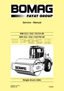
JCB 426, 436, 446 Wheeled Loading Shovel Service Manual PDF — PDF page 1 preview
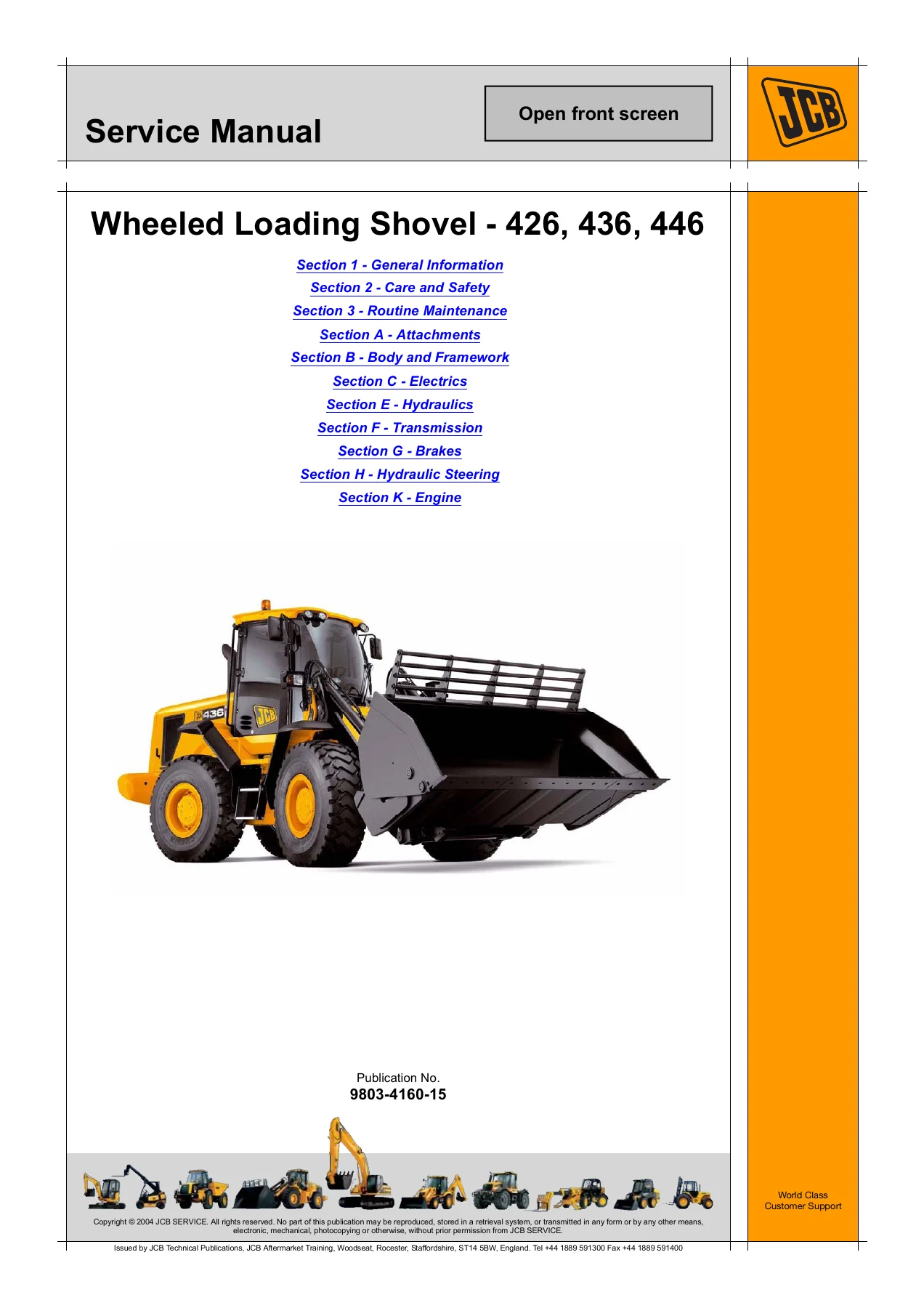
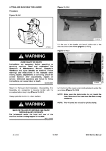
JCB 426, 436, 446 Wheeled Loading Shovel Service Manual PDF — PDF page 8 preview
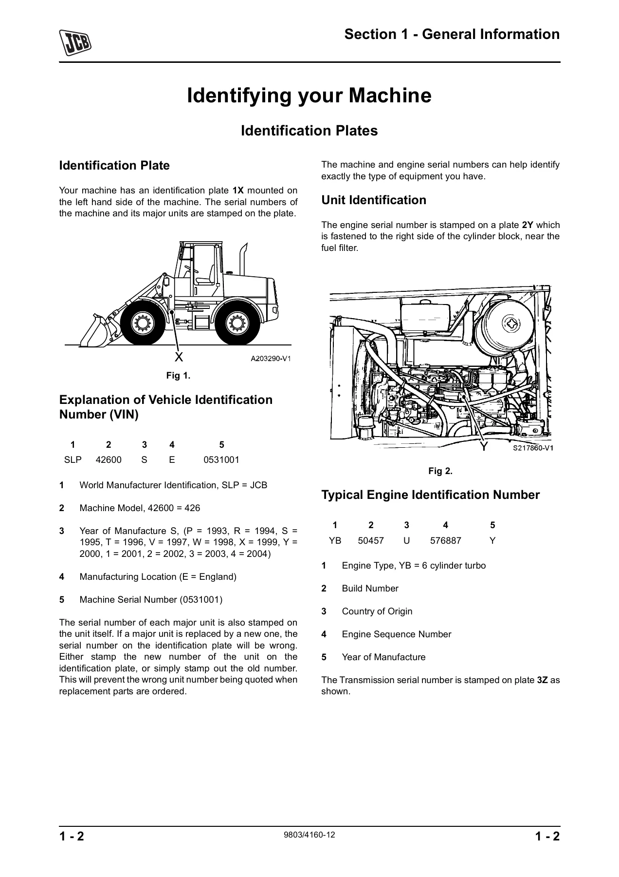
JCB 426, 436, 446 Wheeled Loading Shovel Service Manual PDF — PDF page 83 preview

Chapters Covered in This JCB Wheeled Loader Service Manual

  • Section 1 – General Information: introduction, identifying your machine, identification plates, VIN explanation, unit identification, torque settings for zinc plated, UNF Grade S, metric grade 8.8 and rivet nut fasteners, service tools by section, sealing and retaining compounds
  • Section 2 – Care and Safety: safety notices, safety check list, general safety, operating safety, maintenance safety, safety decals
  • Section 3 – Routine Maintenance: service requirements, service schedules, lubricants and capacities, cleaning, checking for damage, ROPS/FOPS checks, articulation lock, loader arm safety strut, greasing, automatic greasing system, access panels, heating and ventilation, electrical system, engine, fuel system, hydraulic system, transmission, wheels and tyres, window washers
  • Section A – Attachments: quick release couplings, connecting and disconnecting flat face couplings, do’s and don’ts
  • Section B – Body and Framework: air conditioning option, basic operation, R134a refrigerant, system control, fault finding, service procedures, rivet nuts, refrigerant charging and discharging, pressure switches, early and later type air conditioning units, cab glazing and direct glazing, ROPS/FOPS structure, rear bodywork removal and replacement, centre pivot removal and replacement, cooling pack removal, dismantling and assembly
  • Section C – Electrics: general electrical data, light bulbs, fuses and relays by serial range, using a multimeter, battery maintenance and testing, specific gravity testing, alternator charging tests, starter motor starting circuit tests, HC11 and C164 EMS display panels, warning lights, automatic engine shutdown, 24-12 volt power distribution board, fault finding techniques, harness routing, wire tracing, component testing, schematic circuits, harness and wire number identification, connector locations, harness drawings, EMS software tools, alternator and starter motor overhaul
  • Section E – Hydraulics: technical data by serial range, general description, hydraulic schematic symbols, circuit diagrams, pump operation, pump pressure/flow regulator valves, start up valve, loader valve operation for arms raise/lower, shovel float, shovel tip and crowd on 4-ram and Z-bar loaders, compensator spool operation, auxiliary services, servo pressure regulating valve, Automatic Carry Control System (ACCS), electronic emergency steering, hydraulic fault finding, hydraulic contamination, venting the hydraulic pressure, connecting and disconnecting hoses, positional type hydraulic adaptors, flow and pressure tests, idle control setting, hydraulic cooling fan setting, reversing fan software, pump removal and overhaul, emergency steering pump, cooling fan motors, ram dismantling and assembly, JCB ram sealing procedure, Z rams and 436ZX ram procedures
  • Section F – Transmission: technical data for 426 and 436, drive axle ratios, tyre sizes and pressures, transmission gear ratios, stall testing, WG150 and WG200 powershift transmission control valve, charge pump, coaxial and lateral power take-off, layshaft, final drive, multi-disc clutches K4/K3, KR/K2 and KV/K1, emergency steering pump, WG160 and WG190 main components, oil circulation, power flow for forward and reverse speeds, test points, electro-hydraulic shift control, dismantling and assembly, hydraulic control unit, functional testing, transmission fault finding, fault codes for 4WG-160/190/210, propshafts, front and rear axle removal, heavy duty rear axle, hub and driveshaft, drive head, pinion depth, crown wheel and pinion adjustment, limited slip differential unit
  • Section G – Brakes: technical data for 426/436 and 446, brake circuits by serial range, service brake system testing, brake pressure setting, bleeding the system, system accumulators, parking brake Type 1 and Type 2 adjustment, pad renewal and cable slack, park brake testing for pre-Smoothshift and Smoothshift machines, foot valve removal, dismantling and assembly
  • Section H – Hydraulic Steering: general data, steering valve operation, hydraulic steering unit dismantling and assembly, emergency steering pump
  • Section K – Engine: technical data for 426, 436, 446, 426B, 436B, 426 from serial 532500, 436 from serial 534200, 426e from serial 1295000 and 436e from serial 1410000

Between them these sections give a technician the complete working reference for the JCB 426, 436 and 446 loader. The routine maintenance section alone covers the full service schedule by hour interval with fluid capacities, while the alphabetically coded sections that follow take each assembly down to component level – the sort of material that turns a repair job from guesswork into a measured, spec-driven procedure.

Machine Coverage and Serial Numbers

The JCB wheeled loading shovel service manual covers three machines in detail, and the information for the 436 also applies to the 446 except where the text states otherwise:

  • JCB 426 Wheeled Loading Shovel – from machine serial number 531001
  • JCB 436 Wheeled Loading Shovel – from machine serial number 533001
  • JCB 446 Wheeled Loading Shovel – from machine serial number 540000 to 540011

Later serial ranges are also addressed throughout the manual where procedures, pressures or components changed – for example the 426 from serial number 532100 and 436 from serial number 533692, the 426 from 532500 and 436 from 534200, the 426 from 532847 and 436 from 534469, the 426 from M1231500 and 436 from M1305000, and the 426 from M1295000 with 436 from M1410000. Where a different cooling pack, brake valve, transmission or engine management system applies to a later machine, the JCB service manual splits the procedure by serial number so you work from the right data.

Complete PDF Bookmark Tree

Complete Bookmarks

The complete bookmarks in the “JCB 426, 436, 446 Wheeled Loading Shovel Service Manual PDF” are as follows:

9803-4160p. 1
Section1p. 3
General Informationp. 3
Introductionp. 7
About this Publicationp. 7
Identifying your Machinep. 8
Identification Platesp. 8
Identification Platep. 8
Explanation of Vehicle Identification Number (VIN)p. 8
Unit Identificationp. 8
Typical Engine Identification Numberp. 8
Torque Settingsp. 10
Zinc Plated Fasteners (golden finish)p. 10
UNF Grade `S' Boltsp. 10
Metric Grade 8.8 Boltsp. 10
Rivet Nut Bolts/Screwsp. 10
Service Toolsp. 11
Numerical List Section B – Body and Frameworkp. 11
Tool Detail Reference Section B – Body and Frameworkp. 12
Numerical List Section C – Electricsp. 15
Tool Detail Reference Section C – Electricsp. 16
Numerical List Section E – Hydraulicsp. 18
Tool Detail Reference Section E- Hydraulicsp. 21
Numerical List Section F – Transmissionp. 24
Tool Detail Reference Section F – Transmissionp. 25
Numerical List Section K – Enginep. 28
Tool Detail Reference Section K – Enginep. 29
Service Consumablesp. 30
Sealing and Retaining Compoundsp. 30
Section2p. 31
Care and Safetyp. 31
Safety Noticesp. 35
Important Informationp. 35
The Operator Manualp. 35
Safety Warningsp. 35
Safety Check Listp. 36
Safety – Yours and Othersp. 36
General Safetyp. 36
Operating Safetyp. 38
Maintenance Safetyp. 41
Safety Decalsp. 46
Section3p. 48
SectionAp. 215
Attachmentsp. 215
Optional Attachmentsp. 219
Quick Release Couplingsp. 219
Connecting and Disconnectingp. 219
SectionBp. 221
Body and Frameworkp. 221
Technical Datap. 225
Air Conditioning Optionp. 225
Basic Operationp. 227
Air Conditioningp. 227
R134a Refrigerantp. 228
System Operationp. 228
System Controlp. 231
Safety Proceduresp. 231
Fault Findingp. 233
Air Conditioningp. 233
Visual Inspectionp. 233
System Diagnosisp. 241
Service Proceduresp. 251
Rivet Nutsp. 251
Fitting Procedurep. 252
Air Conditioningp. 253
Checking Refrigerant Charge Levelp. 253
Leak Testingp. 254
Tightening Leaking Hosesp. 254
Refrigerant Charging and Dischargingp. 255
Pressure Switch Assembly (Two Switch System)p. 260
Binary Pressure Switch Testing (Single Switch System)p. 261
Condenserp. 262
Air Conditioningp. 263
Early Typep. 263
The Air Conditioning Unitp. 263
The Blower Unitp. 266
Thermostatp. 266
Evaporatorp. 266
Pressure Switchesp. 268
Later Typep. 269
The Air Conditioning Unitp. 269
The Blower Motorp. 273
Thermostatp. 273
Evaporatorp. 273
Air Conditioning – 426 from M532100, 436 from M533700p. 275
426 from M1231500, 436 from M1305000p. 276
The Air Conditioning Unitp. 276
Filtersp. 279
Blower Motorp. 280
Thermostatp. 282
Evaporatorp. 283
Expansion Valvep. 285
Heater Radiatorp. 286
Binary Pressure Switchp. 288
Cabp. 289
Glazingp. 289
Direct Glazingp. 289
ROP/FOPS Structurep. 295
426 prior to M1231500, 436 prior to M1305000p. 295
426 from M1231500, 436 from M1305000p. 296
Bodyworkp. 297
Removal and Replacement of the Rear Bodyworkp. 297
Removalp. 297
Replacementp. 301
Centre Pivotp. 303
Removal and Replacementp. 303
Removalp. 303
Replacementp. 305
Cooling Packp. 308
426 from Serial No. 532500p. 308
Removal and Replacement (426 from Serial No. 532500)p. 309
Dismantling and Assemblyp. 314
436 from Serial No. 534200p. 315
Removal and Replacementp. 316
Dismantling and Assemblyp. 319
426 from M1231500, 436 from M1305000p. 321
Introductionp. 321
Removalp. 321
SectionCp. 325
Electricsp. 325
Technical Datap. 333
General Electrical Datap. 333
Light Bulbsp. 333
Fuses and Relaysp. 334
426 to M531064, 436 to M533069p. 334
426 from M531065, 436 from M533070p. 336
426 from M531300, 436 from M533300p. 338
446 from 540000p. 339
426 from M532100, 436 from M533692p. 340
426 from M532429, 436 from 534089p. 343
426 from M532847, 436 from M534468p. 346
426 from M1231500, 436 from M1305000p. 349
426 from M1295000, 436 from M1410000p. 352
Service Proceduresp. 359
Using a Multimeterp. 359
Measuring DC Voltagep. 360
Measuring Resistancep. 360
Measuring Continuityp. 361
Measuring Frequencyp. 361
Testing a Diode or a Diode Wirep. 362
Batteryp. 363
Maintenancep. 363
First Aid – Electrolytep. 363
Testingp. 364
Specific Gravity Testingp. 365
Alternatorp. 366
General Descriptionp. 366
Service Precautionsp. 366
Charging Circuit Testp. 366
Alternator Charging Testp. 367
Starter Motorp. 369
Starting Circuit Testp. 369
Electronic Monitoring System (EMS)p. 371
HC11 Display Panelp. 371
C164 Display Panelp. 378
24 – 12 Volt Power Distribution Boardp. 385
Fault Findingp. 387
Introduction to Fault – Finding Techniquesp. 387
Harness Routingp. 387
Example of Wire Tracingp. 390
Component Testingp. 391
Schematic Circuitsp. 393
426 to 531064, 436 to 533069p. 393
426 from 531065, 436 from 533070p. 396
426 from 531300, 436 from 533300p. 400
446 from 540000p. 404
426/436 from March ‘98p. 408
446 from March ‘98p. 416
426 from 532100, 436 from 533692p. 424
426 from 532847, 436 from 534468p. 438
Auxiliary Circuits (426 from 532847, 436 from 534468)p. 443
436 Machines – Italian Military Onlyp. 449
426 from M1231500, 436 from M1305000p. 457
Instrumentationp. 459
ZF Computer and Gearbox Controllerp. 461
Front Wipe, Rear Wipe, Heater/AC and Heated Rear Screenp. 463
Front and Rear Worklights and Beaconp. 465
Roadlightsp. 467
Radio, Cigar Lighter, CCTV and Tow Hitchp. 470
ESOS, Heated Mirrors, Heated and Suspension Seat, Reverse Fan and Emergency Steerp. 472
12Volt Trailer Electrics and Loader Functionsp. 474
Loader Auxiliaries (Proportional)p. 476
Earthing – Cab and Cab Roofp. 478
Earthing – Front and Rear Chassisp. 481
426 from M1295000, 436 from M1410000p. 483
Primary Fuses, Ignition Switch and Ignition Relaysp. 483
Instrumentationp. 485
ZF Computer and Gearbox Controllerp. 487
Tier 3 Engine ECUp. 489
Front Wipe, Rear Wipe, Heater/ACp. 491
Front and Rear Worklights and Beaconp. 493
Roadlightsp. 495
Radio, Cigar Lighter, CCTV and Tow Hitchp. 497
ESOS, Heated Mirrors, Heated and Suspension Seat, Reverse Fan and Emergency Steerp. 499
12Volt Trailer Electrics and Loader Functionsp. 501
Loader Auxiliaries (Proportional)p. 503
Earthingp. 505
Harness and Wire Number Identificationp. 509
Wire and Harness Number Identificationp. 509
Introductionp. 509
Wire Numbers and Functionsp. 510
Connector Location and Identificationp. 511
426 from M531064, 436 from M533069p. 511
426 from M531300, 436 from 533300, 426 from 540000p. 514
Harness Drawingsp. 517
Front Chassis Harness A & B – 426 from M531064, 436 from M 533069p. 517
Rear Cab Harness A & B – 426 from M531064, 436 from M 533069p. 518
Rear Chassis Harness A – 426 from M531064, 436 from M 533069p. 519
Rear Chassis Harness B – 426 from M531064, 436 from M 533069p. 520
Side Console Harness A – 426 from M531064, 436 from M 533069p. 521
Side Console Harness B – 426 from M531064, 436 from M 533069p. 522
Cab Roof Harness A & B – 426 from M531064, 436 from M533069p. 523
Front Chassis (HT) Harness – 426 from M531300, 436 from M533300, 446 form M540000p. 524
Front Chassis (ZX) Harness – 426 from M531300, 436 from M533300, 446 from M540000p. 525
Rear Chassis Harness – 426 from M531300, 436 from M533300p. 526
Rear Chassis Harness – 426 from M531300, 436 from M533300p. 527
Rear Chassis Harness – 446 from M540000p. 528
Rear Chassis Harness – 446 from M540000p. 529
Rear Chassis Harness – 426 from M531516, 436 from M533478p. 530
Rear Chassis Harness – 426 from M531516, 436 from M533478p. 531
Side Console Harness – 426 from M531516, 436 from M533478p. 532
Side Console Harness – 426 from M531516, 436 from M533478p. 533
Side Console Harness – 426 from M531516, 436 from M533478p. 534
Rear Cab Harness – 426 from M531516, 436 from M533478p. 535
Cab Roof Harness – 426 from M531516, 436 from M533478p. 536
Controller Harness – 426 from M531516, 436 from M533478p. 537
Rear Grille Harness – 426 from M531516, 436 from M533478p. 538
Under Bonnet Harness – 426 from M531516, 436 from M533478p. 539
Front Chassis Harness HT – 426 from M532100, 436 from M533692p. 540
Front Chassis Harness ZX – 426 from M532100, 436 from M533692p. 541
Rear Chassis Harness – 426 from M532100, 436 from M533692p. 542
Side Console Harness – 426 from M532100, 436 from M533692p. 543
Side Console Harness – 426 from M532100, 436 from M533692p. 544
Side Console Harness – 426 from M532100, 436 from M533692p. 545
Side Console Harness – Smoothshiftp. 546
Side Console Harness – Smoothshiftp. 547
Side Console Harness – Smoothshiftp. 548
Side Console Harness – Smoothshiftp. 549
Rear Cab Harness – 426 from M532100, 436 from M533692p. 550
Cab Roof Harness – 426 from M532100, 436 from M533692p. 551
Engine Harness – 426 from M532100, 436 from M533692p. 552
Transmission Harness – 426 from M532100, 436 from M533692p. 553
Canopy Harness – 426 from M532100, 436 from M533692p. 554
Canopy Harness – 426 from M532100, 436 from M533692p. 555
Canopy Harness – 426 from M532100, 436 from M533692p. 556
Canopy Fuse Box Harness – 426 from M532100, 436 from M533692p. 557
Canopy Fuse Box Harness – 426 from M532100, 436 from M533692p. 558
Canopy Fuse Box Harness – 426 from M532100, 436 from M533692p. 559
Proportional Solenoid Harness – 426 from M532100, 436 from M533692p. 560
Proportional Change Over Harness – 426 from M532100, 436 from M533692p. 561
Bang – Bang Solenoid Harness – 426 from M532100, 436 from M533692p. 562
Drawings and Interconnectionp. 563
Harnesses 426 from M1231500, 436 from M1305000p. 563
Harnesses 426 from M1295000, 436 from M1410000p. 568
Drawingsp. 577
Electronic Monitoring Systemp. 619
System Identificationp. 619
Generalp. 619
HC11 EMSp. 620
Descriptionp. 620
Connecting up the Laptopp. 632
Before Starting Servicep. 633
On completion of Servicep. 633
HC11 EMS – Softwarep. 636
Installationp. 636
Installation from Techwebp. 636
Transfer New Programp. 636
Serial Numberp. 637
Log Datap. 637
Fault Limit Settingsp. 638
Connection of Interrogation Leadp. 639
C164 EMSp. 640
Generalp. 640
EMS Toolsp. 640
Flash Loader Programp. 641
Set-up Programp. 642
Diagnostic Programp. 645
Service History Programp. 646
Data Logger Programp. 647
Connecting the Interrogation Leadp. 648
Alternatorp. 649
S11524-7 Alternatorp. 649
Removal and Replacementp. 649
Dismantling and Assemblingp. 650
A5524 Alternatorp. 652
Dismantlingp. 652
Inspection, Testing and Repairp. 654
Rotorp. 654
Bearingsp. 654
Slip ring end bearing – Removal and Replacementp. 654
Drive end bearing – Removal and Replacementp. 654
Slip ring end housing – Removing Rectifierp. 655
Refitting rectifierp. 655
To remove and refit D+ and F- leadsp. 655
Brush holder assemblyp. 655
Stator and housingp. 655
Re-assemblyp. 655
Testingp. 657
Rectifier testingp. 657
Testingp. 657
Regulator Checkp. 658
Starter Motorp. 659
426 and 436 Machinesp. 659
Removal and Replacementp. 659
Dismantlingp. 659
Servicing and Renewalp. 659
Assemblyp. 659
446 Machinesp. 661
Removal and Replacementp. 661
Dismantlingp. 661
Cleaningp. 661
Assemblyp. 661
Setting the Drive Pinion Clearance (446)p. 662
No Load Test (446)p. 663
SectionEp. 665
Hydraulicsp. 665
Technical Datap. 671
426 Machines up to Serial number 532099p. 671
Pumpp. 671
Loader Valvep. 671
436, 446 Machinesp. 673
Primary Pumpp. 673
Secondary Pumpp. 673
Loader Valvep. 673
Smoothshift Machines: 426 from serial number 532100, 436 from serial number 533692p. 675
Pumpp. 675
Loader Valvep. 675
Auxiliary Relief Valves (A.R.V.)p. 676
426 from Serial Number 532500, 436 from Serial Number 534200p. 677
Pumpp. 677
Loader Valvep. 677
Auxiliary Relief Valves (A.R.V.)p. 678
426 from Serial Number 532847, 436 from Serial Number 534469p. 680
Pumpp. 680
Loader Valvep. 680
Auxiliary Relief Valves (A.R.V.)p. 681
Accumulatorsp. 682
426 from M1231500, 436 from M1305000p. 683
Pumpp. 683
Loader Valvep. 683
Auxiliary Relief Valve (ARV) Settingsp. 684
Accumulatorsp. 685
Basic Operationp. 686
General Descriptionp. 686
426p. 686
436p. 686
Valve Block Tie-Rodsp. 686
Introduction to Hydraulic Schematic Symbolsp. 687
General (Basic and Functional Symbols)p. 687
Control Valvesp. 691
Example of Schematic Circuitp. 692
Circuit Diagramsp. 693
426 to M531203, 436 to M533195p. 693
426 with 4-Ram Loaderp. 693
426 with Z-Bar Loaderp. 695
436 with 4-Ram Loaderp. 697
436 with Z-Bar Loaderp. 699
426 from M531204, 436 from M533196p. 701
426 with 4 Ram Loaderp. 701
426 with Z-Bar Loaderp. 703
436 with 4-Ram Loaderp. 705
436 with Z-Bar Loaderp. 707
Smoothshift Machines (426 from M532100, 436 from M533692)p. 709
426, 436 with 4 Bar Loaderp. 709
426, 436 with Z-Bar Loaderp. 711
436 from M534200 (Tier II)p. 713
436 HTp. 713
436 ZXp. 715
426 from M532847p. 717
426 HTp. 717
426 ZXp. 719
436 from M534469p. 721
436 HTp. 721
436 ZXp. 723
426 from M1231500, 436 from M1305000p. 725
Schematic Diagramsp. 725
Circuit Descriptionsp. 733
Pump Operationp. 733
Pump Pressure/Flow Regulator Valvesp. 735
Start Upp. 735
Hydraulic Service Operatedp. 735
Minimum Flow/Maximum Pressurep. 735
Start Up Valvep. 737
Loader Valvep. 739
Loader Valve – Arms Raise/Lowerp. 741
Loader Valve – Shovel Floatp. 743
Loader Valve – Shovel Tip (4-Ram Loader)p. 745
Loader Valve – Shovel Crowd (4-Ram Loader)p. 747
Loader Valve – Shovel Tip (Z-bar Loader)p. 749
Loader Valve – Shovel Crowd (Z-bar Loader)p. 750
Compensator Spool – Operation 1p. 751
Compensator Spool – Operation 2p. 753
Auxiliary Servicesp. 755
Servo Pressure Regulating Valvep. 757
Neutral Standby Pressurep. 757
Service Operatingp. 757
Automatic Carry Control System (ACCS)p. 759
Introductionp. 759
Hydraulic Circuitp. 760
Operationp. 761
Maintenance Safetyp. 761
ACCS 426 from M1231500, 436 from M1305000p. 762
Generalp. 762
Circuit Descriptionsp. 762
Maintenance Safetyp. 767
Electronic Emergency Steeringp. 768
Generalp. 768
Fault Findingp. 769
Hydraulic Fault Findingp. 769
Service Proceduresp. 770
Hydraulic Contaminationp. 770
Hydraulic Fluid Qualityp. 770
Effects of Contaminationp. 770
Cleaning Operationp. 770
Contaminant Standardsp. 771
Filtersp. 771
Venting the Hydraulic Pressurep. 772
426 from M1231500, 436 from M1305000p. 772
Automatic Carry Control System Ventingp. 772
Connecting and Disconnecting Hydraulic Hosesp. 773
Connecting the Hosesp. 773
Disconnecting the Hosesp. 773
`Positional Type' Hydraulic Adaptorsp. 774
Fitting Procedurep. 774
Flow and Pressure Testsp. 775
Main Pump – 426 Machinesp. 775
Main Pump – 436, 446 Machinesp. 777
Pressure Testing the Loader Valve A.R.V.’s Using a Hand Pumpp. 780
Tandem Pumpsp. 782
Servo Pressure – Tandem Pumpsp. 784
Steering Relief Valvep. 785
Two-Stage Shovel Ram (Head Side)p. 786
Idle Control Settingp. 788
426, 436 Machinesp. 788
Hydraulic Cooling Fan Settingp. 790
436 Machines to M1305000p. 790
Reversing Fan Softwarep. 792
Programming the Reversing Fan Frequency and Durationp. 792
426 Machines from M1231500, 436 Machines from M1235000p. 793
Emergency Steering (Electronic)p. 795
Checking/Adjusting the System Pressurep. 795
Automatic Carry Control System (ACCS)p. 797
Accumulatorsp. 797
Dismantling, Inspection and Assemblyp. 801
Pumpsp. 804
426 Machines Removal and Replacementp. 804
When Removingp. 804
When Replacingp. 804
436 Machines Removal and Replacement (Primary)p. 805
When Removingp. 805
When Replacingp. 805
436 Machines Removal and Replacement (Secondary)p. 807
When Removingp. 807
When Replacingp. 807
Tandem Pumps – 426, 436p. 809
Generalp. 809
Removal and Replacementp. 809
Replacing the Pressure/Flow Regulatorp. 811
Renewing Drive Shaft Sealp. 812
Dismantling, Inspecting and Assemblyp. 813
Dismantlingp. 813
Inspectingp. 813
Assemblyp. 813
Emergency Steeringp. 815
426 from S/N 532847, 436 from S/N 534469p. 815
Removal and Replacementp. 815
Cooling Fan Motorp. 817
436 from M534200p. 817
Removal and Replacementp. 817
Replacementp. 817
Dismantling, Inspection and Assemblyp. 818
426 from 1231500, 436 from 1305000p. 822
Removalp. 822
Replacementp. 823
Uni-Directional Motorp. 824
Bi-Directional Motorp. 828
Ramsp. 832
Precautions During Usep. 832
Installationp. 832
Caution During Usep. 832
Maintenance, Inspection Pointsp. 832
Typical Ramp. 834
Dismantle and Assemblyp. 834
JCB Ram Sealing Procedurep. 837
Piston Head Retentionp. 839
Z Ramsp. 840
Z Ramp. 840
436ZX Ramp. 842
Dismantling the piston rod from cylinder tubep. 842
Dismantling the piston rodp. 843
Removing the piston sealsp. 845
Removing the cylinder head sealsp. 846
Assembling the piston sealsp. 849
Assembling the cylinder head sealsp. 852
Assembly of piston rod with cushion ring on the piston rod sidep. 854
Assembly of piston rod with cushion ring on the piston rod and cylinder bottom sidep. 857
Assembly of piston rod in cylinder tubep. 861
SectionFp. 863
Transmissionp. 863
Technical Datap. 867
426 and 436p. 867
Drive Axle – Front & Rearp. 867
Transmissionp. 869
Powershift Transmissionp. 872
WG 150, WG 200p. 872
Control Valvep. 872
Charge Pumpp. 879
Coaxial Power Take-offp. 884
Lateral Power Take-offp. 887
Layshaftp. 890
Final Drivep. 892
Multi-Disc Clutchesp. 896
Clutch K4/K3p. 898
Clutch KR/K2p. 901
Clutch KV/K1p. 903
Emergency Steering Pumpp. 905
WG 160, WG 190p. 906
Main Componentsp. 906
Oil Circulation Schematicp. 907
Power Flow – Forward Speedsp. 909
Power Flow – Reverse Speedsp. 911
Test points and connectionsp. 913
Electro-Hydraulic Shift Controlp. 915
Dismantling and Assemblyp. 917
Assemblyp. 933
Hydraulic Control Unitp. 963
Fault Findingp. 974
Functional Testingp. 974
Semi – automaticp. 975
Test Procedure (Automatic)p. 976
Transmission Fault Findingp. 979
Fault Codes (4WG-160/190/210)p. 986
Service Proceduresp. 1006
Electronic Monitoring System (EMS) Display Panelp. 1006
Removal and Replacementp. 1007
Replacementp. 1007
Replacement of Loader Arm Control Transmission Dump and Kickdown Switchesp. 1007
Replacement of Wiring to Kick down and Transmission Dump Switchesp. 1007
Removal and Replacement of Control Leverp. 1008
Propshaftsp. 1009
Basic Operationp. 1009
Removing and Replacingp. 1009
Axlesp. 1010
Front Axlep. 1010
Removalp. 1010
Replacementp. 1010
Rear Axlep. 1011
Removalp. 1011
Replacementp. 1011
Rear Axle – Heavy Dutyp. 1013
Removalp. 1013
Replacementp. 1014
Hub and Driveshaftp. 1017
Dismantlingp. 1018
Assemblyp. 1019
Drive Headp. 1022
Dismantlingp. 1023
Overhauling Pinion Bearing Supportp. 1023
Pinion Depthp. 1024
Assemblyp. 1027
Crown Wheel and Pinionp. 1029
Adjustmentp. 1029
Correct Patternp. 1029
Incorrect Pattern – High Contactp. 1029
Incorrect Pattern – Low Contactp. 1030
Limited Slip Differential Unitp. 1031
Dismantlingp. 1032
Assemblyp. 1032
SectionGp. 1034
Brakesp. 1034
Brake Circuitsp. 1036
Service Proceduresp. 1036
Brake Valvesp. 1036
Parking Brakep. 1036
Technical Datap. 1038
446 (From Serial Number 540000 to 540011)p. 1038
426/436p. 1039
Brake Circuitsp. 1040
426 To Serial Number 532099, 436 to Serial Number 533691, 446 from Serial No. 540000 to 540011p. 1040
426 From Serial Number 532100, 436 from Serial Number 533692p. 1041
436 From Serial Number 534200 (Tier II)p. 1042
Service Proceduresp. 1043
Service Brakesp. 1043
System Testingp. 1043
436 from Serial No. 534200 – (Tier II, with Hydraulic Engine Cooling Fanp. 1045
Brake Pressure Settingp. 1047
Bleeding the Systemp. 1049
System Accumulatorsp. 1050
Charging the Accumulatorsp. 1050
Parking Brake (Type 1)p. 1051
Adjusting the Parking Brakep. 1051
Adjusting the Brake Padsp. 1051
Adjusting the Cable Slackp. 1052
Renewing the Brake Padsp. 1053
Parking Brake (Type 2)p. 1054
Adjusting the Parking Brakep. 1054
Adjusting the Cable Slackp. 1055
Renewing the Brake Padsp. 1057
Park Brake Testingp. 1059
Pre Smoothshift Machinesp. 1059
Smoothshift Machinesp. 1060
Brake Valvesp. 1061
Foot Valvep. 1061
Removal and Replacementp. 1061
Dismantling and Assemblyp. 1062
Parking Brakep. 1064
Type 1p. 1064
Dismantling and Assemblyp. 1064
Type 2p. 1065
Dismantlingp. 1065
Assemblyp. 1065
SectionHp. 1068
Hydraulic Steeringp. 1068
Technical Datap. 1072
General datap. 1072
Pumpp. 1072
Circuit Descriptionsp. 1073
Steering Operationsp. 1073
General Descriptionp. 1073
Steering Valve – Operationp. 1073
Hydraulic Steering Unitp. 1077
Dismantling and Assemblyp. 1077
Dismantlingp. 1078
Inspectingp. 1078
Assemblingp. 1078
Emergency Steering Pumpp. 1082
Dismantling and Assemblyp. 1082
When Dismantlingp. 1083
When Assemblingp. 1083
SectionKp. 1084
Enginep. 1084
Technical Datap. 1088
426 and 436p. 1088
446p. 1089
426B and 436Bp. 1090
426 from Serial No. 532500p. 1091
436 from Serial No. 534200p. 1092
426e from Serial No. 1295000p. 1093
436e from Serial No. 1410000p. 1094

Engines and Drivelines Referenced

Engine technical data is given for the Perkins 1006-6T7 in the 426 and the Perkins 1006-6T4 in the 436, both six-cylinder in-line units of 6.0 litres with a 100 mm bore and 127 mm stroke, plus the Cummins 6CT 8.3-170 six-cylinder turbocharged unit used in the 446. Later Tier 2 machines are documented with the BTAA 5.9-C engine and Bosch VE injection pump, and the Tier 3 426e and 436e with the QSB6.7 common rail engine. On the transmission side the manual covers the ZF WG150, WG200, WG160 and WG190 powershift units with torque converter diameters, stall multiplication ratios and gear ratios for forward and reverse, together with the electro-hydraulic shift control, clutch pack calibration and the full fault code list for the 4WG-160/190/210 range.

Hydraulics, Brakes and Electrics in Detail

The hydraulics section of this JCB 426 436 446 workshop manual is unusually thorough. It lists relief valve operating pressures for the lift ram head side, shovel ram head and rod sides, servo, brake and steering circuits, then walks through the Rexroth tandem pump, the start up valve, the MP-22 loader valve block and the compensator spool. Flow and pressure test procedures are given with the exact test points for main pump standby pressure, system control pressure and servo pressure on both 426 and 436/446 machines. Ram servicing is covered down to seal fitting technique, including the JCB ram sealing procedure and the 436ZX shovel ram with its torque figures and punch-marking requirements.

The braking chapter documents the oil-immersed multi-plate disc system with dual circuit full hydraulic actuation, pressure regulator cut-in and cut-out pressures, accumulator pre-charge pressures and the remote test point procedure for checking stored accumulator pressure. Parking brake adjustment, pad renewal and both Type 1 and Type 2 brake testing procedures are included for pre-Smoothshift and Smoothshift machines.

Electrics covers the 24 volt negative earth system, battery testing with specific gravity tables, alternator charging circuit tests, starter motor starting circuit voltage drop tests, and the HC11 and C164 Electronic Monitoring System display panels with their warning lights, start inhibit logic and automatic engine shutdown. Full schematic circuits, harness drawings, connector location tables and wire numbering rules are provided so a fault can be traced from source to destination rather than swapped at random.

What You Can Do With This Manual

With the JCB 426, 436, 446 Wheeled Loading Shovel Service Manual on hand you can carry out a full service to the hour-based schedule, diagnose a transmission fault from the ZF fault code list, set main pump and secondary pump pressures on a tandem pump machine, adjust loader valve auxiliary relief valves on a hand pump test block, rebuild a WG150 or WG160 clutch pack to the correct plate clearance, set pinion depth and crown wheel backlash on a PR10 or PR12 axle, charge an ACCS or brake accumulator with nitrogen, bleed the brake system, calibrate the clutch packs, and overhaul the hydraulic steering unit. Torque settings, clearances, adjustment values and test point locations are given throughout, which matters when a wrong figure can mean a repeat strip-down or a damaged component.

The manual is delivered as an instant PDF download – no shipping, no waiting, no physical book to lose in the workshop. Read it on a laptop, tablet or phone, print the pages you need for the job, and keep the full document on file for the next machine.
Reviews

There are no reviews yet.

Be the first to review “JCB 426, 436, 446 Wheeled Loading Shovel Service Manual PDF”

What Our Customers Say

★★★★★ Live reviews from customers
Loading customer reviews...
0
    0
    Your Cart
    Your cart is emptyReturn to Shop
    🛒
    Recently Purchased
    🕒 verified order