★ TRUSTED BY 321,897+ PROFESSIONALS WORLDWIDE
🏢
Trusted Business
Verified & Licensed
🛡️
Virus Free Files
100% Safe Downloads
🔒
Secure Payment
SSL Protected
Instant Delivery
Available Immediately
Sale!

Doosan DX700LC Excavator Shop Manual 950106-00013E 2010 Repair Guide

Original price was: $39.95.Current price is: $24.95.

Complete Doosan DX700LC Shop Manual for serial number 5001 and up. Covers the ISUZU 6WG1-TC engine, K3V280DTH main pump, main control valve, swing and travel motors, cylinders, electrical system and attachments. Instant PDF download of document 950106-00013E.

Instant PDF Download
Available immediately
💾
Save to Your Device
Download & keep forever
🛡️
Antivirus Scanned
100% virus-free
🌍
Trusted Worldwide
175,000+ customers

Description

Doosan DX700LC Excavator Shop Manual – 2010 Edition

The Doosan DX700LC Shop Manual is the complete service and repair documentation set published for serial number 5001 and up. Issued under document number 950106-00013E in 2010, this workshop manual covers every major system on the DX700LC – from the ISUZU 6WG1-TC diesel engine and the K3V280DTH twin axial piston main pumps through to the swing bearing, travel reduction gear and bucket linkage. Whether you are rebuilding a hydraulic cylinder, chasing a fault in the e-EPOS electronic control system, or simply looking up the correct torque for a counterweight bolt, the Doosan DX700LC Shop Manual puts the procedure and the specification in front of you.

File Details

  • Manual type: Shop Manual (Service and Repair)
  • Brand: Doosan
  • Model: DX700LC
  • Serial number range: 5001 and Up
  • Document number: 950106-00013E
  • Edition year: 2010
  • Language: English
  • File format: PDF

Chapters Covered

  • Safety – Track Excavator Safety, Safety Labels, General Hazard Information, Machine Operation, Maintenance Safety
  • Specifications – General Description, Component Locations, General Dimensions, Working Range, General Specifications, Engine Performance Curves, Weight of Workload Materials, Performance Tests
  • General Maintenance – General Maintenance Procedures, Standard Torques, Torque Values for Metric and U.S. Fasteners, Hose Clamps, Split Flanges, Loctite Applications
  • Upper Structure – Cabin, Counterweight, Fuel Tank, Fuel Transfer Pump (Optional), Swing Bearing, Swing Reduction Gear
  • Lower Structure and Chassis – Track Assembly, Track Tension, Track Shoe, Lower Roller, Upper Roller, Front Idler, Track Spring and Adjusting Cylinder, Sprocket Wear Measurement
  • Engine and Drive Train – ISUZU 6WG1-TC Diesel Engine, Cylinder Head, Rocker Arm, Camshaft, Timing Gear, Flywheel, Piston and Connecting Rod, Crankshaft, Cylinder Block, Cooling System, Fuel System, Electrical System, Lubricating System, Turbocharger, Preheating System, Drive Coupling (Main Pump)
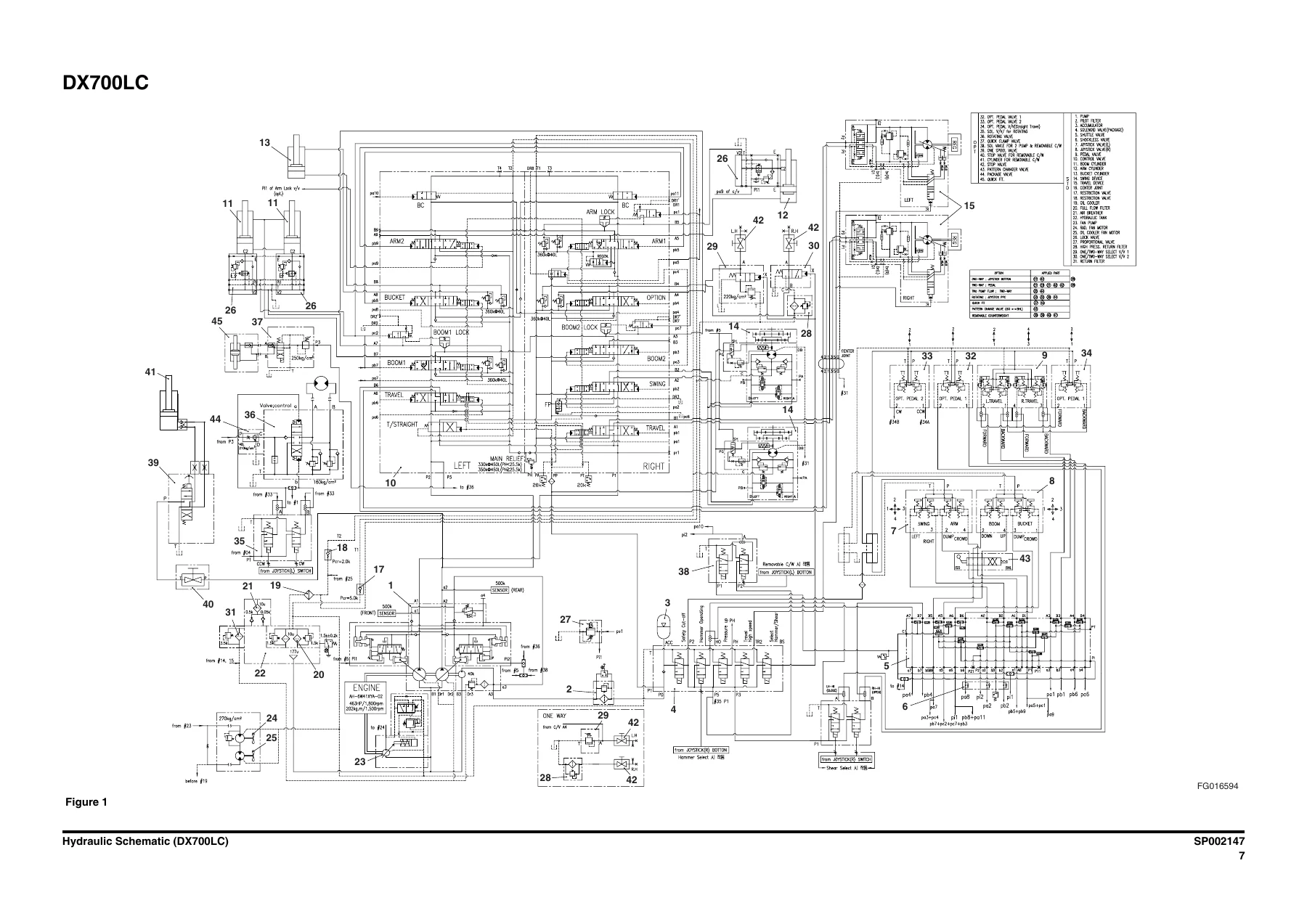
  • Hydraulics – Hydraulic System Troubleshooting Testing and Adjustment, Accumulator, Center Joint (Swivel), Cylinders, Swing Motor, Travel Motor, Travel Reduction Gear, Main Pump, Regulator of Main Pump, Gear Pump for Pilot, Main Control Valve, Remote Control Valve (Work Lever / Joystick), Travel Control Valve (with Damper), Fan Motor, Fan Pump, Solenoid Valve Assembly, Breaker EPPR Valve (Optional), Hydraulic Schematic
  • Electrical System – Electrical Supply System, Engine Starting Circuit, Engine Preheating System, Engine Stop, Charging System, Monitoring System, Instrument Panel, e-EPOS Electronic Hydraulic Control System, Power Mode Control, Engine Control System, Automatic Deceleration Control, Engine Overheat Protection System, Power Boost Mode, Automatic Travel Speed Control, Self-diagnostic Function, Air Conditioner System, Wiper System, Lighting System, Overload Warning Device, Audio Controller, Electrical Schematic
  • Attachments – Boom and Arm, Bucket, Auto Grease System

IMAGES PREVIEW

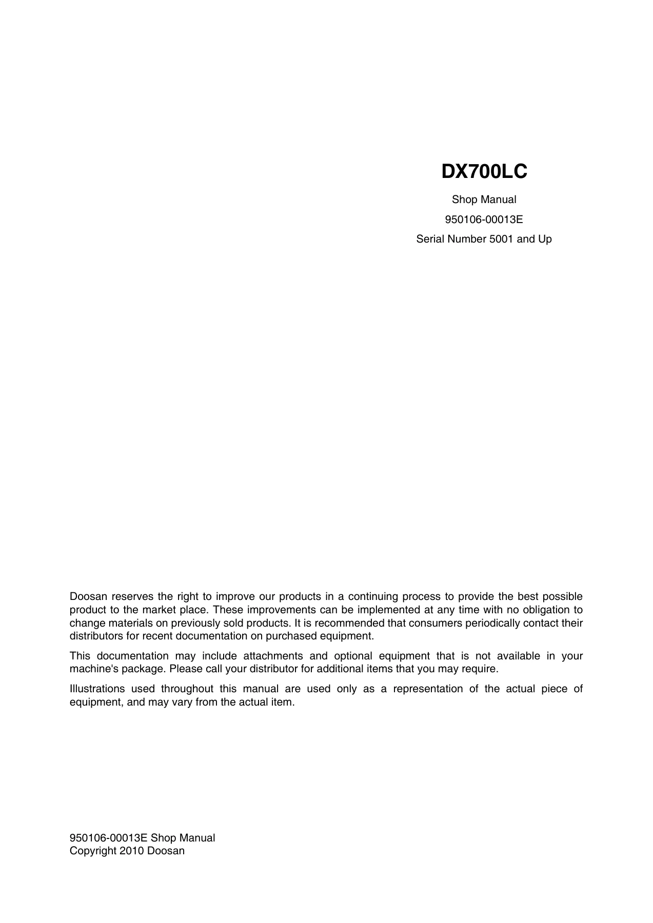
Doosan DX700LC Excavator Shop Manual 950106-00013E 2010 Repair Guide — PDF page 1 preview
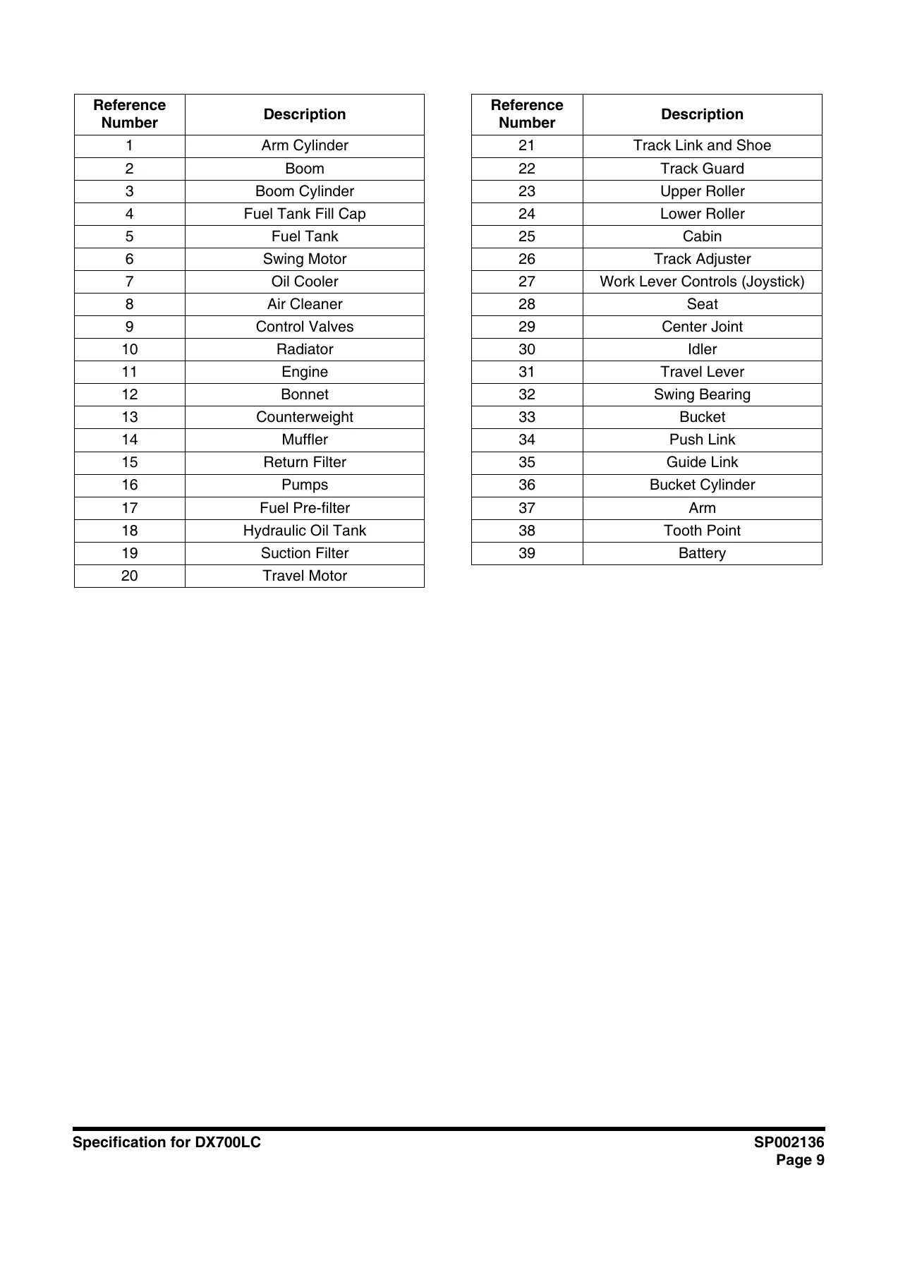
Doosan DX700LC Excavator Shop Manual 950106-00013E 2010 Repair Guide — PDF page 61 preview
Doosan DX700LC Excavator Shop Manual 950106-00013E 2010 Repair Guide — PDF page 997 preview

That chapter list is the skeleton of a full machine teardown. Each SP-numbered section is a standalone service document – SP002261 covers the engine in full, SP002169 covers the K3V280DTH main pump, SP002171 covers the main control valve, SP002181 covers the pump regulator, and SP002140 covers the electrical system. The result is a shop manual that can be used section by section, so a technician working on the hydraulic system does not have to wade through engine overhaul data.

What This Manual Enables

Because the Doosan DX700LC is a large crawler excavator, the range of jobs this manual supports is broad. Engine mechanical work is covered in full: cylinder head removal and disassembly, rocker arm inspection and reassembly, camshaft disassembly and end-play measurement, timing gear and idle gear backlash, flywheel and flywheel housing, piston and connecting rod inspection, crankshaft runout, cylinder block and liner measurement. Cooling system, fuel system, lubrication system and turbocharger each get their own chapter with removal, inspection, reassembly and torque specifications.

The hydraulic section is where a lot of DX700LC work will concentrate. The main pump chapter covers the K3V280DTH twin-pump assembly – disassembly, inspection, reassembly, and the pump main body maintenance standard with wear limits for the piston, shoe thickness, cylinder spring free height and set plate clearance. The regulator chapter explains the KR3D-ZP53-V and KR3D-ZP54-V regulator operation – horsepower control, power shift control, flow control – and provides the adjustment table for maximum flow, minimum flow, input horsepower and flow control attributes.

Control valve work is documented at spool level. The main control valve chapter walks through neutral passages, single operation, combined operation, anti-drift valve operation, main relief valve and overload relief valve function, then covers disassembly and reassembly of the main spools, sub-spools, swing load check, load checks and relief valves, with torque values for every plug and flange. The remote control valve (joystick) and travel control valve (with damper) each have their own procedures.

Cylinder repair is covered in a dedicated chapter – piston and cylinder head assembly, seal ring, buffer ring, U-ring, wiper ring, bushing replacement, torque for piston nut and cylinder head bolts, and the wear limits for piston rod outside diameter, rod bushing inside diameter and piston slide ring thickness.

The swing and travel functions have full motor and reduction gear coverage. The M2X210 swing motor chapter includes the theory of operation, time delay valve, brake section, service limits for piston diameter, cylinder bore, shoe flange thickness and brake friction plate. The travel motor chapter covers the MSF-340VP series with counter balance valve, two-speed change mechanism, parking brake and relief valve operation. The travel reduction gear chapter covers the planetary unit with disassembly, reassembly and final test procedures.

Complete PDF Bookmark Tree

Complete Bookmarks

The complete bookmarks in the “Doosan DX700LC Excavator Shop Manual 950106-00013E 2010 Repair Guide” are as follows:

DX700LCp. 1
Table of Contentsp. 5
Safetyp. 7
Track Excavator Safety SP002135p. 9
Safety Precautionsp. 13
Applicable Modelsp. 13
To the Operator of a DOOSAN Excavatorp. 14
Learn the Signal Words Used with the Safety Alert Symbolp. 16
General Safety Essentialsp. 17
Accessory Applicationsp. 17
Lifting Capacity Rating Configurationp. 17
Location of Safety Labelsp. 18
Summary of Safety Precautions for Lifting in Digging Modep. 18
Unauthorized Modificationsp. 19
General Hazard Informationp. 19
Safety Rulesp. 19
Safety Featuresp. 20
Inside Operator's Compartmentp. 20
Clothing and Personal Protective Itemsp. 21
Breathing Masks, Ear Protection May Be Requiredp. 21
Vibration Level Informationp. 21
Recommendations for Limiting Vibrationsp. 22
Mounting and Dismountingp. 23
Fuel, Oil and Hydraulic Fluid Fire Hazardsp. 23
Precautions When Handling Fluids at High Temperaturep. 24
Asbestos Dust Hazard Preventionp. 24
Injury from Work Equipmentp. 25
Fire Extinguisher and First Aid Kitp. 25
Protection from Falling or Flying Objectsp. 26
Attachment Precautionsp. 26
Accumulatorp. 27
Indoor Ventilationp. 27
Emergency Exitp. 27
Before Starting Enginep. 28
Work Site Precautionsp. 28
Checks Before Starting Enginep. 29
Engine Startingp. 29
Before Operating Machinep. 30
Machine Operationp. 31
When Swinging or Changing Direction of Travelp. 31
Travel Precautionsp. 32
Traveling on Slopesp. 33
Prohibited Operationsp. 34
Precautions for Operationp. 35
Avoid High Voltage Cablesp. 35
Protecting Cabin from Falling Object (Optional)p. 36
Operate Carefully on Snow, Ice and in Very Cold Temperaturesp. 36
Operations on Slopesp. 37
Parking Machinep. 37
Never Let Anyone Ride on Attachmentp. 37
Maintenancep. 38
Warning Tagp. 38
Clean Before Inspection or Maintenancep. 38
Proper Toolsp. 39
Use of Lightingp. 39
Fire Prevention and Explosion Preventionp. 39
Burn Preventionp. 40
Welding Repairsp. 41
Preparation for Electrical Welding on Body Structurep. 42
Warning for Counterweight and Front Attachment Removalp. 42
Precautions for Removal, Installation, and Storage of Attachmentsp. 43
Precautions When Working on Machinep. 43
Lock Inspection Coversp. 43
Crushing Prevention and Cutting Preventionp. 44
Track Tension Adjustments Require Cautionp. 44
Supports and Blocking for Work Equipmentp. 44
Action When Abnormality Is Found During Inspectionp. 45
Precautions with High-pressure Lines, Tubes and Hosesp. 45
Waste Materialsp. 46
Batteryp. 47
Battery Hazard Preventionp. 47
Boost Starting or Charging Engine Batteriesp. 48
Towingp. 49
Precautions When Towingp. 49
Shipping and Transportationp. 50
Obey State and Local Over-the-Road Regulationsp. 50
Lifting With Slingp. 50
Specificationsp. 51
Specification for DX700LC SP002136p. 53
Safety Precautionsp. 57
Applicable Modelsp. 57
General Descriptionp. 59
Component Locationsp. 60
General Dimensionsp. 62
Working Rangep. 63
General Specificationsp. 66
Engine Performance Curves (Per DIN 6270 Standard)p. 68
Approximate Weight of Workload Materialsp. 70
Performance Testsp. 72
Excavator Performance Standardsp. 73
Test Conditionsp. 73
Travel Speed and Travel Motor Balance (Steering Deviation) Testsp. 73
Speed Testp. 73
Travel Deviationp. 75
Swing Speed and Deceleration Force Testp. 75
Swing Speed Testp. 75
Swing Deceleration Force Testp. 76
Cylinder Performance Testsp. 77
Boom Cylinders Testp. 77
Arm Cylinder Testp. 77
Bucket Cylinder Testp. 77
Hydraulic Cylinder Natural Drop Testp. 77
Travel Motor Jack-up Testp. 78
General Maintenancep. 79
General Maintenance Procedures SP000016p. 81
Safety Precautionsp. 85
Applicable Modelsp. 85
Welding Precautions and Guidelinesp. 86
Hydraulic System – General Precautionsp. 87
Maintenance Service and Repair Procedurep. 89
General Precautionsp. 89
Hydraulic System Cleanliness and Oil Leaksp. 90
Maintenance Precautions for Hydraulic System Servicep. 90
Oil Leakage Precautionsp. 91
Cleaning and Inspectionp. 92
General Guidelinesp. 92
Bearing inspectionp. 93
Normal Bearingp. 94
Bent Cagep. 94
Gallingp. 95
Abrasive Step Wearp. 95
Etchingp. 96
Misalignmentp. 96
Indentationsp. 96
Fatigue Spallingp. 97
Brinellingp. 97
Cage Wearp. 97
Abrasive Roller Wearp. 98
Cracked Inner Racep. 98
Smearsp. 98
Frettagep. 99
Heat Discolorationp. 99
Stain Discolorationp. 99
Standard Torques SP000813p. 101
Safety Precautionsp. 105
Applicable Modelsp. 105
Torque Values for Standard Metric Fastenersp. 106
Torque Values for Standard U.S. Fastenersp. 107
Type 8 Phosphate Coated Hardwarep. 109
Torque Values for Hose Clampsp. 110
Torque Values for Split Flangesp. 111
Torque Wrench Extension Toolsp. 112
Torque Multiplicationp. 112
Other Uses for Torque Wrench Extension Toolsp. 113
Tightening Torque Specifications (Metric)p. 114
I. "Loctite" Fastener Adhesivesp. 115
II. "Loctite" Pipe Thread Sealantp. 115
III. "Loctite" gasket/flange sealerp. 115
IV. "Loctite" retaining compoundsp. 116
V. "Loctite" Adhesivesp. 116
Upper Structurep. 117
Cabin SP002148p. 119
Safety Precautionsp. 123
Applicable Modelsp. 123
Removalp. 124
Installationp. 128
Counterweight SP002141p. 131
Safety Precautionsp. 135
Applicable Modelsp. 135
Generalp. 136
Warning for Counterweight and Front Attachment Removalp. 136
Removalp. 138
Installationp. 140
Fuel Tank SP002142p. 143
Safety Precautionsp. 147
Applicable Modelsp. 147
General Descriptionp. 148
Parts Listp. 148
Specificationsp. 149
Removalp. 150
Installationp. 154
Start-up Proceduresp. 157
Fuel Transfer Pump (Opt) SP002143p. 159
Safety Precautionsp. 163
Applicable Modelsp. 163
General Descriptionp. 164
Theory of Operationp. 164
Troubleshootingp. 165
Replacement of Rotor and Vanep. 165
Replacement of Rear Coverp. 166
Replacement of Armaturep. 166
Swing Bearing SP002165p. 167
Safety Precautionsp. 171
Applicable Modelsp. 171
Swing Bearing Maintenancep. 172
Operating Recommendationp. 172
Measuring Swing Bearing Axial Playp. 172
Measuring Bearing Lateral Playp. 172
Swing Bearing Basic Operationp. 173
Rebuilding Swing Bearingp. 173
Swing Reduction Gear SP002149p. 175
Safety Precautionsp. 179
Applicable Modelsp. 179
General Descriptionp. 181
Theory of Operationp. 181
Parts Listp. 182
Specificationsp. 184
Troubleshooting, Testing and Adjustmentp. 185
Removalp. 186
Disassemblyp. 187
Assemblyp. 191
Shaft and S/R Bearing Shrinkage Fittingp. 191
Assembly of the Carrier Subassemblyp. 193
Washing of the Carrierp. 193
Washing of Planet Gearsp. 193
Assembly of the Carrier Subassembly 1p. 193
Assembly of the Carrier Subassembly 2p. 197
Assembly of Main Casep. 201
Washing of the Casing and Other Componentsp. 201
Assembly of the Shaft and the Pinionp. 201
Assembly of the Seal and the Bearingp. 206
Assembly of the Ring Gearp. 210
Assembly of the Carrierp. 212
Testp. 217
Pneumatic Testp. 217
Noise and Abnormal Sound Testp. 218
Assembly of the Motorp. 219
Supply of Gear Oilp. 219
Assembly of the Motorp. 220
Installationp. 225
Start-up Proceduresp. 225
Lower Structure and Chassisp. 227
Track Assembly SP002146p. 229
Safety Precautionsp. 233
Applicable Modelsp. 233
General Descriptionp. 234
Track Tensionp. 234
Cleaning and Inspection (Wear Limits and Tolerances)p. 237
Track Shoep. 238
Lower Rollerp. 240
Lower Roller Disassemblyp. 241
Lower Roller Disassembly or Reassembly Toolp. 241
Upper Rollerp. 243
Upper Roller Disassemblyp. 244
Upper Roller Disassembly or Reassembly Toolp. 244
Front Idlerp. 246
Track Shoes and Linksp. 247
Track Removalp. 247
Track Installationp. 248
Front Idler Rollerp. 249
Parts Listp. 249
Front Idler Roller Disassemblyp. 250
Front Idler Roller Reassemblyp. 251
Lower Rollerp. 253
Parts Listp. 253
Lower Roller Removalp. 254
Lower Roller Disassemblyp. 254
Lower Roller Reassemblyp. 255
Lower Roller Installationp. 256
Upper Rollerp. 257
Parts Listp. 257
Upper Roller Removalp. 258
Upper Roller Disassemblyp. 258
Upper Roller Reassemblyp. 260
Track Spring and Track Adjusting Cylinderp. 261
Under Carrige Track Springp. 262
Track Spring Assembly Diagramp. 262
Track Spring Disassembly Diagramp. 263
Disassembly of the Track Spring Assemblyp. 264
Assembly of the Track Springp. 266
Sprocket, Measurement of Wearp. 268
Measuring of Tooth Profilep. 269
Measuring of Tooth Widthp. 269
Guide Measurement Paper of Tooth Profilep. 271
Engine and Drive Trainp. 273
Engine SP002261p. 275
Safety Precautionsp. 279
Applicable Modelsp. 279
General Informationp. 281
Service Precautionsp. 281
In Order to Carry Out Work Safelyp. 281
Replacement Parts and Part Numbersp. 282
Liquid Gasketp. 283
Procedure for Using the Plastigaugep. 286
Reading the Modelp. 288
Engine Number Stamping Positionp. 288
General Informationp. 289
Terminology, Description of Abbreviationsp. 289
SI (International System of Units)p. 291
Table of Isuzu Standard Tightening Torquep. 293
Special Tool Classificationp. 296
Engine Mechanicalp. 297
ISUZU Diesel Enginep. 297
Service Precautionsp. 297
Explanations on Functions and Operationp. 299
Function Checkp. 301
Specificationsp. 306
Engine Accessoriesp. 307
Componentsp. 307
Removalp. 308
Installationp. 309
Engine Exterior Equipmentp. 311
Componentsp. 311
Removalp. 314
Inspectionp. 325
Installationp. 326
Torque Specificationsp. 341
Cylinder Headp. 343
Componentsp. 343
Removalp. 344
Disassemblyp. 348
Inspectionp. 351
Reassemblyp. 355
Installationp. 362
Torque Specificationsp. 370
Rocker Armp. 371
Componentsp. 371
Disassemblyp. 372
Inspectionp. 372
Reassemblyp. 374
Camshaftp. 375
Componentsp. 375
Disassemblyp. 375
Inspectionp. 376
Reassemblyp. 378
Torque Specificationsp. 378
Timing Gearp. 379
Componentsp. 379
Removalp. 380
Disassemblyp. 381
Inspectionp. 382
Reassemblyp. 383
Installationp. 384
Torque Specificationsp. 388
Flywheel, Flywheel Housingp. 389
Componentsp. 389
Removalp. 390
Disassemblyp. 391
Inspectionp. 391
Reassemblyp. 391
Installationp. 392
Torque Specificationsp. 394
Piston, Connecting Rodp. 395
Componentsp. 395
Removalp. 396
Disassemblyp. 397
Inspectionp. 398
Reassemblyp. 402
Installationp. 404
Torque Specificationsp. 406
Crankshaftp. 407
Componentsp. 407
Removalp. 408
Disassemblyp. 409
Inspectionp. 409
Reassemblyp. 413
Installationp. 413
Cylinder Blockp. 415
Componentsp. 415
Disassemblyp. 415
Inspectionp. 416
Reassemblyp. 417
Torque Specificationsp. 420
Special Toolp. 421
List of Special Toolp. 421
Cooling Systemp. 422
Service Precautionsp. 422
Explanations on Functions and Operationp. 422
List of Trouble Symptomp. 425
Specificationsp. 425
Thermostatp. 426
Componentsp. 426
Removalp. 427
Inspectionp. 427
Installationp. 428
Torque Specificationsp. 428
Water Pumpp. 429
Componentsp. 429
Disassemblyp. 430
Inspectionp. 431
Reassemblyp. 431
Torque Specificationsp. 434
Special Toolp. 434
List of Special Toolp. 434
Fuel Systemp. 435
Fuel Systemp. 435
Service Precautionsp. 435
Explanations on Functions and Operationp. 436
Function Checkp. 439
Specificationsp. 440
Fuel Filterp. 441
Componentsp. 441
Disassemblyp. 442
Inspectionp. 443
Reassemblyp. 444
Special Toolp. 446
List of Special Toolp. 446
Electrical Systemp. 447
Starting Systemp. 447
Service Precautionsp. 447
Explanations on Functions and Operationp. 447
List of Trouble Symptomp. 448
Specificationsp. 449
Starterp. 450
Componentsp. 450
Disassemblyp. 451
Inspectionp. 455
Reassemblyp. 458
No Load Testp. 460
Maintenance Standardp. 461
Torque Specificationsp. 461
Charging Systemp. 462
Service Precautionsp. 462
Explanations on Functions and Operationp. 463
Charging Circuitp. 464
Structurep. 464
List of Trouble Symptomp. 465
Specificationsp. 465
Generatorp. 466
Componentsp. 466
Disassemblyp. 468
Inspectionp. 470
Reassemblyp. 472
Bench Testp. 473
Maintenance Standardp. 474
Torque Specificationsp. 475
Lubricating Systemp. 476
Lubrication Systemp. 476
Service Precautionsp. 476
Explanations on Functions and Operationp. 476
Specificationsp. 479
Maintenance Standardp. 479
Oil Filterp. 480
Componentsp. 480
Disassemblyp. 481
Reassemblyp. 481
Oil Pan, Oil Jetp. 482
Componentsp. 482
Removalp. 483
Installationp. 483
Torque Specificationsp. 486
Oil Pumpp. 487
Componentsp. 487
Disassemblyp. 488
Inspectionp. 488
Reassemblyp. 490
Torque Specificationsp. 491
Oil Coolerp. 492
Componentsp. 492
Disassemblyp. 493
Inspectionp. 494
Reassemblyp. 494
Torque Specificationsp. 496
Special Toolp. 496
List of Special Toolp. 496
Intake systemp. 497
Turbocharger Systemp. 497
Service Precautionsp. 497
Explanations on Functions and Operationp. 497
List of Trouble Symptomp. 498
Maintenance Standardp. 498
Turbochargerp. 499
Componentsp. 499
Disassemblyp. 500
Inspectionp. 504
Maintenance Standardp. 507
Reassemblyp. 508
Preheating Systemp. 514
Service Precautionsp. 514
Explanations on Functions and Operationp. 514
Function Checkp. 514
List of Trouble Symptomp. 516
Specificationsp. 516
Drive Coupling (Main Pump) SP000026p. 517
Safety Precautionsp. 521
Applicable Modelsp. 521
Drive Couplingp. 522
Installation of Drive Couplingp. 523
Installation Procedurep. 523
Hydraulicsp. 525
Hydraulic System Troubleshooting, Testing and Adjustment SP002166p. 527
Safety Precautionsp. 531
Applicable Modelsp. 531
Hydraulic System – General Notesp. 532
Hydraulic Schematicp. 533
General Notesp. 533
Operation of Working Componentsp. 535
Boom Operating Circuitp. 535
Boom Up Circuitp. 535
Boom Down Circuitp. 535
Arm Operating Circuitp. 536
Arm Crowd Circuitp. 536
Arm Dump Circuitp. 536
Bucket Operating Circuitp. 537
Bucket Crowd Circuitp. 537
Bucket Dump Circuitp. 537
Swing Operating Circuitp. 538
Right Swing Operating Circuitp. 538
Left Swing Operating Circuitp. 538
Swing Relief Valve and Makeup Valvep. 538
Travel Operating Circuitp. 539
Forward Travel Circuitp. 539
Reverse Travel Circuitp. 539
Procedural Troubleshooting Baseline Recommendationsp. 540
Initial Checks and Tests to Establish Operating Condition of the Excavatorp. 540
Triage Summaryp. 540
Pilot Pressurep. 542
Adjustment and Testingp. 542
Power Mode Valvep. 543
Current Signal and Hydraulic Pressure Adjustmentsp. 543
Pressure Up Valvep. 545
Checks and Adjustmentsp. 545
Pump Input Power Controlp. 547
Pump Regulator Adjustmentp. 547
Flow Meter and Flow Meter Kit Installation and Testingp. 550
Installation and Testing Procedurep. 550
Swing System Troubleshootingp. 552
Precautions/Initial Checksp. 552
Swing Relief Valve Checking and Adjustmentp. 553
Troubleshooting – Swing Gearboxp. 555
Troubleshooting – Hydraulic Problemsp. 557
Troubleshooting – Control Valvep. 559
Troubleshooting – Travel Control Valvep. 560
Troubleshooting – Joystick Control Valvep. 560
Accumulator SP000028p. 561
Safety Precautionsp. 565
Applicable Modelsp. 565
General Descriptionp. 566
Specificationsp. 568
Center Joint (Swivel) SP002167p. 569
Safety Precautionsp. 573
Applicable Modelsp. 573
General Descriptionp. 574
Center Joint Disassembly Diagramp. 575
Disassemblyp. 576
Reassemblyp. 579
Cylinders SP002137p. 583
Safety Precautionsp. 587
Applicable Modelsp. 587
Specification and Assembly Drawingp. 588
Arm cylinderp. 589
Boom cylinderp. 590
Functionp. 591
Basic Functionp. 591
Function of Each Partp. 591
Theory of Cylinder Functionp. 595
Important Precautionp. 598
Precautions when Installing and Removing Cylinderp. 598
Precautions in Usep. 599
Precautions in Inspection and Maintenancep. 600
Inspection and Maintenancep. 601
Troubleshootingp. 602
Storage Standardp. 606
Cylinder Storage by Itself (The cylinder must be kept indoors.)p. 606
Cylinder Storage with Machinep. 607
Recommended Rust Preventive Oilp. 607
Instruction of Disassembly and Assemblyp. 608
Preparationp. 608
General Precautionsp. 608
Maintenance Standardp. 608
Test after Assemblyp. 609
Toolp. 610
Instruction of Disassemblyp. 614
Instruction of Assemblyp. 619
Test Operationp. 625
Wear Limitp. 625
Swing Motor SP002168p. 627
Safety Precautionsp. 631
Applicable Modelsp. 631
Instruction Manualp. 632
Indication of Typep. 632
Specificationsp. 633
Construction and Working Principlep. 634
Constructionp. 634
Parts Listp. 635
Principles of Workingp. 636
General Handling Methodp. 640
Inspectionp. 640
Rotating Directionp. 640
External Load on Shaft Endp. 641
Filterp. 643
Installation and Pipingp. 643
Oil Filling and Air Ventingp. 643
Cautions in Starting Operationp. 644
Causes of Troubles and Countermeasuresp. 644
General Precautionsp. 644
Check of Motor for Abnormalitiesp. 645
Causes of Troubles and Remediesp. 646
Maintenancep. 648
Service Limitp. 648
Renovation Limitp. 651
Performance Test Procedure and Acceptance Standardp. 651
Scope Appliedp. 651
Operating Conditionp. 651
Preliminary Operationp. 651
Test Detailsp. 652
Performance Testp. 652
Shaft Creep Speed (Clockwise and Counterclockwise)p. 653
Starting Testp. 653
Braking Torque Testp. 653
Time Delay Valve Performance Testp. 653
Travel Motor SP002145p. 655
Safety Precautionsp. 659
Applicable Modelsp. 659
Instruction Manualp. 660
Introuductionp. 660
Outlinep. 660
Structure of Traveling Motorp. 660
Featuresp. 660
Indication of Typep. 661
Specificationsp. 661
Structure and Functionp. 662
Working Principle of Swash Plate Type Axial Piston Motorp. 665
Working Principle of Counter Balance Valvep. 666
Function of Counter Balance Valve (Counter Balance Valve work)p. 667
Function of Counter Balance Valve (Brake Work)p. 669
Working Principle of Two-Speed Change Mechanismp. 670
When running at 1st speed (low speed)p. 670
When running at 2nd speed (high speed)p. 671
Working Principle of Auto Two Speed Change Mechanismp. 672
Working Principle of Relief Valvep. 674
Working Principle of Parking Brakep. 675
Precautions and Warningsp. 676
Inspectionp. 676
Direction of Rotationp. 676
Hydraulic Fluidp. 676
Filtersp. 677
Piping Workp. 677
Cautions in Using Parking Brakep. 678
Operating Steps and Precautionsp. 678
Precautions at Startupp. 678
Hydraulic Fluid Temperature during Operationp. 678
Periodic Inspection and Criteria of Oil Changep. 679
Hydraulic Fluidp. 679
Filtersp. 679
Troubleshootingp. 680
Piston Motorp. 680
Counter Balance Valvep. 681
Relief Valvep. 683
Two Speed Control Valvep. 684
Parking Brakep. 684
Maintenance Instructionp. 685
Tools for Disassembly and Reassemblyp. 685
Disassemblyp. 686
General Instructionsp. 686
Disassembling Procedurep. 686
Maintenance Manualp. 692
Reassemblyp. 695
General Instructionsp. 695
Reassembling Procedurep. 696
Quality Check After Reassemblyp. 704
Travel Reduction Gear SP002144p. 705
Safety Precautionsp. 709
Applicable Modelsp. 709
General Informationsp. 711
Safety Informationsp. 711
Lifting and Handlingp. 712
Storagep. 713
Technical Informationsp. 714
Product Descriptionp. 714
Installation Informationsp. 716
Installation Procedurep. 716
Hydraulic Motor Installationp. 716
Installation of the Track Drive on the Machinep. 717
Gearbox Lubricationp. 718
First start up and Running inp. 720
Maintenance Informationsp. 721
Periodic Maintenancep. 721
Oil Draining and Replacementp. 722
Trouble Shootingsp. 723
Disassemblyp. 724
Special Toolsp. 724
Gearbox Disassemblyp. 726
Evaluating that Pieces to Replacep. 736
Gearbox Reassemblyp. 736
Make Ready of the Lifetime Seal:p. 740
Final Test and Reinstallationp. 749
Dismantling and Destroying the Productp. 749
Main Pump SP002169p. 751
Safety Precautionsp. 755
Applicable Modelsp. 755
Axial Piston Pumpp. 757
General Descriptionp. 757
Model Number Designationp. 757
Theory of Operationp. 758
Parts Listp. 760
Torquesp. 762
Special Tools and Materialsp. 763
Toolsp. 763
Troubleshooting, Testing and Adjustmentp. 765
Disassemblyp. 767
Assemblyp. 770
Pump Main Body Maintenance Standardp. 773
Replacement of Consumable Partsp. 773
Guideline for Correction of Cylinder, Valve Plate and Swash Plate (Shoe Plate)p. 774
Tightening Torquep. 774
Regulator of Main Pump SP002181p. 775
Safety Precautionsp. 779
Applicable Modelsp. 779
Naming Conventionp. 780
Specificationsp. 781
Overviewp. 781
Operation Descriptionp. 782
Flow Controlp. 782
Flow Increase Operation (Ref. Figure 1)p. 782
Flow Decrease Operation (Figure 1)p. 782
Horsepower Controlp. 783
Prevention of Overloading (Figure 2)p. 783
Flow Recovery Operationp. 784
Mechanism for Prioritized Low Swivel Angle (Low Flow) Controlp. 784
Power Shift Control (Reducing Horsepower Control)p. 785
Regulator Adjustmentp. 785
Adjustment of Maximum Flow (Pump Main Body)p. 785
Adjustment of Minimum Flow (Pump Main Body)p. 785
Adjustment of Input Horsepowerp. 786
Adjustment of Outer Springp. 786
Adjust of Inner Springp. 786
Adjustment of Flow Control Attributep. 786
Regulator Troubleshootingp. 787
Motor Overloadp. 787
Maximum Flow Not Obtainedp. 787
Regulator Adjustment Tablep. 787
Flow Rate Decreasep. 788
Flow Rate Decreasep. 789
Flow Rate Recoveryp. 790
Overload Preventionp. 791
Part List – Frontp. 792
Part List – Rearp. 794
Gear Pump for Pilot SP000033p. 797
Safety Precautionsp. 801
Applicable Modelsp. 801
Single Gear Pumpp. 802
Disassemblyp. 802
Reassemblyp. 804
Double Gear Pumpp. 808
Disassemblyp. 808
Reassemblyp. 810
Main Control Valve SP002171p. 815
Safety Precautionsp. 819
Applicable Modelsp. 819
General Descriptionp. 821
When All Spools are in Neutralp. 821
Neutral Passage (Figure 1 and Figure 2)p. 821
Signal Passage (Figure 2)p. 822
Single Operationp. 824
Travel Spool Shifting (Figure 3 and Figure 4)p. 824
Swing Spool Shifting (Figure 4)p. 826
Boom Spool Shiftingp. 827
Spare Spool Shifting (Figure 8)p. 830
Bucket Spool Shifting (Figure 8)p. 830
Arm Spool Shiftingp. 831
Neutral-cut Spool Shifting (Figure 11)p. 834
Parallel Throttle for Arm (Figure 11)p. 834
Relief Valvep. 835
Combined Operationp. 836
Travel Combined Operation (Figure 13)p. 836
Swing Combined Operation (Figure 14)p. 838
Anti Drift Valvep. 839
Main Relief Valvep. 839
Overload Relief Valvep. 840
Parts Listp. 842
Spool Assembly (4, Bucket)p. 845
Spool Assembly (5, Boom)p. 845
Spool Assembly (6, Travel)p. 845
Spool Assembly (7, Straight Travel)p. 846
Spool Assembly (8, Arm1)p. 846
Spool Assembly (9, Service)p. 846
Spool Assembly (10, Boom 2)p. 847
Spool Assembly (11, Swing)p. 847
Spool Assembly (3, Arm 2)p. 847
Spool Assembly (20, Arm Regeneration Release Valvep. 847
Spool Assembly (24)p. 848
Poppet Assembly (36)p. 848
Plug Assembly (51)p. 848
Plug Assembly (58)p. 848
Relief Valve Assembly (48)p. 849
Relief Valve Assembly (49)p. 849
Troubleshooting, Testing and Adjustmentp. 850
Generalp. 850
Relief Valvep. 851
Hydraulic Systemp. 851
Adjustment of Relief Valvep. 851
Main Relief Valvep. 851
Over Load Relief Valvep. 852
Disassemblyp. 853
General Instructions for Disassemblyp. 853
Disassembly of Main Spool (3) – (11)p. 853
Disassembly of Subspool (24)p. 854
Disassembly of Subspool (20)p. 854
Disassembly of Anti Drift Valve of Boom and Armp. 855
Disassembly of Swing Load Checkp. 855
Disassembly of Load Checkp. 856
Disassembly of Other Check Valvesp. 856
Disassembly Of Flangep. 856
Disassembly of Relief Valvep. 857
Disassembly of Other Flangep. 857
Disassembly of Main Relief Valvep. 858
Disassembly of Overload Relief Valvep. 859
Disassembly of Low Pressure Relief Valvep. 859
Cleaning and Inspection (Wear Limits and Tolerances)p. 860
Cleaningp. 860
Inspectionp. 860
Reassemblyp. 861
Subassemblyp. 861
Main Spool (3) – (11)p. 861
Subspool (20)p. 861
Subspool (24)p. 862
Boom, Arm Anti Drift Valvep. 862
Swing Load Checkp. 862
Reassembly of Control Valvep. 862
Reassembly of Load Check Valvep. 862
Reassembly of Swing Load Checkp. 863
Reassembly of Other Check Valvep. 863
Reassembly of Flangep. 864
Reassembly of Boom and Arm Anti Drift Valvep. 864
Reassembly of Relief Valvep. 864
Reassembly of Subspool (24)p. 864
Reassembly of Subspool (20)p. 865
Reassembly of Main Spool (3) – (11)p. 865
Reassembly of Other Plugsp. 865
Reassembly of Main Relief Valvep. 866
Reassembly of Overload Relief Valvep. 867
Installationp. 868
Start-up Proceduresp. 868
Remote Control Valve (Work Lever / Joystick) SP002174p. 869
Safety Precautionsp. 873
Applicable Modelsp. 873
Safety Cautionp. 875
Notes on the Operation Manualp. 875
Safety Cautionp. 875
Product Operating Cautionsp. 876
Product Handling Cautionp. 877
Product Assembly and Disassembly Cautionsp. 877
Maintenance Cautionp. 878
Performance Cautionp. 878
Immunity from Responsibilityp. 879
Overviewp. 879
Specificationsp. 880
Structurep. 880
Functionsp. 881
Basic Functionsp. 881
Functions of the Main Partsp. 881
Operationp. 882
Handle in Neutral (Figure 2)p. 882
Handle Inclined (Figure 3)p. 883
Handle Inclined (Figure 4)p. 883
Operation at a High Handle Inclination (Depending on the Form)p. 883
Maintenance Guidelinep. 884
Necessary Tools and Tightening Torquep. 884
Maintenance Standardp. 885
Disassembly Procedurep. 886
Preparationp. 886
General Cautionp. 886
Disassembly Procedurep. 886
Assembly Procedurep. 891
Preparationp. 891
General Cautionp. 891
Assembly Procedurep. 892
Troubleshootingp. 896
Parts Listp. 897
Travel Control Valve (with Damper) SP002172p. 899
Safety Precautionsp. 903
Applicable Modelsp. 903
General Descriptionp. 905
Theory of Operationp. 905
Pressure Reducing Valvep. 906
Operating Theory of Damper Mechanismp. 907
Causes of Faults and Measuresp. 909
Parts Listp. 910
Specificationp. 912
Torquesp. 912
Removalp. 913
Disassemblyp. 914
Cleaning and Inspection (Wear Limits and Tolerances)p. 916
Reassemblyp. 917
Installationp. 922
Start-up Proceduresp. 923
Fan Motor (Fan Cooling Drive) SP002175p. 925
Safety Precautionsp. 929
Applicable Modelsp. 929
Disassembling Fan Motorp. 931
Reassembling Fan Motorp. 938
Fan Pump (Fan Cooling Drive) SP002176p. 943
Safety Precautionsp. 947
Applicable Modelsp. 947
Disassembling Fan Pumpp. 949
Reassembling Fan Pumpp. 955
Solenoid Valve Assembly SP001622p. 961
Safety Precautionsp. 965
Applicable Modelsp. 965
5-Solenoid Valvep. 966
Parts Listp. 966
Functions of 5-Solenoid Valve Assemblyp. 967
Functions and Operations of Solenoid Valvesp. 967
Detailed Functions and Operations of Solenoid Valvesp. 967
Assembly Diagram and Tools Requiredp. 970
Cautions During Disassembly and Reassemblyp. 971
Solenoid Valve Diagramp. 972
Check Points and Solutions for Problemsp. 973
Checking of Pilot Pressure for Defectsp. 973
2-Solenoid Valvep. 974
Parts Listp. 974
Assembly Diagram and Tools Requiredp. 975
Cautions During Disassembly and Reassemblyp. 976
Solenoid Valve Diagramp. 977
Troubleshooting Guidep. 977
Breaker EPPR Valve (Opt) SP000192p. 979
Safety Precautionsp. 983
Applicable Modelsp. 983
Structurep. 984
Numbers and Names of Partsp. 984
Functions and Operationp. 985
Cautions for Operationp. 985
Maintenance Instructionsp. 986
Maintenancep. 986
Bolt Tightening Torquep. 986
Tools Used for Disassembly and Assemblyp. 986
Disassemblyp. 987
Assemblyp. 988
Hydraulic Schematic (DX700LC) SP002147p. 991
Safety Precautionsp. 995
Applicable Modelsp. 995
DX700LCp. 997
Electrical Systemp. 999
Electrical System SP002140p. 1001
Safety Precautionsp. 1005
Applicable Modelsp. 1005
Introductionp. 1007
Electrical Supply Systemp. 1008
Engine Starting Circuitp. 1010
Start Operationp. 1010
After Startp. 1012
Engine Preheating Systemp. 1014
Engine Stopp. 1016
Charging Systemp. 1018
Monitoring Systemp. 1019
Instrument Panelp. 1020
Monitoring System Schematicp. 1022
Operationp. 1024
Instrumentsp. 1024
Warning and Indicator Lightsp. 1026
Indication of Warning Lightsp. 1026
Indication of Multifunction Gaugep. 1027
Initial Operationp. 1029
Mode Selector Switchp. 1030
Graphic Information Area Displayp. 1032
Overviewp. 1032
Main Menus for the Graphic Display Areap. 1033
Menu Selector Buttonsp. 1033
Main Menup. 1034
Languagep. 1034
Set Clockp. 1035
Filter/Oil Infop. 1035
Adjust Displayp. 1036
Set Passwordp. 1037
Special Menup. 1038
Entering/Accessing and Exiting/Escaping Menusp. 1038
Special Menu Selectionsp. 1039
Electronic Hydraulic Control System (e-EPOS)p. 1054
Control System Schematicp. 1054
Power Mode Controlp. 1056
Operationp. 1058
Power / Economy Mode Control – Circuit Diagramp. 1062
Engine Control Systemp. 1064
Engine Control Dialp. 1065
Engine Control Circuit Diagramp. 1066
Automatic Deceleration Control (Auto Idle Control)p. 1068
Engine Overheat Protection Systemp. 1070
Power Boost Modep. 1072
Operationp. 1072
Power Boost Control – Circuit Diagramp. 1074
Automatic Travel Speed Controlp. 1075
Automatic Travel Speed Control – Circuit Diagramp. 1077
Self-diagnostic Functionp. 1078
e-EPOS Controllerp. 1078
Air Conditioner Systemp. 1080
Outlinep. 1080
Internal and External Filtersp. 1081
Air-Conditioning System Layoutp. 1083
Air Conditioner/heater Circuit Diagramp. 1084
Air Conditioner/heater Unitp. 1085
Ambient Air Temperature Sensorp. 1090
Sun Sensorp. 1091
Control Panelp. 1091
Compressorp. 1098
Receiver Dryerp. 1098
Troubleshootingp. 1099
Weight of R134a Gas Used In Machinesp. 1101
Refrigerant System Repairsp. 1102
Refrigerant Safe Handling Proceduresp. 1102
Repair and Replacement Procedurep. 1104
Refrigerant Recoveryp. 1106
Vacuuming Refrigerant Systemp. 1106
Leakage Checkp. 1108
Refrigerant Chargingp. 1108
Inspecting System For Leakagep. 1110
Wiper Systemp. 1111
Wiper Circuitp. 1111
Wiper operationp. 1112
Lighting Systemp. 1114
Lighting System Circuit Diagramp. 1114
Kind of Lightp. 1115
Operationp. 1115
Overload Warning Devicep. 1116
Overload Warning Device Circuit Diagramp. 1116
Audio Controllerp. 1117
Audio Controller Circuit Diagramp. 1117
Electrical Schematic (DX700LC) SP002189p. 1119
Safety Precautionsp. 1123
Applicable Modelsp. 1123
DX700LCp. 1125
Attachmentsp. 1127
Boom and Arm SP002138p. 1129
Safety Precautionsp. 1133
Applicable Modelsp. 1133
Front Attachment Pin Specificationsp. 1134
Front Attachment – Removal and Installationp. 1136
Arm Removal Procedurep. 1136
Boom Removal Procedurep. 1138
Installationp. 1139
Arm Installation Procedurep. 1139
Boom Installation Procedurep. 1139
Start-up Proceduresp. 1140
Bucket SP002139p. 1141
Safety Precautionsp. 1145
Applicable Modelsp. 1145
Bucket Tooth Inspection and Replacementp. 1146
Bucket O-ring Replacementp. 1147
Bucket Shimming Proceduresp. 1149
New Bucket Installationp. 1149
Shimming Procedures for Installed Bucketp. 1150
Bucket Attachment, Removal and Reversalp. 1151
Detaching the Bucketp. 1151
Attaching the Bucketp. 1152
Reversing the Bucketp. 1152
Auto Grease System SP002216p. 1153
Safety Precautionsp. 1157
Applicable Modelsp. 1157
Pumpp. 1158
Operation, Maintenance and Repairp. 1158
Descriptionp. 1159
The Central Lubrication Pumpp. 1159
Mode of Operationp. 1160
Pump Elements with Fixed Lubricant Outputp. 1160
Check Valvep. 1161
Arrangement of the Pump Elementsp. 1161
Pressure Relief Valvep. 1161
Maintenance, Repair and Testsp. 1162
Maintenancep. 1162
Pump Fillingp. 1162
Repairp. 1163
Pumpp. 1163
Replace Pump Elementp. 1163
Testsp. 1164
Operational Test/triggering an Additional Lubrication Cyclep. 1164
To Check the Safety Valvep. 1164
Troubleshootingp. 1165
Fault: The pump motor does not runp. 1165
Fault: The pump does not deliver the lubricantp. 1165
Time Settingp. 1166
To Set the Pause Timep. 1166
Factory Settingp. 1166
To Set the Operating Timep. 1167
Factory Settingp. 1167
Operational Test/to Trigger an Additional Lubrication Cyclep. 1168
Connection Diagram – Industrial Applications, Printed Circuit Board 236-13891-1 (V10 – V13)p. 1169
Attention! If a pump model 103 CS…E2 is replaced by a pump model P203-…-…-2A1.10, the lamp connection of the illuminated pushbutton must be changed from minus to plus.p. 1170
Metering Devices for Grease and Oil – Model SSVp. 1171
Progressive Metering Devices Model SSV and SSV Mp. 1171
Progressive Plunger Metering Devices – Generalp. 1171
Features of a Progressive Metering Devicep. 1172
Applicationsp. 1172
Lubricant Distribution Within the metering Devicep. 1174
Phase 1p. 1174
Phase 2p. 1174
Phase 3p. 1175
Phase 4p. 1175
Phase 5p. 1175
Determining the Lubricant Output by Combining Outletsp. 1176
Tube Fittings, Screw-Typep. 1176
Instructions for Progressive Systemsp. 1178
Troubleshootingp. 1179
Fault: Blockage in the downstream progressive systemp. 1179
Fault: Differing lubricant amounts at the lubrication pointsp. 1180
Fault: Over or underlubrication of the lubrication pointsp. 1180
Technical Datap. 1181
Dimensionsp. 1181
Lubricantsp. 1182
Recommended grease for systems down to -25°Cp. 1182
Biodegradablep. 1182
Metering Devices for Grease and Oil – Model UVp. 1183
Specificationsp. 1183
Descriptionp. 1183
UV Valve Blocksp. 1184
UV Baseplatesp. 1184
Cycle Indicator Pin Optionp. 1185
Assembly Instructionsp. 1185
Operationp. 1185
Dimensionsp. 1188
Accessoriesp. 1188
Typical Accessory Installationp. 1189

Electrical coverage is extensive. The electrical system chapter documents the 24V supply, engine starting circuit, preheating, charging, monitoring system, the e-EPOS electronic hydraulic control system with power mode and economy mode control, engine control dial, automatic deceleration, engine overheat protection, power boost, automatic travel speed control, and the self-diagnostic function with failure codes. The air conditioner, wiper, lighting, overload warning and audio systems have their own procedures.

Specifications and Service Data

Throughout the Doosan DX700LC Shop Manual, every procedure is backed by the numbers needed to complete it correctly. Torque values for standard metric and U.S. fasteners, Type 8 phosphate coated hardware, hose clamps and split flanges. Maintenance standards for the engine – valve clearance, compression pressure, cylinder liner bore, crankshaft runout, camshaft runout, piston ring end gap and connecting rod bearing clearance. Hydraulic pressures – main relief at 320 kg/cm2 normal and 350 kg/cm2 pressure up, pilot pressure 40 +/- 5 bar, swing relief 300 kg/cm2, and the pressure settings used across the various control valves. Actuator speeds for boom, arm, bucket, swing and travel, plus the natural drop test limits.

Machine specifications are also included – shipping weight, operating weight, major component weights, digging forces, fuel tank capacity 900 liters, hydraulic system capacity 790 liters, hydraulic reservoir capacity 350 liters, and the working range dimensions for the standard boom and arm combinations.

Who This Manual Is For

This Doosan DX700LC Shop Manual is written for the technician who is going to actually take the machine apart. The procedures assume the reader has a workshop, lifting equipment, hand tools and the special tools called out where required. It is not a simplified owner’s guide – it is the full service documentation set, with disassembly and reassembly sequences, inspection criteria, wear limits, torque values and test procedures for each system.

Independent repair shops, fleet maintenance departments, and owner-operators who do their own servicing will all find the section-level structure useful. Because each SP-numbered document is a complete service guide for its component, the Doosan DX700LC Shop Manual works both as a full reference and as a quick lookup when only one system needs attention.

Instant PDF Delivery

The Doosan DX700LC Shop Manual is delivered as an instant PDF download – no shipping, no waiting for a physical book. Once payment is complete the file is available for download and can be viewed on a laptop, tablet or phone in the workshop, or printed for the pages you need at the machine. Having the full Doosan DX700LC Shop Manual on hand means the correct specification and procedure are always within reach, and the job gets done to the standard the machine was built for.

Reviews

There are no reviews yet.

Be the first to review “Doosan DX700LC Excavator Shop Manual 950106-00013E 2010 Repair Guide”

What Our Customers Say

★★★★★ Live reviews from customers
Loading customer reviews...
0
    0
    Your Cart
    Your cart is emptyReturn to Shop
    🛒
    Recently Purchased
    🕒 verified order