
Isuzu C&E Series Cab and Chassis Electrical Workshop Manual 2006+ (LHD) – PDF
Original price was: $39.95.$23.95Current price is: $23.95.
Complete Isuzu C&E Series cab and chassis electrical workshop manual for left hand drive models from 2006 onward. Covers the 24-volt negative ground system, fuse and fusible link identification, relay and diode data, connector service, and full system repair with circuit diagrams for every cab and chassis circuit.
Description
Isuzu C&E Series Cab and Chassis Electrical Workshop Manual – Left Hand Drive Models
This is the Isuzu C&E Series Cab and Chassis Electrical Workshop Manual, Section 9D, written for left hand drive models from the 2006 year model onward. It is the electrical section of the C&E Series workshop manual series, published under document number HGCEL-WE-0662LH in April 2006. Everything inside deals with one subject only: the cab and chassis electrical system of these trucks, from the battery cables and fusible links through to the data link connector and the engine control system harnesses. If you are chasing a dead circuit, replacing a harness, identifying a fuse in a crowded block, or reading a splice point on a diagram, this is the document that answers those questions.
File Details
- Manual type: Cab and Chassis Electrical Workshop Manual (Section 9D)
- Brand: Isuzu
- Series: C&E Series
- Applicable model: 2006 year model and later vehicles
- Drive configuration: Left Hand Drive model
- Document number: HGCEL-WE-0662LH
- Edition / date: First edition, April 2006 (marked PRELIMINARY on the cover)
- Language: English
- File format: PDF
- System voltage: 24 volt, negative ground polarity
- Publisher: Isuzu Motors Limited, International Service & Parts, Tokyo, Japan
What This Electrical Manual Gives You Before You Touch a Wire
The manual opens with the practical groundwork that most electrical repairs actually hinge on. It explains how to disconnect and reconnect battery cables in the correct order, why the ground cable comes off first, and how to protect terminals against corrosion. From there it covers connector handling in detail: the different tang lock types, how to release them without breaking wires, how to reconnect a connector so the pins and pin holes line up, how to test continuity with a circuit tester from the correct side of the connector, and how to test a waterproof connector when the probe simply will not fit. Connector pin removal and insertion is covered for both housing tang lock and pin tang lock designs, with cutaway illustrations showing exactly what happens inside the housing.
Harness care is treated as a subject in its own right. You get the routing rules for keeping harnesses away from sharp edges, the grommet and guard tube requirements, the clearance and vinyl tube and clip methods for preventing chafing, and the correct allowance to leave between engine and chassis harnesses so vibration does not destroy the loom. There is also a complete splicing procedure if you have to repair a damaged run: opening the harness, cutting the wire, stripping insulation, crimping with the correct clip and anvil, soldering with 60/40 rosin core solder, and taping the finished splice so it matches the original insulation thickness.
Chapters Covered
- General Information – notes for working on electrical items, symbols and abbreviations
- Parts for Electrical Circuit – wiring, wire colour coding, distinction of circuit by wire base colour, wire size table
- Fuse, Fusible Link and Circuit Breaker – fuse, fusible link, slow blow fuse specifications
- Relay – specification and configuration
- Diode – diode specifications and configurations, maximum ratings
- Connector – male and female identification, connector numbering, terminal numbering
- Reading the Circuit Diagram – parts location, circuit diagram, connector list, connector symbols, joint connection
- Main Data and Specifications – bulb specifications
- Fuse, Fusible Link Wire and Slow Blow Fuse Location – fuse label, fuse block circuit
- Reference Table of Fuse – fuse number, capacity, label indication and main parts on each circuit
- Relay Location 1 and Relay Location 2
- EARTH Terminal, Weld Splice and Joint Connection for Location
- Ground Point Location (W/S; Earth)
- W/S; SBF Circuit (W/S; Earth) and Parts Location (W/S; SBF)
- System Repair – Starter and Charging
- System Repair – Glow
- System Repair – Headlight, Fog light and Clearance Light
- System Repair – Taillight, License Plate Light and Stoplight
- System Repair – Turn Signal Light and Hazard Light
- System Repair – Dome Light, Fluorescent Light and Step Light
- System Repair – Dome Light, Corner Light and Step Light
- System Repair – Spotlight
- System Repair – Back up light and Back up Buzzer
- System Repair – Cigarette Lighter and Consent
- System Repair – Tractor
- System Repair – Windshield Wiper and Washer
- System Repair – Power window and Door Lock
- System Repair – Radio
- System Repair – Heater Ventilation and Air Conditioning
- System Repair – Meter and Warning/Indicator Light
- System Repair – Parking pressure
- System Repair – Air Dryer
- System Repair – Power Tilt
- System Repair – PTO
- System Repair – Differential Lock
- System Repair – Spare Ignition
- System Repair – Identification Light
- System Repair – ZF/MJX
- System Repair – Anti Lock Brake System (Trailer)
- System Repair – Anti Lock Brake System
- System Repair – Data Link Connector
- Diagnosis System
- Exhaust Brake System and Retarder System
- Engine Control System (Type 1)
- Engine Control System (Type 2)
- Connector List
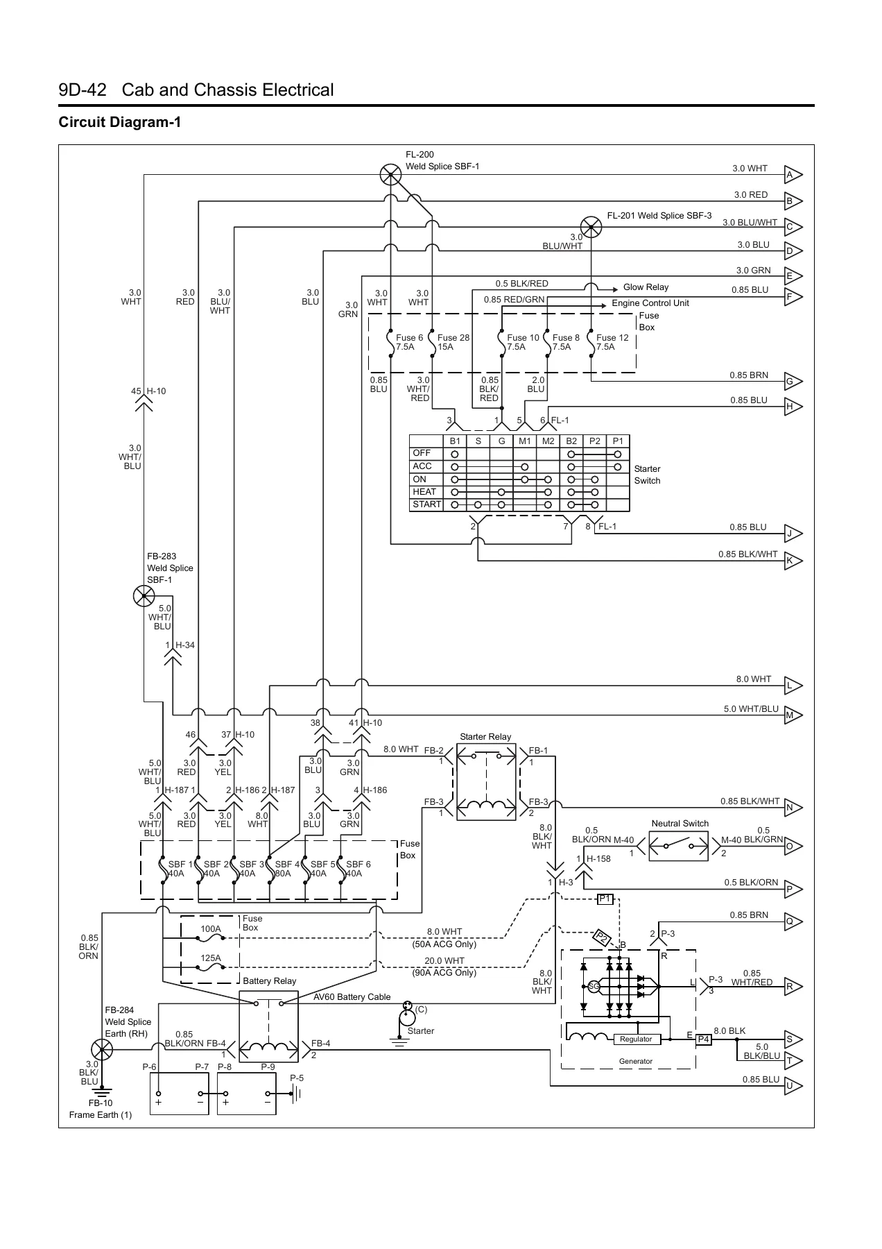
Each system section follows a consistent pattern: a parts location illustration that shows where the components and connectors physically sit on the truck and which harness routing serves them, a circuit diagram showing power supply, loads and grounding points, and connector configuration data for the connectors used in that circuit. That combination is what lets you go from a symptom to a specific connector pin without guessing.
Fuse, Relay and Fusible Link Identification Done Properly
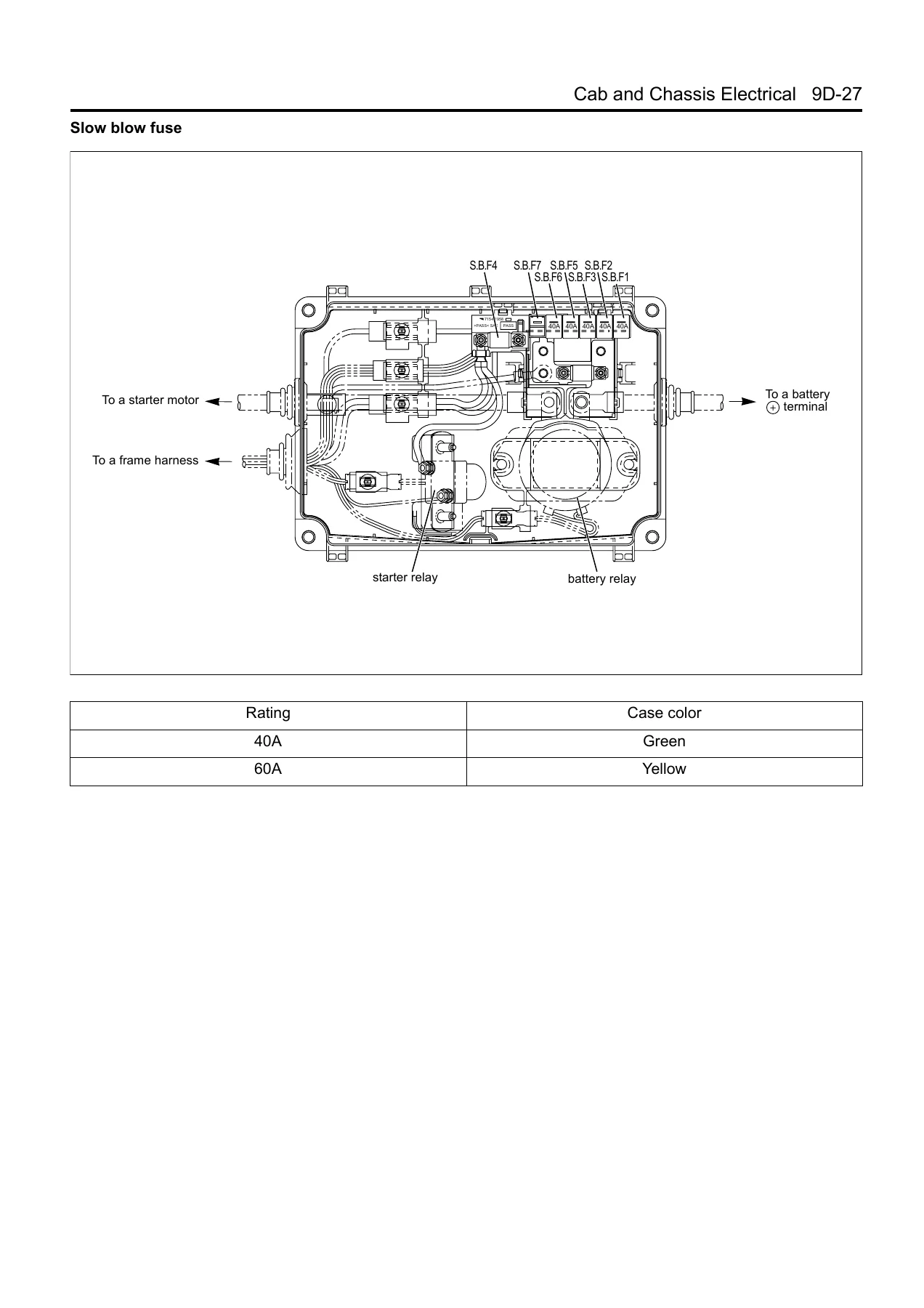
One of the most useful parts of this manual is the fuse identification material. The fuse label section lists every fuse position with its amperage and its labelled function, from the 7.5A headlight high beam left and right circuits, through the engine ECU fuses, ABS, air dryer, back up light, power take off, exhaust brake and retarder fuses, up to the 25A ABS fuse and the 15A spare ignition positions. The reference table of fuse then goes further and names the actual components sitting on each circuit – the relays, switches, motors, solenoids, warning lights and sensors fed by that fuse. The slow blow fuse specifications are also listed with case colours and maximum circuit current, and the slow blow fuse and fusible link layout in the battery relay box is illustrated with the SBF positions identified.
Relay data is given with rated voltage, coil resistance and minimum operating voltage, and diode specifications include peak reverse voltage, transient peak reverse voltage, average output current, working ambient temperature range and storage temperature range, along with connection pattern tables for each diode shape so you can test them correctly with a circuit tester.
Built for Real Diagnosis, Not Just Reference
Because the manual covers the diagnosis system, the data link connector, the ABS and trailer ABS systems, the exhaust brake and retarder system and both engine control system types, it supports actual fault finding rather than only component replacement. The exhaust brake and retarder circuits include the control unit pinouts, the magnetic valve feeds and the earth paths. The engine control system circuits run through the ECM connector pinouts, the sensors, the injector harnesses, the EGR magnetic valves and the starter cut relay logic. The meter and warning light section identifies every indicator in the meter assembly with its bulb rating and colour, which turns a dash light problem into a simple circuit check.
Why This Is the Right Document for the Job
Electrical faults on a 24-volt truck electrical system are rarely solved by swapping parts. They are solved by knowing which fuse feeds which component, which connector pin carries the signal, where the earth point is bolted to the frame, and how the splice points are arranged inside the harness. This manual provides all of that in one place, in the manufacturer’s own numbering and terminology, with the wire colours and sizes printed on every diagram so the truck in front of you matches the page in your hand.
Use it to trace an open circuit through a weld splice, to confirm a relay coil resistance before condemning it, to identify the correct slow blow fuse rating when one has blown, to correctly remove a connector pin without destroying the housing, to repair a chafed harness section with a properly crimped and soldered splice, or to work through the ABS, retarder or engine control circuits methodically. The system repair sections cover starter and charging, glow, all lighting circuits, wipers and washers, power windows and door locks, air conditioning, power tilt, PTO, differential lock, identification lights and the data link connector.
Every section also shows the earth distribution and weld splice arrangement, which is where a large proportion of intermittent electrical faults on these vehicles originate. Knowing where frame earth points, panel earth points, cab earths and battery earths are located – and which circuits share them – shortens diagnosis dramatically.
IMAGES PREVIEW
Instant PDF Delivery
This Isuzu C&E Series cab and chassis electrical workshop manual is delivered as a PDF download immediately after purchase. There is no shipping, no waiting for a parcel and no risk of a lost order. The file opens on any device – workshop PC, laptop, tablet or phone – and any page can be printed for use at the vehicle, which is exactly what you want when you are working under a dash or at the rear frame with a meter in one hand.
Reviews
There are no reviews yet.