
Isuzu N-Series 4HL1 Engine Control System Workshop Manual 2002
Original price was: $39.95.$24.95Current price is: $24.95.
Complete Isuzu N-Series 4HL1 Engine Control System Workshop Manual covering ECM, fuel injection, EGR, diagnostics and all DTCs. Instant PDF download for professional technicians.
Description
Isuzu N-Series 4HL1 Engine Control System Workshop Manual
This Isuzu N-Series 4HL1 Engine Control System Workshop Manual is the complete service and diagnostic guide for the engine management system used on Isuzu 727 (N-Series) vehicles equipped with the 4HL1 engine. Published in 2002 under document number LG4HL-WE-0229DOM, it delivers the full scope of engine control system service information from the manufacturer, including wiring diagrams, diagnostic trouble code charts, component operation theory, and step-by-step diagnostic procedures.
Whether you are diagnosing a check engine light, replacing a sensor, or overhauling the fuel injection system, this 4HL1 Engine Control System Workshop Manual gives you the exact procedures and specifications needed to complete the job correctly.
File Details
- Manual Type: Engine Control System Workshop Manual
- Brand: Isuzu
- Model: N-Series (727 N Series)
- Engine: 4HL1
- Document Number: LG4HL-WE-0229DOM
- Edition: First Edition
- Date: November 2002
- Language: English
- File Format: PDF
- Pages: 267
Chapters Covered
- Engine Control System — Overview, precautions, and general service information
- Precautions on Service — Circuit test tools, on-market electrical equipment, electrostatic discharge damage prevention, wire color identification
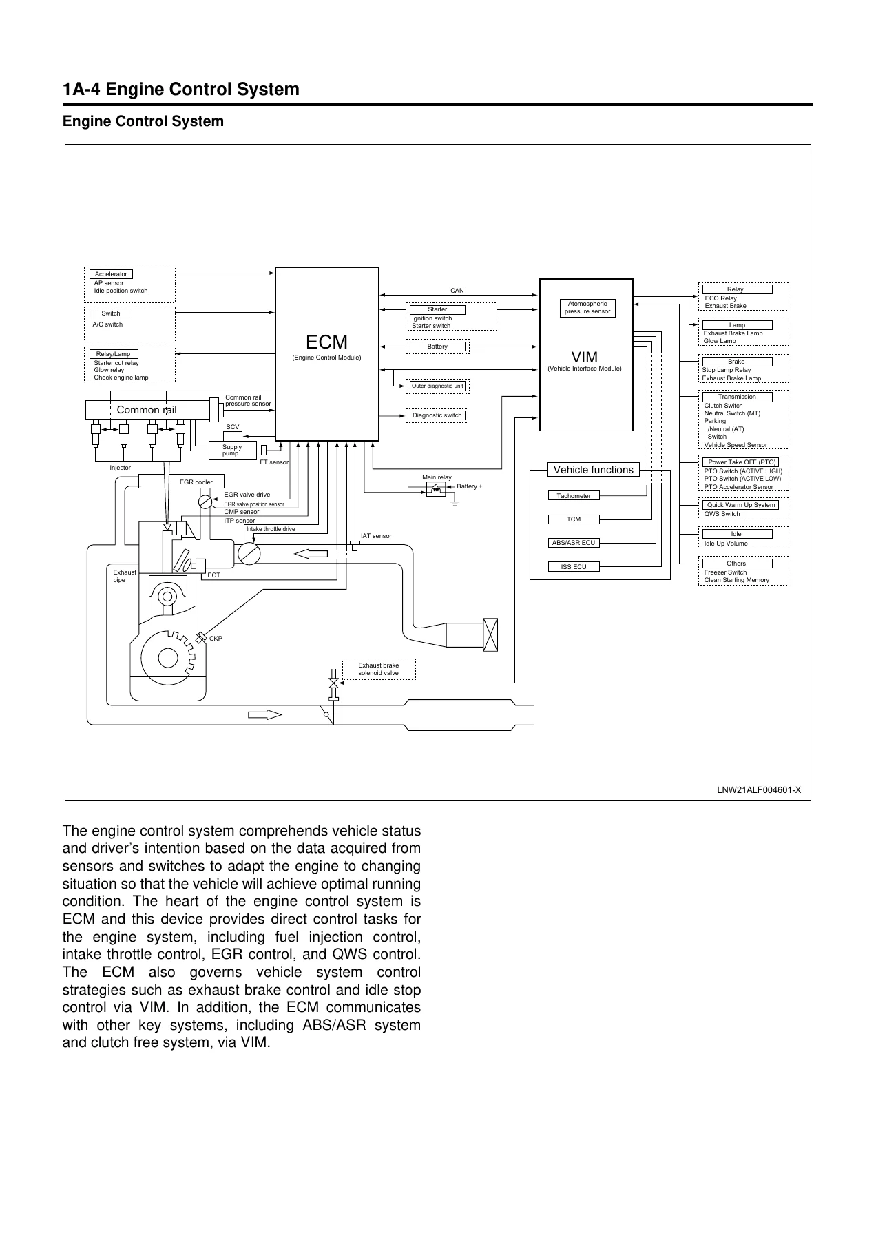
- Function and Operation — ECT sensor, EGR valve and position sensor, intake throttle valve and ITP sensor, CMP sensor, CKP sensor, FT sensor, SCV, common rail pressure sensor, IAT sensor, AP sensor, idle position switch, clutch switch, VS sensor, neutral switch, exhaust brake solenoid valve, atmospheric pressure sensor, ECM, VIM, DLC, CHECK ENGINE lamp
- Powertrain System Components — Fuel injection control, SCV control, intake throttle control, EGR control, QWS control, exhaust brake control, idle stop control
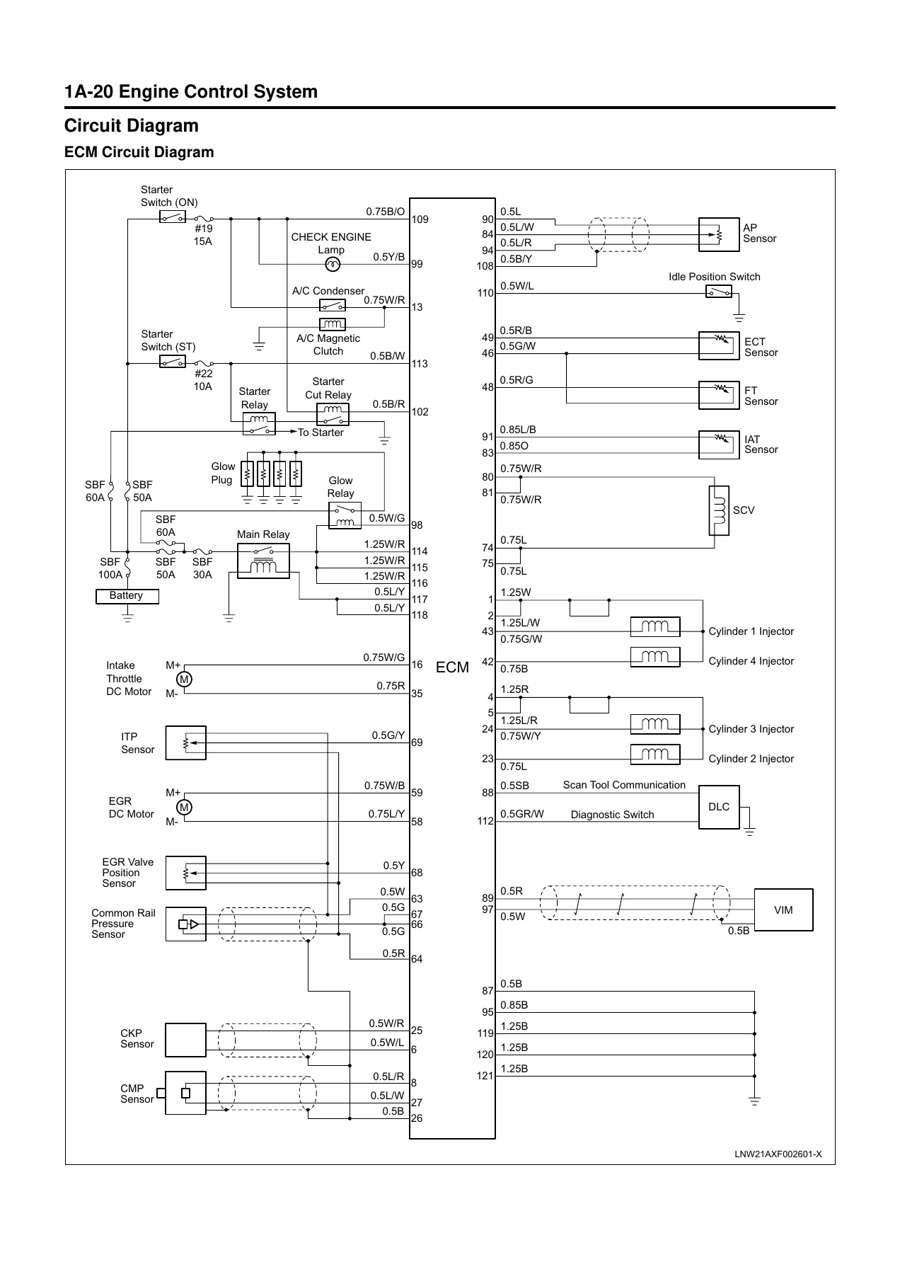
- Circuit Diagram — ECM circuit diagram, ECM/VIM circuit diagrams (multi-page), connector lists, ECM pinouts, VIM pinouts
- Fuse Layout — Fuse box labels and external fuse box
- Relay Layout — Relay box locations and identification
- Strategy-Based Diagnostics — System diagnostics approach, DTC stored procedures, intermittents, verifying vehicle repair
- Functional Check List — Hearing diagnostic, on-board diagnostic system check
- Inactive CHECK ENGINE Lamp Check
- Unblinking CHECK ENGINE Lamp Check
- ECM Power Supply and Grounding System Circuit Check
- Diagnosis with Tech 2 Scan Tool — Connection, menu list, DTC reading, data display, snapshot, actuator tests, typical data values
- DTC14 — CMP Sensor System Fault
- DTC15 — CKP Sensor System Fault
- DTC18 — Starter Degradation (Idle Stop Function)
- DTC22 — IAT Sensor System Fault
- DTC23 — ECT Sensor System Fault
- DTC24 — Accelerator Sensor System Fault
- DTC25 — Vehicle Speed Sensor System Fault
- DTC28 — PTO Accelerator Sensor System Fault
- DTC31 — Idle Up Volume System Fault
- DTC33 — VIM Internal Fault (EEPROM Write Error)
- DTC34 — ECM Internal Fault (Charge Circuit Fault)
- DTC35 — VIM Internal Fault (A/D Conversion Fault)
- DTC43 — ITP Sensor System Fault
- DTC44 — EGR Valve Position Sensor System Fault
- DTC45 — EGR Valve System Fault
- DTC46 — Exhaust Brake System Fault
- DTC51 — ECM Internal Fault (CPU Error / CPU History Error)
- DTC52 — ECM Internal Fault (Sub CPU Error)
- DTC61 — Intake Throttle Valve System Fault
- DTC71 — Barometric Pressure Sensor Fault
- DTC81 — Clutch Switch System Fault
- DTC82 — Neutral Switch System Fault
- DTC84 — CAN Communication Fault (CAN Bus Error)
- DTC86 — CAN Communication Fault (CAN Timeout Error)
- DTC115 — Common Rail Pressure Sensor Fixed Output Fault
- DTC118 — Common Rail Pressure Fault (Control System)
- DTC158 — Injector Power Supply System Short (Common 1)
- DTC159 — Injector Power Supply System Short (Common 2)
- DTC211 — Fuel Temperature Sensor System Fault
- DTC217 — SCV Drive System Short
- DTC227 — No Pump Pressure Feed (Fuel Leak)
- DTC241 — Idle Position Switch Circuit Open Wiring
- DTC242 — Idle Position Switch Circuit Short
- DTC245 — Common Rail Pressure Sensor System Fault
- DTC247 — SCV Drive System Fault
- DTC271 — Cylinder 1 (Injector Drive System) Fault
- DTC272 — Cylinder 2 (Injector Drive System) Fault
- DTC273 — Cylinder 3 (Injector Drive System) Fault
- DTC274 — Cylinder 4 (Injector Drive System) Fault
- DTC277 — Injector Power Supply System Open Wiring Fault (Common 1)
- DTC278 — Injector Power Supply System Open Wiring Fault (Common 2)
- DTC416 — Main Relay System Fault
- DTC417 — Starter Switch System Fault
- DTC543 — High Engine Speed Error
- Default Matrix Table — Symptom diagnosis chart
- Special Tools
- Wiring Harness Repair — Shielded cable, twisted leads, Weather-Pack connector, Com-Pack III, Metri-Pack
This Isuzu 4HL1 engine control system manual is structured as a complete diagnostic and repair resource. It begins with component operation theory so you understand how each sensor, actuator, and control module functions before you touch a connector. From there it moves into circuit diagrams with ECM and VIM pinouts, then into strategy-based diagnostics that teach a systematic approach to any electrical fault. The bulk of the manual is dedicated to individual DTC charts — each one giving you the fault description, judgment criteria, fail-safe actions, and a step-by-step diagnostic flowchart with resistance and voltage values. Whether you are tracing a no-start condition, diagnosing a CAN communication fault, or replacing an injector, the manual provides the exact sequence, test points, and specifications required.
What This Manual Enables You to Do
With this Isuzu N-Series 4HL1 Engine Control System Workshop Manual in hand, you can confidently diagnose and repair the complete engine management system on 727 N-Series vehicles. The manual covers fuel injection control including injector energize time, timing, and SCV position; intake throttle control; EGR control; quick warm-up system; exhaust brake control; and idle stop control. It provides the diagnostic procedures for every engine control related DTC, from sensor circuit faults to injector drive system failures and ECM internal errors.
Technicians will appreciate the detailed circuit diagrams showing ECM and VIM connector pinouts, wire colors, and harness routing. The Tech 2 scan tool section explains how to read live data, perform actuator tests, and interpret typical values at different engine operating conditions. The diagnostic charts give exact resistance ranges, voltage values, and continuity checks for every circuit, eliminating guesswork when tracing an intermittent fault.
This manual matters because engine control system faults on modern diesel engines can be complex — a single symptom may have multiple possible causes, and without the correct diagnostic sequence you risk replacing good parts or missing the root cause entirely. The manufacturer’s procedures in this manual are designed to isolate the fault efficiently and correctly the first time.
IMAGES PREVIEW
Instant PDF Delivery
This Isuzu N-Series 4HL1 Engine Control System Workshop Manual is delivered as an instant PDF download — no shipping, no waiting. You can access it immediately after purchase on any device: laptop, tablet, or smartphone. The PDF is printable, so you can take the relevant pages to the workshop or keep a paper copy for reference. Whether you run a repair shop, maintain a fleet, or service your own Isuzu N-Series truck, this manual gives you the complete engine control system service information you need.
Reviews
There are no reviews yet.