
Isuzu C&E Series 6WF1-TC 6WG1-TC Common Rail Engine Control System Workshop Manual – 2006
Original price was: $39.95.$24.95Current price is: $24.95.
Complete engine control system workshop manual for 2006 Isuzu C&E Series trucks with 6WF1-TC and 6WG1-TC Common Rail engines. Covers DTC diagnostics, wiring diagrams, ECM pin layouts, sensor testing, injector and PCV service, EGR and VGS systems, programming, and symptom-based troubleshooting.
Description
This Isuzu C&E Series 6WF1-TC 6WG1-TC Common Rail Engine Control System Workshop Manual is the Section 1A engine control manual for 2006 model year Isuzu C&E Series trucks equipped with the 6WF1-TC and 6WG1-TC Common Rail engines. It covers the electronic control system in complete detail, from system operation and component layout through fault diagnosis, DTC troubleshooting, wiring diagrams, connector pinouts, and ECM programming.
File Details
- Manual Type: Engine Control System Workshop Manual (Section 1A)
- Brand / Model: Isuzu C&E Series
- Engines Covered: 6WF1-TC, 6WG1-TC (Common Rail)
- Applicable Model Year: 2006
- Document Number: 6WFGCEDG2-WE-0661
- Edition: First Edition, April 2006
- Language: English
- File Format: PDF
- Page Count: Approximately 360 pages
Chapters Covered
- Precautions for Servicing
- Explanation of Functions and Operations
- Electronic Control Systems
- Electronic Control Fuel Injection System
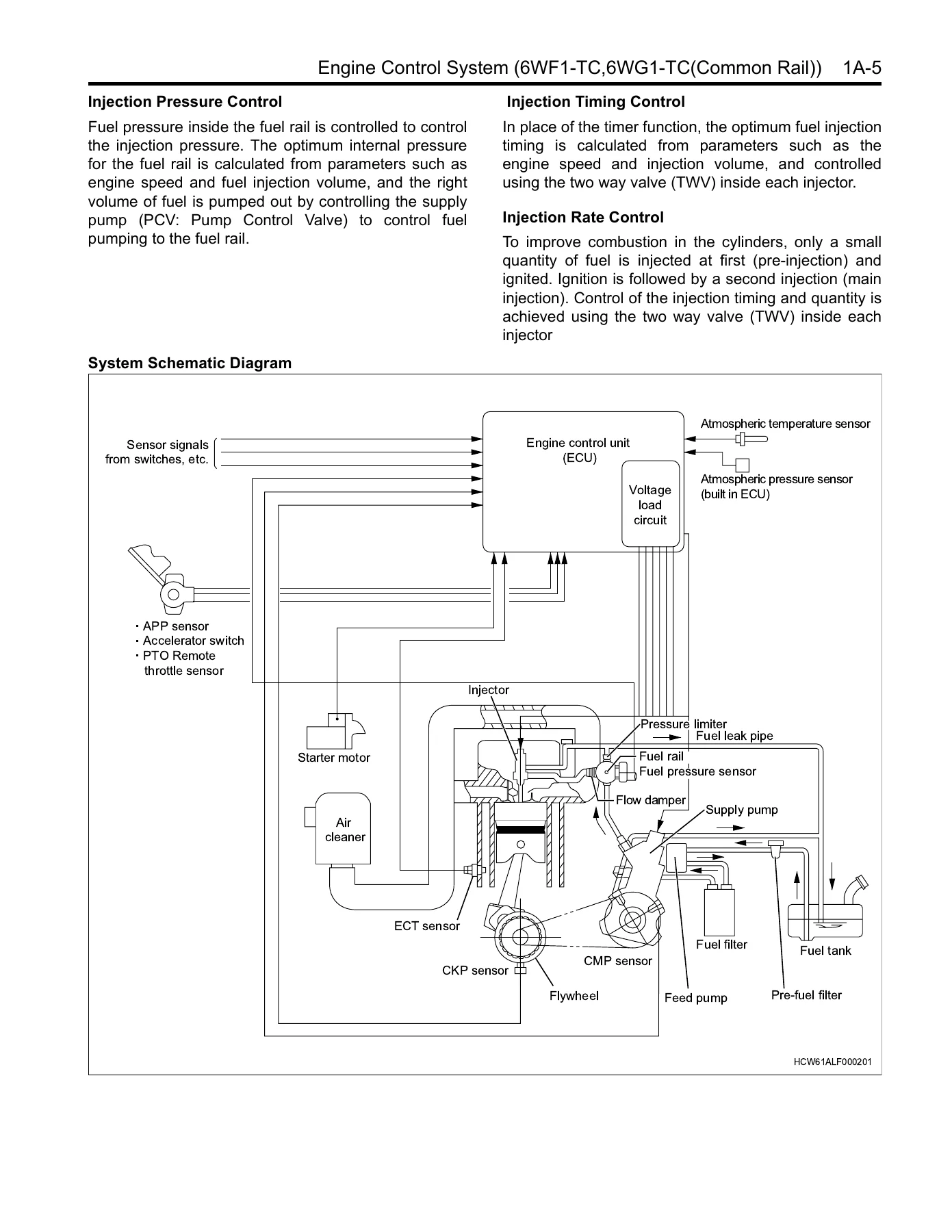
- Injection Volume, Pressure, Timing, and Rate Control
- Exhaust Gas Recirculation (EGR)
- Variable Geometry Turbo System (VGS)
- Idling Control
- PTO Control (Fuel Injection Characteristic Switching)
- Speed Restriction Control
- Cruise Control
- ECM Communications
- Q Adjustment Data
- ECM Functions and Servicing
- Supply Pump
- PCV (Pump Control Valve)
- Fuel Rail
- Flow Damper
- Pressure Limiter
- Fuel Pressure Sensor
- Engine Coolant Temperature Sensor
- Camshaft Position (CMP) Sensor
- Crankshaft Position (CKP) Sensor
- Atmospheric Temperature Sensor
- Accelerator Pedal Position (APP) Sensor
- Vehicle Speed Sensor (VSS)
- Boost Sensor
- Atmospheric Pressure Sensor
- Injectors
- MIL (Check Engine Lamp) Display
- Diagnostics Connector and Data Link Connector (DLC)
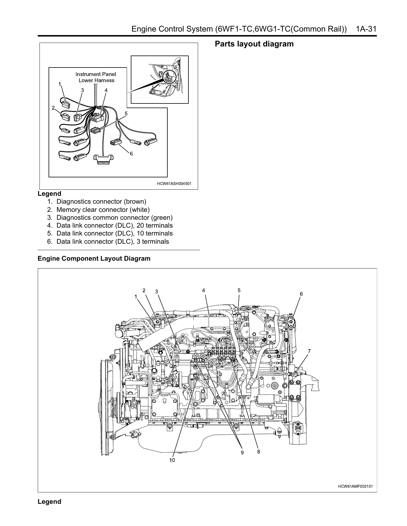
- Parts Layout Diagram
- Circuit Diagram
- Connector List
- Fault Diagnosis Process
- Breakdown Diagnosis Using the Scan Tool
- Function Inspection List
- Oral Consultation
- On-Board Diagnosis (OBD) System Check
- Checking the MIL Lighting Circuit System
- Checking the MIL Flashing Control System
- Checking the Scan Tool Circuit System
- Checking the Starting System
- Checking the Fuel System
- Checking the Intake Air System
- Checking the Exhaust System
- Checking the EGR
- Checking the Engine Control Module (ECM) Power Supply and Ground Circuit
- Checking the PTO
- Table of Diagnostics Codes
- DTC P0014 through P0543 (complete diagnostic procedures)
- Symptom List (Engine Stall, Engine Hunting/Rough Idle, Lack of Power, Excessive White Smoke, Excessive Black Smoke, Idling Revolutions Cannot Be Adjusted, etc.)
- Special Tool
- Programming (Injector ID Code Registration, Q Adjustment Data Upload/Download)
Beyond the chapter list, this manual provides the complete diagnostic and repair workflow for the engine control system. The DTC section spans dozens of individual trouble codes, each with circuit descriptions, set conditions, diagnostic aids, and step-by-step troubleshooting charts. The symptom-based diagnostics cover real-world complaints like rough idle, lack of power, excessive smoke, and engine stall, walking through the likely causes in the order a technician should check them. Wiring diagrams and connector lists provide the electrical detail needed to trace faults accurately, while the ECM pin layouts and programming instructions support component replacement and setup.
Diagnostic Trouble Code Coverage
Every DTC in the manual includes a flash code reference, a circuit description, the conditions that set the code, the backup actions the ECM takes when the code is active, and the conditions required to clear it. The diagnostic charts then walk through the specific steps needed to confirm the fault and identify the failed component. Codes cover the CMP sensor, CKP sensor, atmospheric and coolant temperature sensors, accelerator pedal position sensor, vehicle speed sensor, boost sensor, atmospheric pressure sensor, fuel pressure sensor, PCV1 and PCV2, injectors on all six cylinders, injector common circuits, VGS magnetic valves, EGR magnetic valves, main relay, VGS and EGR fail safe relays, and more.
Symptom-Based Troubleshooting
The symptom list addresses the problems technicians and owners most commonly encounter: engine stall, hunting or rough idle, lack of power or sluggishness, excessive white smoke, excessive black smoke, and idle speed adjustment problems. Each symptom has its own diagnostic table with a logical sequence of checks, starting with the simplest and most likely causes and progressing to more involved tests. This structure saves time by preventing unnecessary teardown and helps ensure that the real cause is found rather than a symptom being masked.
Electrical and Wiring Reference
The circuit diagrams and connector lists are extensive. The manual includes ECM pin layout tables showing the terminal number, signal name, and function for every pin, along with connector face diagrams that identify terminal positions. Wiring color codes and wire size notation are explained so you can interpret the diagrams correctly. This is the reference material needed for tracing broken wires, shorts, poor connections, and other electrical faults that are common sources of engine control problems.
Programming and Component Replacement
When an ECM or injector is replaced, the new component must be programmed. The manual covers the full procedure using the Tech2 scan tool, including uploading and downloading injector ID codes, registering Q adjustment compensation data, and checking history information. Step-by-step screen references and menu paths are provided so the programming can be completed without guesswork. This section is critical for avoiding post-repair driveability problems and ensuring the engine runs to specification.
What This Manual Helps You Do
This is not a general overview. It is a working reference for the specific engine control systems in the 2006 Isuzu C&E Series with 6WF1-TC and 6WG1-TC common rail engines. With it, you can:
- Read and clear diagnostic trouble codes (DTCs) and follow the correct diagnostic path for each one
- Diagnose engine performance problems using symptom-based flow charts and scan tool data
- Test and replace sensors, injectors, the supply pump, PCV, fuel rail components, and EGR/VGS hardware
- Trace wiring faults using the circuit diagrams, connector lists, and ECM pin layout tables
- Perform injector ID code registration and Q adjustment data programming after ECM or injector replacement
- Check and repair the starting system, fuel system, intake air system, exhaust system, and EGR system
- Verify repairs with the OBD system check and the function inspection list
Why the Right Procedures Matter
The 6WF1-TC and 6WG1-TC are common rail engines with electronically controlled injection, EGR, and variable geometry turbocharging. A guess-and-check approach to diagnosis can waste hours, damage sensitive components, or leave the vehicle with unresolved faults. This manual provides the measured values, resistance checks, voltage references, and diagnostic sequences that let you isolate the fault instead of replacing parts blindly. The ECM programming section is especially important: after replacing the ECM or injectors, the injector ID codes and Q adjustment data must be correctly registered for the engine to run properly.
IMAGES PREVIEW
Instant PDF Delivery
The manual is delivered as an instant PDF download after purchase. There is no physical book to wait for, no shipping cost, and no delay. You can open it on a laptop, tablet, or phone, search across the document, and print the pages you need for the workshop. Whether you are a professional technician working on a fleet or an owner-operator maintaining your own truck, this PDF gives you permanent access to the engine control system documentation for the Isuzu C&E Series 6WF1-TC and 6WG1-TC engines.
Reviews
There are no reviews yet.