
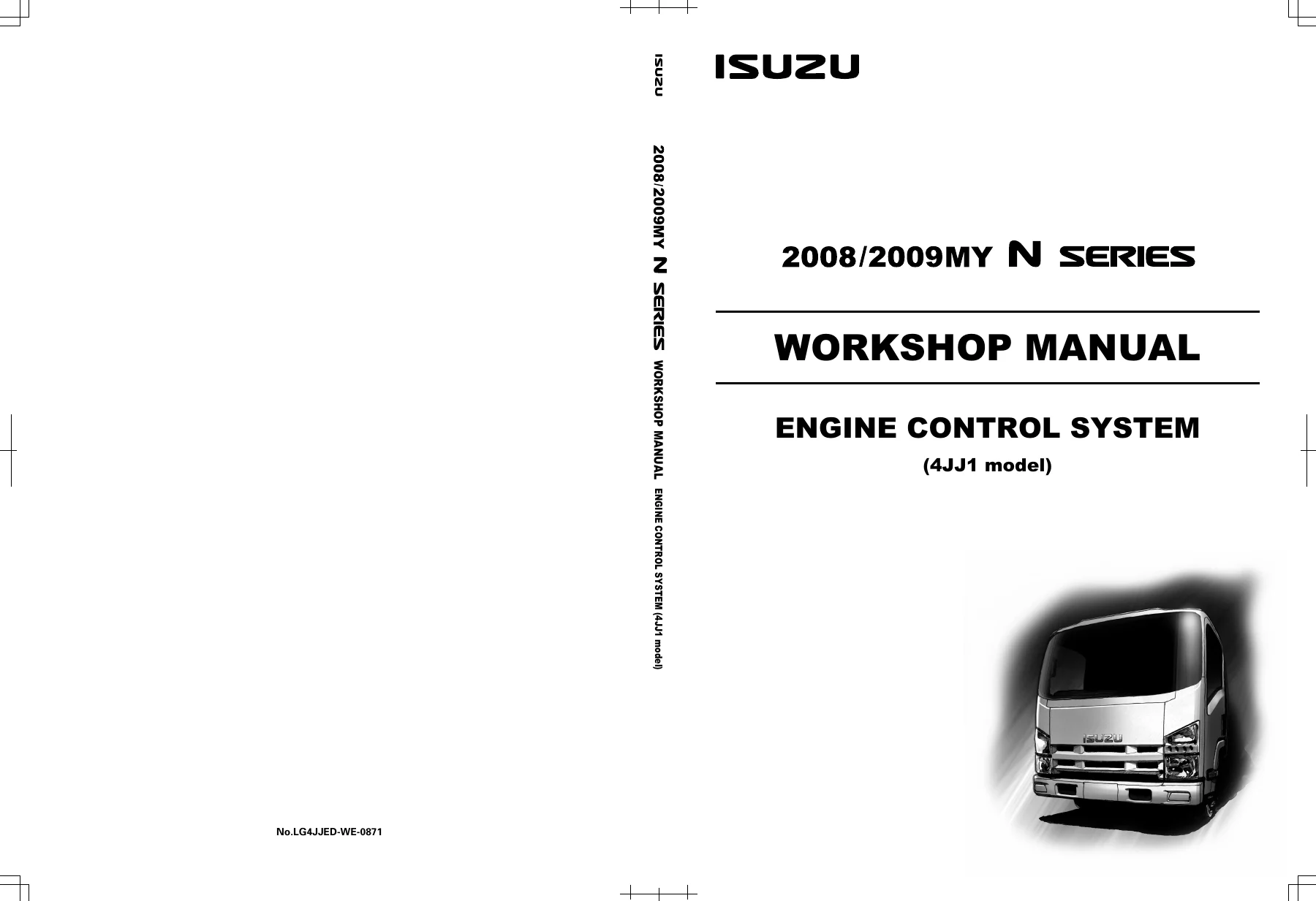
Isuzu N Series 4JJ1 Engine Control System Workshop Manual 2008-2009MY – PDF Download
Original price was: $44.95.$27.95Current price is: $27.95.
Complete Isuzu N Series 4JJ1 engine control system workshop manual for 2008/2009MY. Covers DTC diagnostics, ECM wiring, fuel system, EGR, DPD, turbocharger, glow control, exhaust brake and more. 388-page PDF, Fourth Edition, January 2009.
Description
Isuzu N Series 4JJ1 Engine Control System Workshop Manual
This is the complete Isuzu workshop manual for the Engine Control System on 2008/2009MY N Series trucks equipped with the 4JJ1 diesel engine. Published by Isuzu Motors Limited and issued in January 2009 as the Fourth Edition, this manual gives technicians the full diagnostic and repair procedure set for the 4JJ1 engine management system, from basic sensor specifications through to the complete diagnostic trouble code library and ECM replacement programming. Whether you are diagnosing a stubborn intermittent fault, replacing an ECM, or working through a no-start condition on an NHR, NLR, NMR, NPR, NNR or NLS model, this manual provides the step-by-step test procedures and reference data you need.
File Details
- Manual Type: Engine Control System Workshop Manual
- Brand: Isuzu
- Model: N Series (4JJ1 model)
- Coverage: 2008/2009MY
- Language: English
- Page Count: 388 pages
- File Format: PDF
- Document Number: LG4JJED-WE-0871
- Edition: Fourth Edition
- Publication Date: January 2009
What This 4JJ1 Engine Control System Manual Covers
This Isuzu N Series workshop manual focuses exclusively on the engine control system for the 4JJ1 powerplant. It opens with the specification data you need for accurate sensor testing – engine coolant temperature vs. resistance, exhaust temperature vs. resistance, fuel temperature vs. resistance, intake air temperature vs. resistance for both Euro 4 and non-Euro 4 specifications, and an altitude vs. barometric pressure chart. From there it moves into the diagnostic trouble code type definitions, explaining Type A, B, C and D DTC behaviour, how the MIL and SVS lamps are triggered, and the conditions under which codes clear. The full DTC list covers every code in the system, with flash codes, Euro 4 and non-Euro 4 type classifications, and descriptor.
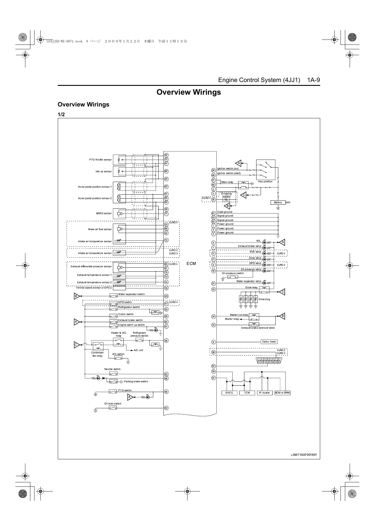
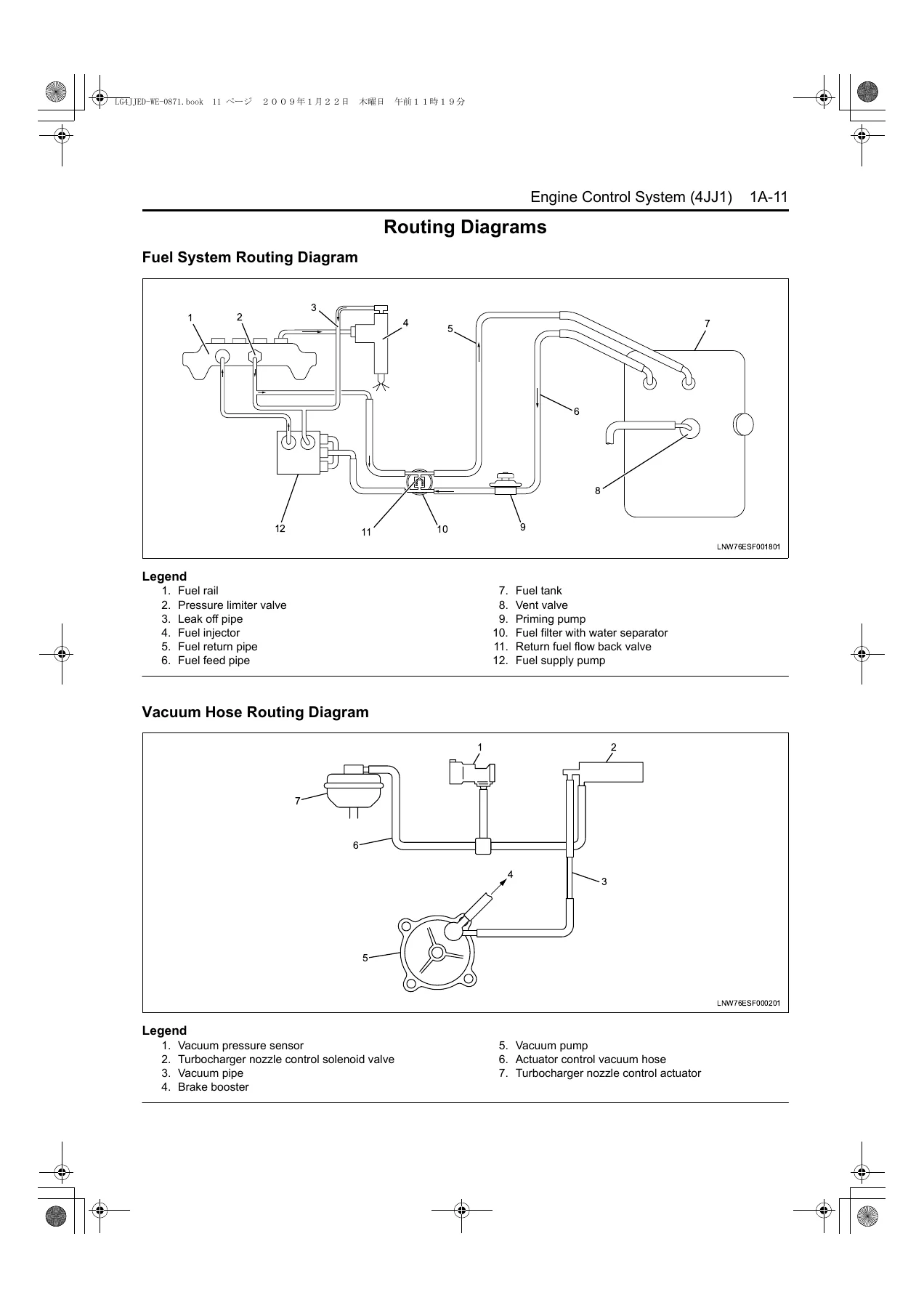
The wiring and routing section includes overview wirings for the ECM, fuel system routing diagram, and vacuum hose routing diagram. The component locator section provides engine controls component views, ECM connector end views (J14 and E12 connectors with pin numbers, wire colours and pin functions), and connector end views for every major sensor and actuator in the system – accelerator pedal position sensor, barometric pressure sensor, clutch switch, camshaft position sensor, crankshaft position sensor, data link connector, DPD regeneration switch, EGR valve, engine coolant temperature sensor, engine warm up switch, exhaust brake solenoid valve, exhaust differential pressure sensor, exhaust temperature sensors, exhaust throttle solenoid valve, fuel injectors, fuel rail pressure regulator, fuel rail pressure sensor, glow plug, mass air flow/intake air temperature sensor, intake throttle valve, idle up sensor, PTO switch, PTO throttle sensor, turbocharger nozzle control solenoid valve, VNT vacuum pressure sensor, and vehicle speed sensor.
Chapters Covered
- Specifications
- Temperature vs. Resistance (Engine Coolant, Exhaust, Fuel, Intake Air)
- Altitude vs. Barometric Pressure
- Diagnostic Trouble Code (DTC) Type Definitions
- Diagnostic Trouble Code (DTC) List
- Overview Wirings
- Routing Diagrams (Fuel System, Vacuum Hose)
- Component Locator
- Engine Controls Component Views
- Engine Control Module (ECM) Connector End Views
- Engine Control Connector End Views
- Diagnostic Information and Procedures
- Engine Control System Check Sheet
- Diagnostic Starting Point – Engine Controls
- Diagnostic System Check – Engine Controls
- Scan Tool Data List
- Scan Tool Data Definitions
- Scan Tool Output Controls
- Scan Tool Does Not Power Up
- Scan Tool Does Not Communicate with CAN Device (Euro 4)
- Scan Tool Does Not Communicate with Keyword Device
- Lost Communication with ECM
- Engine Cranks but Does Not Run
- DTC P0016 (Flash Code 16) – Crankshaft/Camshaft Position Correlation
- DTC P0045 (Flash Code 33) – Turbocharger Boost Control Solenoid Circuit
- DTC P0079/P0080 (Flash Code 38) – Exhaust Valve Control Solenoid Circuit
- DTC P0087 (Flash Code 225) – Fuel Rail/System Pressure Too Low
- DTC P0088 (Flash Code 118) – Fuel Rail/System Pressure Too High
- DTC P0089 (Flash Code 151) – Fuel Pressure Regulator Performance
- DTC P0091/P0092 (Flash Code 247) – Fuel Pressure Regulator Control Circuit
- DTC P0093 (Flash Code 227) – Fuel System Leak Detected
- DTC P0101 (Flash Code 92) – Mass Air Flow Sensor Circuit Range/Performance
- DTC P0102/P0103 (Flash Code 91) – MAF Sensor Circuit Low/High Input
- DTC P0107/P0108 (Flash Code 32) – Manifold Absolute Pressure Sensor Circuit
- DTC P0112/P0113 (Flash Code 22) – Intake Air Temperature Sensor Circuit
- DTC P0116 (Flash Code 23) – Engine Coolant Temperature Sensor Range/Performance
- DTC P0117/P0118 (Flash Code 23) – Engine Coolant Temperature Sensor Circuit
- DTC P0122/P0123 (Flash Code 43) – Throttle Position Sensor Circuit
- DTC P0182/P0183 (Flash Code 211) – Fuel Temperature Sensor Circuit
- DTC P0192/P0193 (Flash Code 245) – Fuel Rail Pressure Sensor Circuit
- DTC P0201/P0202/P0203/P0204 (Flash Code 271-274) – Injector Circuit Open
- DTC P0217 (Flash Code 542) – Engine Coolant Over Temperature
- DTC P0219 (Flash Code 543) – Engine Overspeed Condition
- DTC P0234 (Flash Code 42) – Turbocharger Overboost
- DTC P0299 (Flash Code 65) – Turbocharger Underboost
- DTC P0335/P0336 (Flash Code 15) – Crankshaft Position Sensor Circuit
- DTC P0340/P0341 (Flash Code 14) – Camshaft Position Sensor Circuit
- DTC P0380/P0381 (Flash Code 66/67) – Glow Plug and Indicator Circuit
- DTC P0401 (Flash Code 93) – EGR Flow Insufficient
- DTC P0404/P0409 (Flash Code 45/44) – EGR Control Circuit and Position Sensor
- DTC P0426/P0427/P0428 (Flash Code 143/48) – Catalyst Temperature Sensor
- DTC P042B/P042C/P042D (Flash Code 145/49) – Catalyst Temperature Sensor 2
- DTC P0477/P0478 (Flash Code 46) – Exhaust Pressure Control Valve
- DTC P0500/P0502/P0503 (Flash Code 25) – Vehicle Speed Sensor
- DTC P0560/P0563 (Flash Code 155/35) – System Voltage
- DTC P0601/P0602/P0604/P0606/P060B (Flash Code 53/154/153/51/36) – ECM Internal
- DTC P0633 (Flash Code 176) – Immobilizer Not Programmed
- DTC P0638 (Flash Code 61) – Throttle Actuator Control Range/Performance
- DTC P0641/P0651/P0697 (Flash Code 55/56/57) – Sensor Reference Voltage Circuits
- DTC P0650 (Flash Code 77) – MIL Control Circuit
- DTC P0685/P0687 (Flash Code 416) – ECM Power Relay Control Circuit
- DTC P1093 (Flash Code 227) – Fuel Rail Pressure Too Low
- DTC P1261/P1262 (Flash Code 34) – Injector Positive Voltage Control Circuit
- DTC P1404 (Flash Code 45) – EGR Position Fault
- DTC P1455 (Flash Code 132) – PM Over Accumulation
- DTC P1471 (Flash Code 149) – DPD Insufficient Regeneration
- DTC P161B (Flash Code 179) – Immobilizer Wrong Response
- DTC P1621 (Flash Code 54) – Control Module Long Term Memory
- DTC P1664/P1669 (Flash Code 76/75) – SVS/DPD Lamp Control Circuit
- DTC P2122/P2123/P2127/P2128/P2138 (Flash Code 121/122/124) – Pedal Position Sensor
- DTC P2146/P2149 (Flash Code 158/159) – Fuel Injector Group Supply Voltage
- DTC P2227/P2228/P2229 (Flash Code 71) – Barometric Pressure Sensor
- DTC P242F (Flash Code 131) – DPD Restriction
- DTC P2452/P2453/P2454/P2455/P2456/P2458 (Flash Code 142/141/47/139) – DPD Differential Pressure
- DTC P2527/P2528 (Flash Code 233) – Vacuum Pressure Sensor
- DTC P253A (Flash Code 28) – PTO Sensor Circuit
- DTC P256A (Flash Code 31) – Engine Idle Speed Selector Sensor
- DTC U0073/U0101/U0167 (Flash Code 84/85/177) – Communication Bus
- EGR Control System Check
- Glow Control System Check
- Engine Warm Up Control System Check
- Exhaust Brake Control System Check
- Diesel Particulate Defuser (DPD) Control System Check
- Symptoms – Engine Controls
- Repair Instructions – ECM Replacement
- Service Programming System (SPS) – Remote and Pass-Thru Procedures
- Description and Operation
- Special Tools and Equipment
Diagnostic Depth for the 4JJ1 Engine Management System
The diagnostic section of this Isuzu N Series 4JJ1 manual is built around a logical workflow. The Diagnostic System Check – Engine Controls gives you the starting point for any driveability concern, with separate paths for Euro 4 and non-Euro 4 specifications. The scan tool data list and definitions cover every parameter the ECM monitors, including typical values at idle and at 1700 RPM for Euro 2, Euro 3 and Euro 4 configurations. The scan tool output controls section explains how to command fuel pressure control, pre-injection control, injection timing, injector forced drive, cylinder balance test, intake throttle solenoid control, EGR solenoid control, turbocharger solenoid control, glow relay control, exhaust brake control, exhaust throttle control, fuel supply pump learn resetting, and DPD regeneration controls.
Each DTC section follows a consistent structure: circuit description, conditions for running the DTC, conditions for setting the DTC, action taken when the DTC sets, conditions for clearing the DTC, diagnostic aids, and a full step-by-step circuit/system testing table with value(s), Yes and No routing. This means you can work through a P0087 fuel rail pressure too low code, a P0299 turbocharger underboost code, or a P2453 DPD differential pressure code with the exact test sequence Isuzu technicians use. The manual also covers the non-DTC diagnostic checks for EGR, glow, engine warm up, exhaust brake, and DPD systems, plus a full symptom-based diagnostic section covering hard start, rough idle, high idle, cuts out, surges, lack of power, hesitation, abnormal combustion noise, poor fuel economy, excessive black smoke, excessive white smoke, DPD manual regeneration frequently, and DPD regeneration long time.
Models Covered
This manual applies to 2008/2009MY Isuzu N Series vehicles equipped with the 4JJ1 engine. Model designations referenced in the manual include NHR, NLR, NMR, NNR, NPR and NLS. The manual is written for both Euro 4 specification and except Euro 4 specification variants, with differences noted throughout the diagnostic procedures, wiring, and component views.
Who This Manual Is For
This Isuzu N Series 4JJ1 Engine Control System Workshop Manual is aimed at professional diesel technicians, fleet maintenance workshops, and experienced owners who need to diagnose and repair the engine management system on these trucks. The level of detail – ECM connector pinouts, wire colours, DTC type definitions, freeze frame/failure record behaviour, scan tool data definitions, and step-by-step circuit testing – makes it suitable for anyone who needs to move beyond generic OBD codes and work with the actual Isuzu diagnostic process. It is not a beginner’s guide to diesel engines; it assumes you have a scan tool and a digital multimeter and know how to use them.
Why This Manual Matters
The 4JJ1 engine control system is complex, with common rail fuel injection, variable nozzle turbocharging (Euro 4), exhaust gas recirculation, diesel particulate defuser regeneration, glow control, exhaust brake control, and immobilizer integration. Diagnosing a fault without the correct procedure can lead to unnecessary parts replacement – fuel injectors, fuel supply pumps, ECMs, sensors – when the actual problem is a wiring fault, a skewed sensor, or a learning procedure that has not been completed. This manual gives you the correct specifications, the correct test values, and the correct diagnostic sequence so you can identify the root cause efficiently and repair it properly. It also covers critical programming procedures such as fuel injector ID code programming, ECM replacement and immobilizer security information programming, fuel supply pump relearn, and DPD status resetting, which are essential when components are replaced.
Get Instant Access to the Isuzu N Series 4JJ1 Engine Control System Workshop Manual
IMAGES PREVIEW
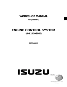
This Isuzu N Series 4JJ1 Engine Control System Workshop Manual is delivered as an instant PDF download – no shipping, no waiting, no physical book to lose. After payment you can download the file immediately and access it on any device: laptop, tablet, or smartphone. The PDF is printable, so you can print the DTC procedure you are working on and take it to the vehicle, or print the ECM connector end views and wiring diagrams for the workshop wall. Whether you are diagnosing a single fault or maintaining a fleet of N Series trucks, this 388-page manual gives you the complete engine control system reference in one file.
Reviews
There are no reviews yet.