
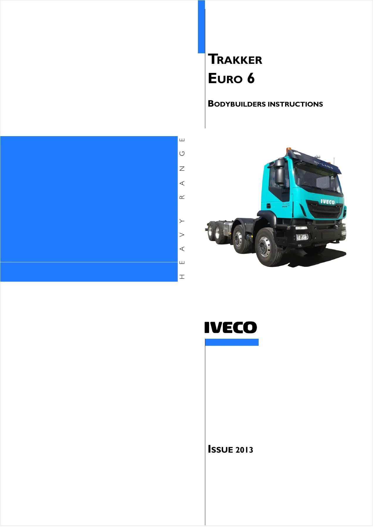
Iveco Trakker Euro 6 Bodybuilders Instructions Manual 2013 – Chassis Modifications, PTO & SCR Guide
Original price was: $34.95.$21.95Current price is: $21.95.
Official IVECO bodybuilder instructions for the Trakker Euro 6 range (doc 603.95.646, issue 2013). Covers chassis interventions, superstructure applications, power take-offs, electronic subsystems and SCR exhaust system guidance for upfitters and converters.
Description
Iveco Trakker Euro 6 Bodybuilders Instructions Manual
This Iveco Trakker Euro 6 Bodybuilders Instructions Manual (publication number 603.95.646, issue 2013) is the working reference for workshops, bodybuilders and upfitters converting the Trakker Euro 6 chassis. It sets out the technical rules, dimensions, permitted masses, and step-by-step procedures required to fit or transform the original vehicle while preserving its functionality, safety and reliability. The manual is written for qualified, specialised staff and covers the full scope of bodybuilding work: chassis modification, superstructure mounting, power take-off installation, electrical and electronic interfacing, and the AdBlue/SCR exhaust system.
File Details
- Manual type: Bodybuilder / upfitter instructions manual
- Brand: IVECO
- Model range: Trakker Euro 6 (heavy range)
- Language: English
- Publication number: 603.95.646
- Base / issue date: 09/2013 – Issue 2013
- Page count: 212
- File format: PDF
Chapters Covered
- Section 1 – General Information: scope of the guidelines, technical documentation, IVECO authorisation, responsibilities, legislative requirements, multi-stage approval, guarantees, quality system management, accident prevention, ecology and recycling, vehicle management by the bodybuilder, vehicle names, trademarks and symbols, dimensions and ground, instructions for proper functioning and accessibility, conventions
- Section 2 – Chassis Interventions: general chassis modification standards, drills on the chassis, rust and paint protection, wheelbase modification, rear overhang modification, installing the tow hook, assembling an additional axle, gearbox modification, modifying the engine air intake and exhaust systems, engine cooling system, additional heating and air conditioning, work on the cab, changing tyre size, work on the braking system, electrical system current interventions and draws, part relocation and anchorage, transport of hazardous materials (ADR), installing a retarder, under-run protection bar, rear mud guards and wheel arches, rain flap, side protections, wheel chocks
- Section 3 – Applications of Superstructures: construction of the counter chassis, elements making up the counter chassis, connection between chassis and counter chassis, container application (fixed bodies, tipper bodies, heavy-duty and light-duty services, roll-off containers), tractor for semi-trailer (fifth wheel, advancement, supporting structure), transport of inseparable materials, installation of tanks and loose material containers, installing a crane (behind cab, rear overhang, removable), vehicles for council/fire service and special uses, front installation of snow plough attachments, application of a winch, concrete mixer installation, interchangeable outfits
- Section 4 – Power Take-Offs: general specifications, PTO from gearbox, PTO from transfer box, PTO from drive line, PTO from engine (front and rear), PTO management, standard configurations, EM Expansion Module wiring and connections
- Section 5 – Electronic Sub-Systems: electronic systems overview, bodybuilder connectors, FMS Fleet Management System, electrical circuit modifications, electrical system current interventions and draws
- Section 6 – Special Instructions for SCR Exhaust System: general information, the nitrogen oxide catalytic reduction principle, interventions on the AdBlue tank, moving AdBlue system components, operations on pipes for AdBlue and heating water
Section 1 establishes the working relationship between IVECO and the bodybuilder, including who is responsible for what, when formal authorisation is required, and how multi-stage approval works under Directive 2007/46/EC. Section 2 is the technical core for anyone cutting, drilling, welding or reinforcing the Trakker Euro 6 chassis: it lists the permitted materials, hole sizes and edge distances, side member section dimensions, weld preparation and cooling rules, and how to protect the frame against corrosion after modification. It also covers wheelbase and rear overhang changes, tow hook and drawbar coupling installation, additional axles, and gearbox adjustments for altered driveline angles. Section 3 turns to the superstructure itself – counter chassis construction, cross members, stiffening methods, and the elastic versus rigid connection choices that determine how much the added structure contributes to overall rigidity. It then walks through specific fit-outs: fixed and tipper bodies, roll-off containers, semi-trailer tractors, tanks, cranes (behind cab and rear overhang), snow plough attachments, winches, concrete mixers and interchangeable outfits. Section 4 covers the full power take-off landscape: gearbox, transfer box, drive line and engine PTOs, with torque tables, ratio tables, maximum length tables and the EM Expansion Module wiring diagrams needed to integrate PTOs with the vehicle’s electronic management. Section 5 explains the Easy Mux electronic architecture, the bodybuilder connectors inside the cab and on the frame, FMS connection, and the rules for drawing current or modifying the electrical system without compromising safety or warranty. Section 6 addresses the Hi-e SCR exhaust system: AdBlue dosing and supply modules, tank options and materials, pipe routing, siphoning requirements, and the strict cleanliness and assembly sequence rules that apply whenever the AdBlue circuit is disturbed.
What This Manual Gives the Bodybuilder
The Iveco Trakker Euro 6 Bodybuilders Instructions is not a generic guide. It is the chassis-specific rulebook for the Trakker Euro 6 range, and it exists because converting a heavy commercial vehicle incorrectly has consequences: cracked side members, voided warranty, failed approval, unstable handling, overheated brakes, or an AdBlue system that crystallises and stops working. Every procedure in the manual is tied to the actual dimensions, materials and system architecture of the Trakker Euro 6, so the bodybuilder is not guessing.
For chassis work, the manual gives the permitted static stress limit, the side member section dimensions for each model, the minimum edge distances for new holes, the weld preparation angles, the reinforcement sizing tables for wheelbase elongation and rear overhang changes, and the cross member spacing rules. It also explains when IVECO authorisation is mandatory – for example, particular wheelbase changes, work on the braking system, steering modifications, stabiliser bar changes, cab and cab mount modifications, intake/exhaust/SCR component changes, retarder fitting, PTO applications, tyre size variations, and hook organism modifications. Getting this wrong can void the guarantee, and the manual states that plainly.
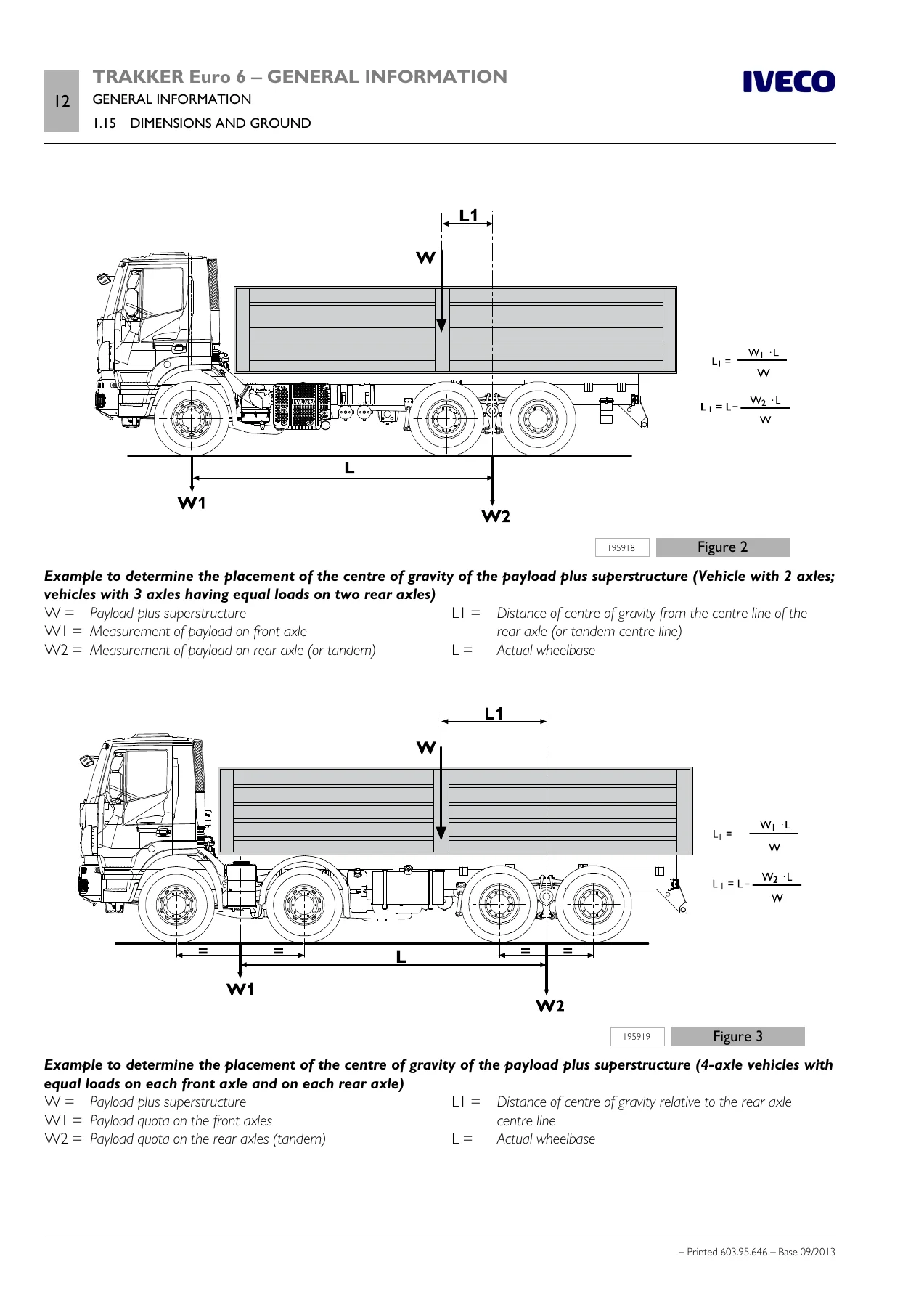
For superstructure work, the manual provides the counter chassis material specifications, the recommended C-profile section modulus table, the rules for tapering longitudinal profiles, and the connection methods (brackets, clevis fasteners, longitudinal and transverse sealing plates) with their respective stiffness characteristics. It tells the bodybuilder when to use elastic connections and when rigid connections are required, and it explains how different superstructures – tippers, cranes, tanks, concrete mixers – change those requirements. The crane section alone covers the calculation of the static moment, the reinforcement sections required for cranes behind the cab versus rear overhang cranes, and the stability precautions that must be taken.
For power take-offs, the manual is unusually detailed. It lists the PTO options available for each gearbox (9 S 1310 TO, 16 S 1820 TO, 16 S 2220 TO, 16 S 2520 TO, 12 AS 2330 TO, 16 AS 2630 TO), the total PTO ratio, the available torque at 1500 rpm, the assembly side, and whether the PTO is suitable for sporadic or continuous use. It gives the engine speed at maximum output power for CURSOR 9 and CURSOR 13 engines, the gear ratio at highest speed for each gearbox, and the maximum possible drive shaft lengths for different joint dimensions and shaft speeds. It also explains the EM Expansion Module PTO management logic: how PTO switches are wired, how engagement conditions are configured, how Intermediate Speed Control modes are prioritised, and why operating a PTO without connecting it to the EM control unit is not recommended.
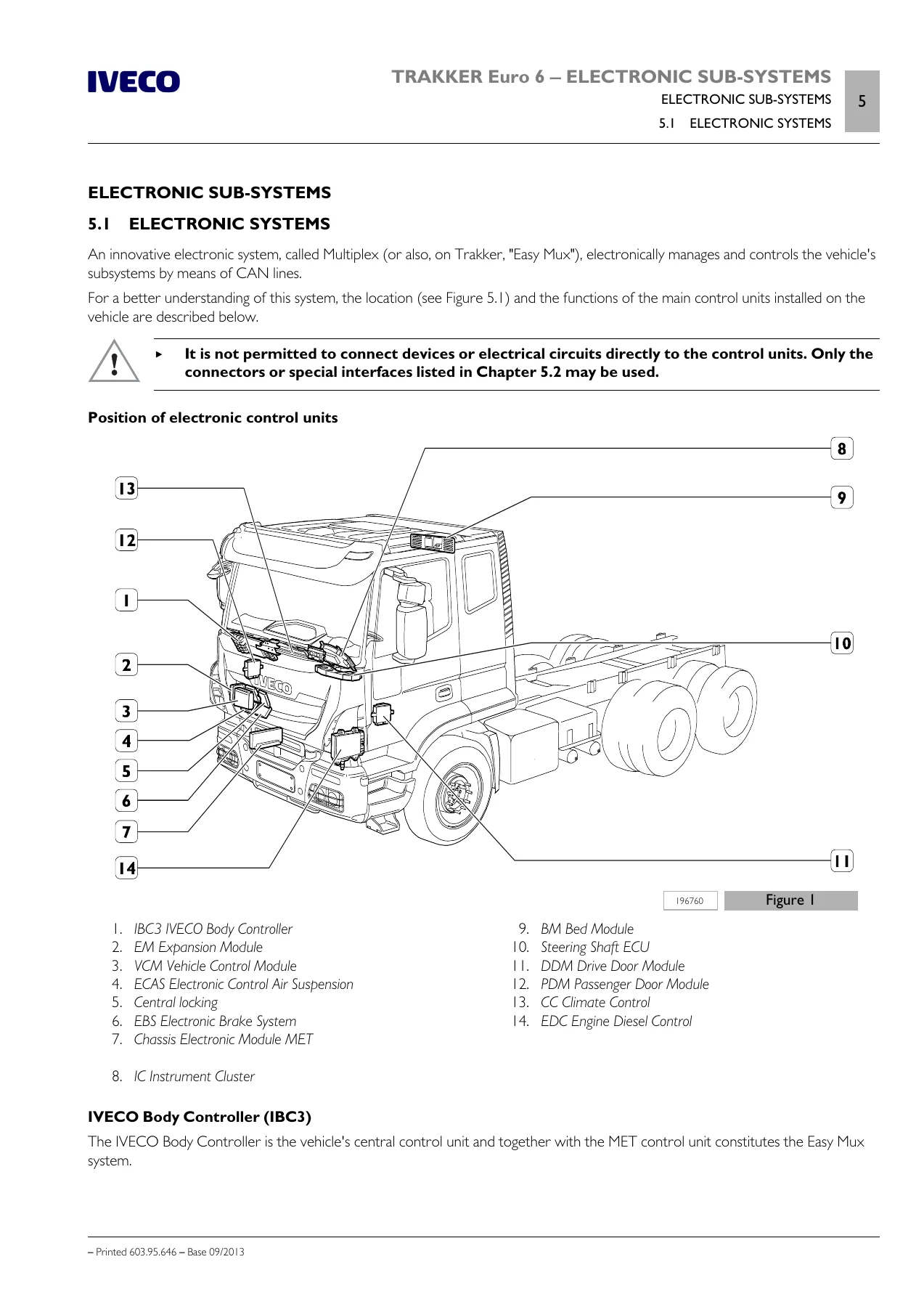
For the electrical and electronic side, the manual documents the Multiplex (Easy Mux) system, the location and function of the IVECO Body Controller (IBC3), Chassis Electronic Module (MET), Expansion Module (EM) and Vehicle Control Module (VCM), and the bodybuilder connectors ST14A, ST14B, ST40, ST64, ST72, ST77, ST78, ST91, ST92 and ST93. It gives pin-level function tables, maximum loads, wire codes and connection notes, plus the rules for FMS connection, current draws, additional batteries, additional alternators, and the electromagnetic compatibility requirements that added equipment must meet. For anyone installing a crane, tail lift, tipper, refrigeration unit or telematics device, this section tells you where to take power, where to take ground, and what not to touch.
Why It Matters
Bodybuilding a Trakker Euro 6 involves cutting and drilling a high-strength steel chassis, altering the wheelbase, adding axles, welding reinforcements, tapping into a CAN-based electrical architecture, and potentially disturbing an AdBlue system that is sensitive to contamination and freezing. Each of those operations has a correct method and a set of limits. The manual provides them. It also provides the legal and approval context: multi-stage approval under Directive 2007/46/EC, ADR requirements for hazardous materials transport, ECE regulations on braking and stability, and the national laws that apply where the vehicle will be registered. Ignoring these is not just a technical risk; it can make the vehicle non-compliant and unsellable.
The manual is equally useful for bodybuilders who need to verify that an existing conversion is correct, or who are taking over a project started by someone else. The dimension tables, material specifications, torque values and connection rules give a benchmark against which any modification can be checked.
Delivery
IMAGES PREVIEW
The Iveco Trakker Euro 6 Bodybuilders Instructions Manual is delivered as an instant PDF download. No shipping, no waiting. The file can be opened on any device – workshop PC, laptop, tablet or phone – and specific pages can be printed for use at the vehicle. Whether you are planning a wheelbase change, fitting a crane, wiring a PTO, installing a tipper body, or routing AdBlue pipes, having the manufacturer’s instructions on hand means the job is done to the correct specification the first time.
Reviews
There are no reviews yet.