
Iveco Trakker Euro 6 Bodybuilder Instructions Manual 2017 – 603.95.646 PDF
Original price was: $39.95.$23.95Current price is: $23.95.
Complete IVECO bodybuilder instructions for the Trakker Euro 6 range. Covers chassis interventions, superstructure applications, power take-offs, electronic sub-systems and the AdBlue/SCRT system. Publication 603.95.646, 2nd edition, December 2017.
Description
Iveco Trakker Euro 6 Bodybuilder Instructions Manual 2017
This is the complete Iveco Trakker Euro 6 Bodybuilder Instructions publication 603.95.646, second edition dated December 2017, issued by IVECO S.p.A. Homologation, Technical Application & Regulation in Torino, Italy. It is the working reference for specialist bodybuilders, converters and workshop engineers who carry out transformation and fitting work on the Trakker Euro 6 chassis range. Every intervention described is one that IVECO has deliberated, approved and tested, so the instructions here reflect the company’s own requirements rather than generic conversion practice.
If you are building, fitting or modifying a Trakker chassis — whether it is a tipper, a crane truck, a tanker, a concrete mixer, a roll-off, a fifth-wheel tractor or any other superstructure — this Iveco Trakker Euro 6 Bodybuilder Instructions Manual 2017 sets out the technical envelope you must stay inside to keep the vehicle functional, safe and within warranty.
File Details
- Manual type: Bodybuilder instructions / guidelines for transformation and fitting
- Brand: IVECO S.p.A.
- Model range: Trakker Euro 6
- Document number: 603.95.646
- Edition: 2nd edition
- Publication date: December 2017
- Language: English
- Page count: 208 pages
- File format: PDF
Chapters Covered in the Iveco Trakker Euro 6 Bodybuilder Instructions Manual 2017
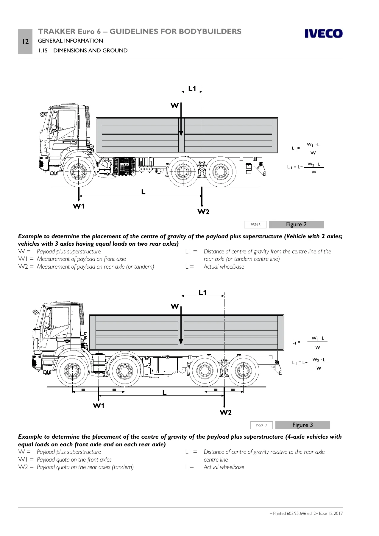
The document is organised into six sections that run from legal and dimensional groundwork all the way through to the AdBlue and SCRT system. Section 1 deals with the ground rules: the scope of the guidelines, the technical documentation available electronically, IVECO authorisation and when it is required, authorisation requests, responsibilities, legislative requirements, multi-stage type approval, warranties, quality system management, accident prevention, choice of materials from an ecology and recycling angle, and vehicle management on the part of the bodybuilder. It also covers vehicle names and commercial naming conventions, dimensions and ground clearance, determination of the centre of gravity of the superstructure and payload, permitted masses, and instructions for proper functioning of vehicle parts and accessibility.
- Section 1 – General Information: scope of the guidelines, electronically available technical documentation, IVECO authorisation, authorisation request, responsibilities, legislative requirements, multi-stage type approval (EU, Switzerland, Turkey), warranties, quality system management, accident prevention, choice of materials (ecology/recycling), vehicle management by the bodybuilder, vehicle names, trademarks and symbols, dimensions and ground, respect of permitted masses, accessibility of vehicle parts, access to the exhaust system, distance from muffler
- Section 2 – Chassis Interventions: general chassis modification standards, material characteristics for chassis modifications, stresses on the chassis, drills on the chassis, hole position and size, screws and nuts, welds, sealing holes by welding, rust and paint protection, wheelbase modification, rear overhang modification, installing the tow hook, assembling an additional axle, gearbox modification, modifying the engine air intake and exhaust systems, work on the engine cooling system, installing an additional heating system, installing an air conditioning system, work on the cab, changing tyre size, work on the braking system, electrical system current interventions and draws, part relocation and anchorage of additional units and equipment, transport of hazardous materials (ADR), installing a retarder, rear under-run protection (RUP), rear mudguards and wheel arches, rain flap, side protections
- Section 3 – Applications of Superstructures: construction of the subframe, material and sizing of profiles, elements making up the subframe, longitudinal profiles and cross members, connection between chassis and subframe, choosing the type of connection, connection characteristics, connection with brackets, connections with greater elasticity, connections with clevis fasteners or clamps, connection with longitudinal and transverse sealing plates (rigid junction), mixed connection, container application, fixed bodies, tipping bodies, heavy-duty services, light-duty services, roll-off containers, tractor for semi-trailer, fifth wheel, fifth wheel advancement, tractor and semi-trailer combination, fifth wheel supporting structure, transport of inseparable materials (trailer trucks), installation of tanks and loose material containers, installing a crane, crane behind cab, cranes on rear overhang, removable cranes, vehicles for council, fire service and special uses, front installation of snow plough attachments, application of a winch, concrete mixer installation, concrete mixer outfitting with EuroTronic II gearbox, interchangeable outfits
- Section 4 – Power Take-Offs: general specifications, PTO from gearbox, PTO from transfer box, PTO from drive line, PTO from engine (torque PTO from front of engine, torque PTO from rear of engine, Multipower PTO on engine flywheel, PTO from camshaft gearing), PTO management, definitions, functional sequence, PTO switch, PTO modes, status of number of revs, standard configurations, no PTO installed or PTO predisposition, PTO Multipower, PTO manual gearbox with electric engagement, engine PTO, PTO Eurotronic 2 gearbox, PTO transfer box, expansion module (EM)
- Section 5 – Electronic Sub-Systems: electronic systems, bodybuilder connectors, connectors in cab (ST14A, ST14B, ST40, 72072A, 72072B, 72072C), connectors on chassis (ST64, 72072D, ST91, ST92, ST93), FMS (Fleet Management System), electronic control units, wiring harness length, disconnecting and repositioning electronic control units, electrical system, precautions for work on the system and on the chassis, ground points, electromagnetic compatibility, receiver-transmission systems (CB 27 MHz and 2 m band 144 MHz, GSM/PCS/UMTS and TETRA/TETRAPOL, GPS reception and satellite navigation), additional equipment, additional batteries, additional alternators, additional electrical units, current draws, general battery switch, main power contactor, voltage reducer, Maxifuse and Megafuse fuses, additional circuits, modifying wheelbase and overhang, connector ST14E, side marker lamp installation, trailer connectors, fuses and relays
- Section 6 – AdBlue and SCRT System: general information, the nitrogen oxide catalytic reduction principle, instructions, AdBlue tank, moving AdBlue system components, moving the tank, moving the muffler, interventions on the wiring and AdBlue and water pipes
Across those six sections, the Iveco Trakker Euro 6 Bodybuilder Instructions Manual 2017 gives a converter the complete technical picture of what the chassis will tolerate. It opens with the legal and warranty framework — the multi-stage type approval obligations that apply to vehicles registered in the EU, Switzerland and Turkey, and the collaboration contract that a bodybuilder must sign before launching that process. It then moves into the physical limits of the chassis: how to weigh it, how to determine the centre of gravity of the payload plus superstructure, how to keep the permitted masses and the front-axle minimum load within limits, and how to keep accessibility to components that need service.
From there the manual turns to the actual metalwork. The chassis intervention section lays down what is and is not permitted — welding is forbidden on the supporting structures except in the specific cases described, drilling must use factory holes where possible, and any new holes have to be in the upright rib of the side member, deburred, bored, and positioned away from spring supports and section changes. There are definite rules on hole diameters, spacing, offset patterns and edge distances. Screws and nuts have to be class 8.8 or 10.9 as appropriate, with anti-unscrewing systems, and safety components must not reuse the same screws after removal.
The wheelbase and rear overhang chapters are extremely practical: how to align the chassis, where to make reference punch marks, how to check the diagonals over a 1500 mm span, how to cut and bevel the side members at 60 degrees, how to apply corner reinforcements, and when additional crossbars are required (for elongations over 600 mm, and where cross-member spacing would otherwise exceed 1000–1200 mm). The same treatment is given to installing a tow hook — including the D-value formula for conventional trailers and the Dc/V formulas for centre-axle trailers — and to fitting an additional axle, which requires IVECO approval because it touches brakes, pneumatics, wiring and electronics.
Section 3 is where the superstructure work lives. The Iveco Trakker Euro 6 Bodybuilder Instructions Manual 2017 explains the purpose of the subframe, the material grades to use (Fe 360D, Fe E420, Fe 510D and their European/German/UK equivalents), and how to size C-section profiles against section modulus tables that run from Wx 16 cm³ up to 480 cm³. It covers longitudinal profile tapering at 30 degrees, the transition from boxed to open sections, cross-member bracing, and stiffening methods for tipping bodies, concrete mixers, cranes on rear overhang and other high-centre-of-gravity applications.
Then comes the connection itself. The manual distinguishes elastic connections — brackets, clevis fasteners, coil springs, rubber blocks — from rigid, shear-resistant connections made with longitudinal and transverse sealing plates, and explains when each is appropriate. Elastic connections let the chassis and subframe work in parallel with each taking a share of the bending moment proportional to its moment of inertia; rigid connections let you treat the two profiles as a single resistant section, which is what you want for tippers, cranes and other high-load bodies. There is also a worked stress-calculation example for an elastic connection using a 250×70×5 mm chassis section against a 140×70×7 mm subframe.
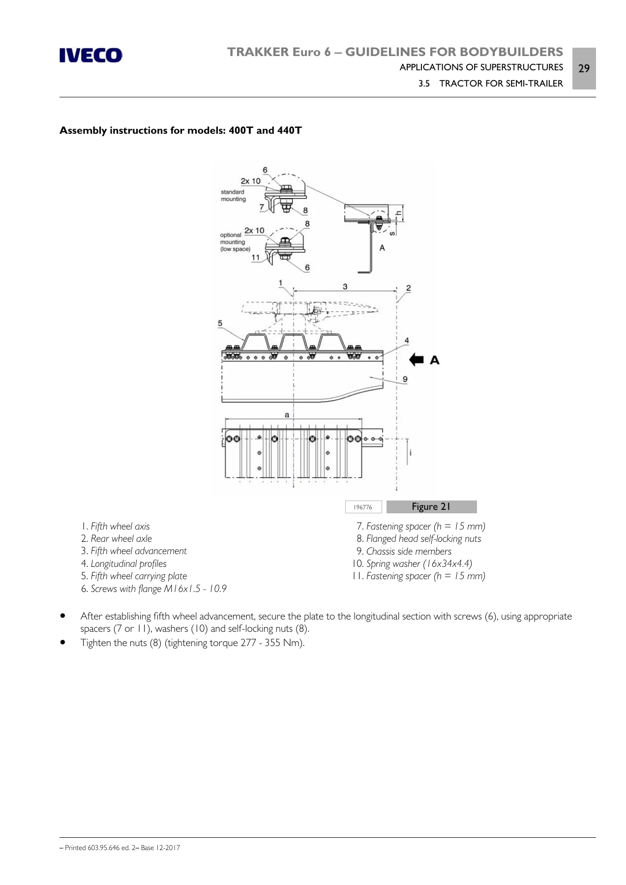
Container application gets its own detailed treatment: fixed bodies, tipping bodies (rear and three-sided), heavy-duty and light-duty services, roll-off containers, and the distance rules that keep the tipping hinge near the rear suspension support. There are specific figures for leaf-spring and air-suspension vehicles — tipping hinge placement against rear support or tandem centre line, and the recommendation to deflate air springs completely during tipping. Fifth-wheel tractor conversion is covered with the supporting structure requirements, the plate and spacer combinations, and the tightening torque of 277–355 Nm for the M16x1.5 flanged nuts. Crane installation is broken down into crane behind cab and cranes on rear overhang, with the subframe extension requirement (never less than 35% of the wheelbase), box-section and bracing zones, and the shear-resistant plate spacing rule of 700 mm maximum.
Section 4 takes on power take-offs in depth. It lists the possible take-off points — gearbox, driveline, transfer box, front of engine, rear of engine — and gives torque and ratio data for the specific gearboxes used in the Trakker Euro 6 range, including the 16 S 1830 TO, 16 S 2230 TO, 12 AS 2330 TO and 16 AS 2630 TO. The Multipower PTO on the engine flywheel is documented with its 1.29 ratio, 900 Nm maximum torque, ISO 7646-120×8×10 output flange and 70 kg weight. The PTO management chapter explains how the Expansion Module and Vehicle Control Module handle activation, the priority order between PTO 1, 2 and 3 (PTO 3 highest, PTO 1 lowest), the functional sequence from switch request through to intermediate speed control, and the programmable timers for engagement, de-engagement and shut-off monitoring.
Section 5 is the electronics section, and for anyone fitting equipment to a Trakker Euro 6 it is essential reading. It documents the Easy Mux (Multiplex) system, the IVECO Body Controller (IBC3), the Chassis Electronic Module (MET), the Vehicle Control Module (VCM) and the Expansion Module (EM), and then walks through every bodybuilder connector. The standard ST14A 21-pin connector pinout is laid out in full: engine start and stop, service brake, vehicle standstill, parking brake, vehicle speed pulse, engine status, gearbox neutral, reverse gear, K15, cruise control Set+/Set−/Off/Resume, CC driver/bodybuilder selection, ground, the three PTO switch inputs and K30. The optional 72072A, 72072B, 72072C and 72072D connectors are covered with their bodybuilder enable input, emergency signal, gearbox-in-neutral request, external stop brake request, refuse packer step switch, light management module outputs, parking brake warning, brake lights, chassis ready signal, low accelerator pedal idle switch, at-least-one-PTO-engaged output, and the analogue fluid level, pressure and temperature inputs. The chassis connectors ST91, ST92 and ST93 for PTO 1, 2 and 3 give feedback, solenoid activation, pressure switch and ground.
The electrical system chapter also covers ground points and why standardised points must not be used for engine or chassis ground, the star-formation rule for negative leads, shielding practice for signal cables, electromagnetic compatibility limits (50 V/m for secondary-function devices, 100 V/m for primary-function devices across 20 MHz to 2 GHz), the additional battery and additional alternator wiring, the voltage reducer’s 20 A limit, and the cable and fuse selection table that runs from 0.5 mm²/5 A up to 50 mm²/150 A. Receiver-transmission system installation — CB, GSM, TETRA, GPS — is documented with antenna placement, ROS/SWR values, and minimum separation distances.
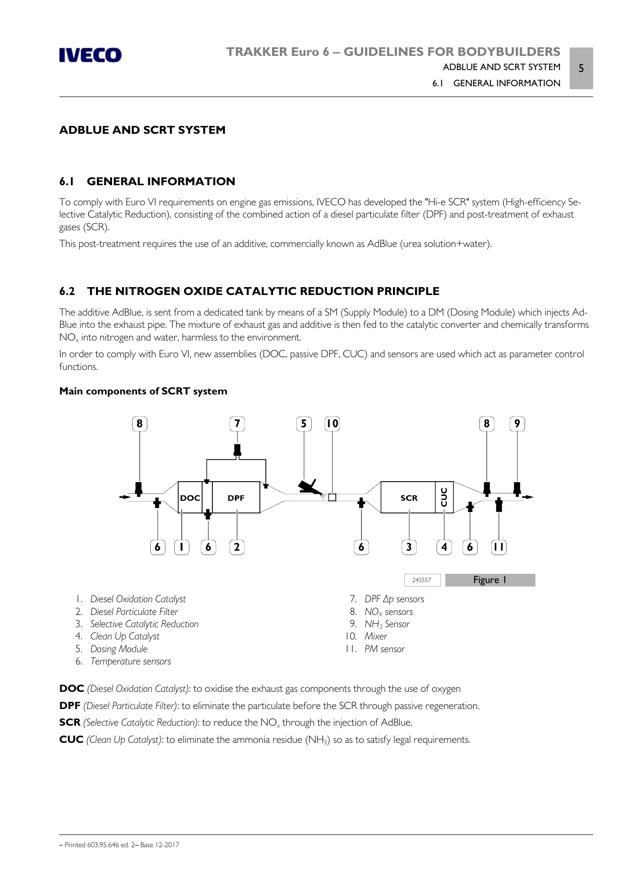
Section 6 closes the manual with the AdBlue and SCRT system. It explains the Hi-e SCR architecture: DOC, passive DPF, SCR and CUC, with the Supply Module and Dosing Module locations. It sets out the rules for moving the AdBlue tank vertically and horizontally (pipe between SM and DM must not exceed 5035 mm), for moving the muffler (up to 100 mm height increase, minimum 80 mm clearance above), and for intervening on the wiring and AdBlue/water pipes — including which cables may be lengthened (temperature, AdBlue heater, AdBlue level sensors) and the explicit prohibition on altering the NOx sensor cable length.
What This Manual Lets You Do
With the Iveco Trakker Euro 6 Bodybuilder Instructions Manual 2017 on hand you can plan and execute a conversion against IVECO’s own published limits instead of guessing. That means knowing before you cut whether a wheelbase change needs approval, how much rear overhang elongation is allowed without additional crossbars, what subframe section modulus a given body and front-axle load requires, where a crane subframe must be boxed and braced, and which PTO the gearbox can accept with what torque.
The manual matters because the alternative is guesswork on a chassis where the wrong weld, the wrong hole position, the wrong subframe section or the wrong AdBlue pipe length can void the vehicle warranty, fail a type approval inspection, or create a safety problem that only shows up loaded and moving. IVECO states plainly that faults or defects caused by failure to comply with these guidelines are not covered by the guarantee on the chassis or its mechanical units. Having the document means you can stay on the right side of that line, and you can show the competent authority exactly which instruction your work follows when approval is required.
You also get the electronic interface detail that makes modern bodybuilder work possible — the pinouts, the bodybuilder enable logic, the CANopen gateway connectors, the PTO priority order — which is the difference between a clean installation and a truck full of fault codes.
Delivery
IMAGES PREVIEW
The Iveco Trakker Euro 6 Bodybuilder Instructions Manual 2017 is delivered as an instant PDF download. There is no shipping, no waiting, no physical book to lose. The file opens on any device — laptop, tablet or phone — and every page can be printed if you prefer a paper copy in the workshop. Search, bookmark and print to your own workflow. Buy once and the reference is yours for the life of the project.



Reviews
There are no reviews yet.