★ TRUSTED BY 321,897+ PROFESSIONALS WORLDWIDE
🏢
Trusted Business
Verified & Licensed
🛡️
Virus Free Files
100% Safe Downloads
🔒
Secure Payment
SSL Protected
Instant Delivery
Available Immediately
Sale!

2017-2020 Navistar International HX Series Technician Service and Diagnostic Manual – PDF

Original price was: $49.95.Current price is: $27.95.

Official factory-level technician service and diagnostic manual for 2017-2020 Navistar International HX515, HX520, HX615, and HX620 trucks. Covers engine, electrical, brakes, HVAC, and drivetrain systems with detailed procedures.

Instant PDF Download
Available immediately
💾
Save to Your Device
Download & keep forever
🛡️
Antivirus Scanned
100% virus-free
🌍
Trusted Worldwide
175,000+ customers

Description

Complete Factory Service & Diagnostic Information for International HX Series Trucks

This is the comprehensive 2017-2020 Navistar International HX Series Technician Service and Diagnostic Manual, a factory-level resource designed for professional technicians. This manual provides the exact specifications, procedures, and diagnostic routines used by authorized service centers to maintain and repair the HX515, HX520, HX615, and HX620 models. It is an essential tool for anyone servicing these heavy-duty vocational trucks, covering the wide range of systems and components that make up the vehicle.

File Details

  • Manual Type: Factory Technician Service and Diagnostic Manual
  • Applicable Brands & Models: Navistar International HX515, HX520, HX615, HX620 (2017-2020)
  • Language: English
  • Page Count: 1,050+ Pages
  • File Format: PDF

What This Manual Contains

This manual is structured to provide a logical and systematic approach to vehicle diagnosis and repair. It is divided into major sections covering the entire truck, from the front bumper to the rear wheels. The depth of information makes it suitable for a wide range of tasks, from routine maintenance to complex troubleshooting of electronic control systems.

IMAGES PREVIEW

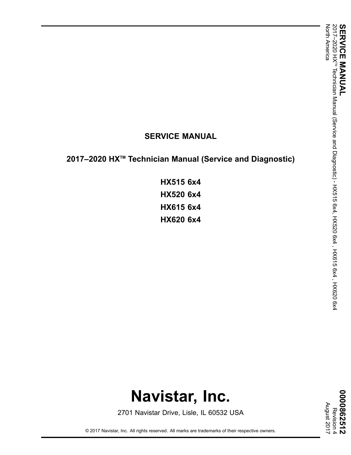
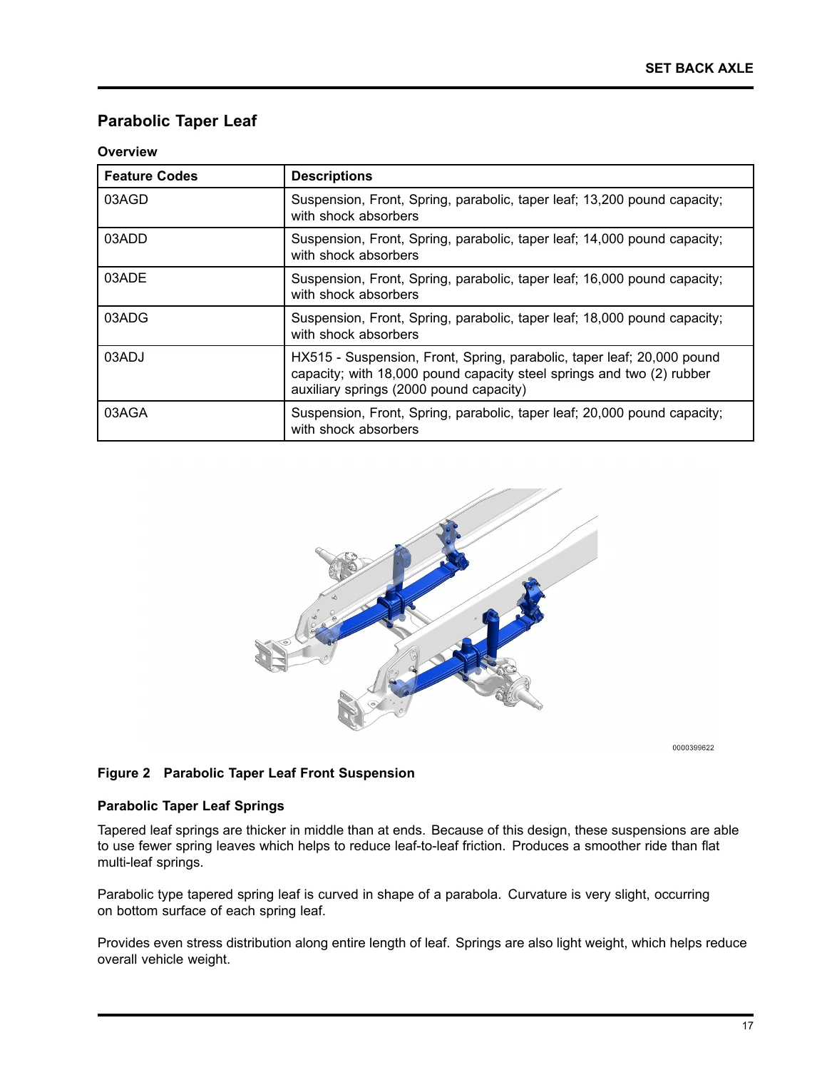
2017-2020 Navistar International HX Series Technician Service and Diagnostic Manual - PDF — PDF page 1 preview
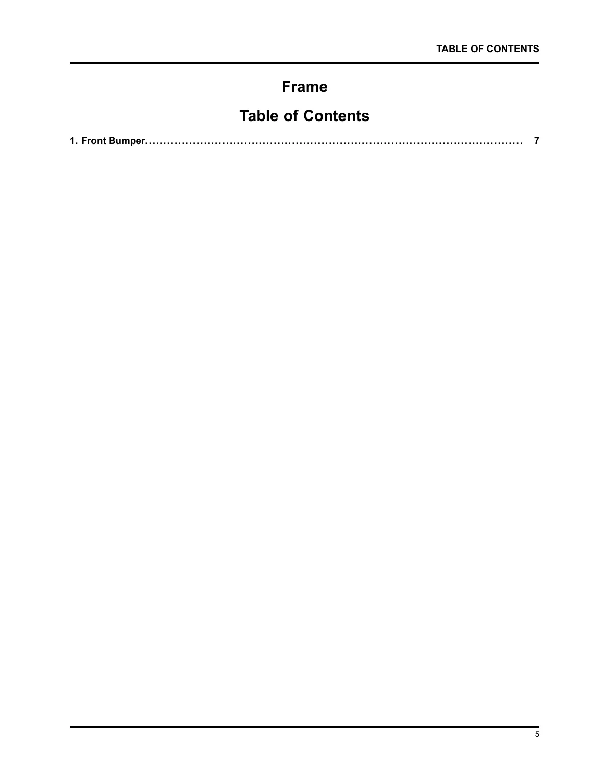
2017-2020 Navistar International HX Series Technician Service and Diagnostic Manual - PDF — PDF page 9 preview
2017-2020 Navistar International HX Series Technician Service and Diagnostic Manual - PDF — PDF page 21 preview

The core of the manual begins with extensive diagnostic procedures for the 12-volt electrical system, covering the battery, CAN systems, starting and charging circuits, and comprehensive troubleshooting trees for ‘no start’ and charging system faults. A significant portion is dedicated to the aftertreatment system, including the DPF, SCR, and DEF components, with specific guidance on regeneration and switch operation.

  • Air Brakes: Detailed coverage of Bendix anti-lock brake systems (ABS), including EC-80 controllers, modulator valves, wheel speed sensors, and electronic stability control (ESP).
  • Steering: Comprehensive chapters on the tilting/telescoping steering column, clock spring, and Sheppard M-Series integral power steering gears.
  • Driveline: Vibration troubleshooting procedures, driveshaft inspection, and universal joint service for 6×4 and 8×6 configurations.
  • Engine & Exhaust: Operation and troubleshooting of the engine compression brake, including the Jacobs system for N13 engines and Cummins Interbrake. It also details the removal and installation of the switchback horizontal/vertical aftertreatment systems, the DEF dosing valve, and related components.
  • Electrical & Lighting: In-depth diagnostic guides for the 12-volt system, covering the Battery Box, Battery Disconnect Switch, CAN Systems, Starting and Charging System, and detailed symptom-based troubleshooting for lighting systems (headlights, fog lights, turn/brake lights, park/marker lights).
  • HVAC System: Comprehensive coverage of the Blend-Air system, including blower motor control, compressor clutch control, high and low-side refrigerant pressure testing, and diagnostics for the APADS system.
  • Transmission: Information on Allison Automatic Transmissions, including push-button shift controls, PTO controls, and troubleshooting procedures for powers, grounds, and data link.
  • Windshield Wiper System: Step-by-step diagnostic procedures for wiper inputs, speeds, relays, and the washer pump, complete with pin-point tests and fault code diagnostics.
  • Collision Avoidance Systems: Detailed service and adjustment information for Bendix Wingman Advanced, including radar sensor removal, installation, and adjustment.

Complete PDF Bookmark Tree

Complete Bookmarks

The complete bookmarks in the “2017-2020 Navistar International HX Series Technician Service and Diagnostic Manual – PDF” are as follows:

tocp. 3
Table of Contentsp. 3
Safety Terminologyp. 6
Safety Instructionsp. 6
Work Areap. 6
Safety Equipmentp. 6
Protective Measuresp. 6
Vehiclep. 6
Enginep. 7
Fire Preventionp. 7
Batteriesp. 7
Compressed Airp. 7
Toolsp. 7
Fluids Under Pressurep. 8
Fuelp. 8
Removal of Tools, Parts, and Equipmentp. 8
Framep. 9
1. Front Bumperp. 11
Overviewp. 11
Front Axlep. 13
1. Front Axlesp. 15
Overviewp. 15
Front Suspensionp. 17
1. Set Back Axlep. 19
Multi-leaf Springsp. 19
Overviewp. 19
Parabolic Taper Leafp. 21
Overviewp. 21
Parabolic Taper Leaf Springsp. 21
Increased Capacity Parabolic Taper Leaf Springsp. 22
Front Suspension Rubber Auxiliary Springsp. 22
Multi-leaf Slipper Type with Torque Rodp. 23
Overviewp. 23
2. Set Forward Axlep. 24
Multi-leaf Springp. 24
Overviewp. 24
Parabolic Taper Leafp. 25
Overviewp. 25
Increased Capacity Parabolic Taper Leaf Springsp. 26
Front Suspension Rubber Auxiliary Springsp. 26
3. Torquep. 27
Brakesp. 29
1. Air Brakesp. 31
Bendix® Anti-lock Brake System (ABS)p. 31
Overviewp. 31
Bendix® EC‑80™p. 35
Overviewp. 35
Bendix® ESP® EC‑80™ Controller Service Informationp. 37
Overviewp. 37
Removalp. 38
Installationp. 39
Bendix® EC‑80™ ABS/ATC Controller Service Informationp. 40
Overviewp. 40
Modulator Valve M-40p. 41
Removalp. 41
Overviewp. 41
Special Toolsp. 41
Equipment Conditionsp. 41
Removal Procedurep. 42
Follow-On Procedurep. 42
Installationp. 43
Overviewp. 43
Special Toolsp. 43
Torque Specificationsp. 43
Equipment Conditionsp. 43
Installation Procedurep. 44
Follow-On Procedurep. 44
Steering Angle Sensorp. 45
Removalp. 45
Installationp. 46
Wheel Speed Sensor WS-24p. 47
Removalp. 47
Overviewp. 47
Special Toolsp. 47
Equipment Conditionsp. 47
Removal Procedurep. 48
Follow-On Procedurep. 48
Installationp. 49
Overviewp. 49
Special Toolsp. 49
Torque Specificationsp. 49
Equipment Conditionsp. 49
Installation Procedurep. 50
Follow-On Procedurep. 50
Yaw Rate Sensorp. 51
Removalp. 51
Overviewp. 51
Special Toolsp. 51
Equipment Conditionsp. 51
Removal Procedurep. 52
Follow-On Procedurep. 52
Installationp. 53
Overviewp. 53
Special Toolsp. 53
Equipment Conditionsp. 53
Installation Procedurep. 54
Follow-On Procedurep. 54
2. Air Compressorp. 55
Engine Mounted Air Compressorp. 55
Overviewp. 55
Bendix® BA-921® 15.9 Cubic Feet per Minute (CFM) Single Cylinderp. 56
Overviewp. 56
Service Informationp. 56
Cummins® 18.7 Cubic Feet per Minute (CFM) Air Compressorp. 57
Overviewp. 57
Service Informationp. 57
Knorr-Bremse® LP-720™ DLU 31.8 Cubic Feet per Minute (CFM) Dual Cylinder Air Compressorp. 58
Overviewp. 58
Service Informationp. 58
Yoosung® Air Compressor 21.0 Cubic Feet per Minute (CFM) Air Compressorp. 59
Overviewp. 59
Service Informationp. 59
3. Air Dryersp. 60
Overviewp. 60
Bendix® AD-9™ Air Dryer with Heaterp. 61
Overviewp. 61
Service Informationp. 61
Bendix® AD-IP™ Integral Purge Air Dryerp. 62
Overviewp. 62
Service Informationp. 62
Meritor WABCO System Saver 1200 Air Dryer with Heaterp. 63
Overviewp. 63
Service Informationp. 63
4. Brakesp. 64
Air Dual Brake System for Straight Trucksp. 64
Overviewp. 64
Air Dual Brake System for Tractorsp. 65
Overviewp. 65
Steeringp. 67
1. Steering Columnp. 69
Tilting and Telescoping Steering Columnp. 69
Overviewp. 69
Steering Wheelp. 70
Overviewp. 70
Clock Springp. 71
Overviewp. 71
Steering Columnp. 72
Overviewp. 72
Descriptionp. 72
Maintenancep. 73
End Yoke Pinch Boltsp. 73
Lubricationp. 73
Steering Wheel Alignmentp. 73
Operationp. 74
Tiltp. 74
Telescopep. 74
2. Steering Gearp. 75
Sheppard M-Series Integral Power Steering Gearp. 75
Overviewp. 75
Sheppard M-100/HD94 Dual Powerp. 75
Overviewp. 75
Sheppard M-100/M-80 Dual Powerp. 75
Overviewp. 75
Sheppard M-110/M-80 Dual Powerp. 76
Overviewp. 76
Sheppard M-100 Powerp. 76
Overviewp. 76
Service Informationp. 76
Sheppard Service Manualp. 76
Torque Chartp. 76
Drivelinesp. 77
1. Drivelinep. 79
Overviewp. 79
Driveshaftp. 79
Overviewp. 79
Inner-Axle Shaftp. 80
Overviewp. 80
Service Informationp. 80
Driveline Vibration and Troubleshooting Proceduresp. 81
Inspect and Measure Drivelinep. 81
Overviewp. 81
Required Toolsp. 81
Equipment Conditionsp. 81
Troubleshooting Driveline Vibrationp. 81
Exhaustp. 83
1. Aftertreatmentp. 85
Aftertreatment with Special Temperature Control For Stationary Applicationsp. 85
Overviewp. 85
2. Engine Compression Brakep. 85
Cummins® Interbrakep. 85
Overviewp. 85
Jacobs for N13 Enginesp. 86
Overviewp. 86
3. Exhaust Systemp. 88
Switchback Horizontal Aftertreatment and Dual Vertical Tail Pipesp. 88
Overviewp. 88
Horizontal / Horizontal Exhaust System – Remove and Installp. 89
Equipment Conditionsp. 89
Removep. 90
Installp. 92
Diesel Exhaust Fluid (DEF) Dosing Valve – Remove and Installp. 94
Equipment Conditionsp. 94
Removep. 95
Installp. 96
Decomposition Reactor Tube – Remove and Installp. 97
Equipment Conditionsp. 97
Removep. 98
Installp. 99
Switchback Horizontal Aftertreatment and Single Vertical Tail Pipesp. 100
Overviewp. 100
Switchback Vertical Aftertreatment Device with Dual Cansp. 101
Overviewp. 101
Vertical / Vertical Exhaust System – Remove and Installp. 102
Equipment Conditionsp. 102
Removep. 103
Installp. 104
Diesel Particulate Filter (DPF) or Selective Catalyst Reduction (SCR) Heat Shield – Remove and Installp. 105
Equipment Conditionsp. 105
Removep. 106
Installp. 107
Power Distribution Module (PDM) – Remove and Installp. 108
Equipment Conditionsp. 108
Removep. 109
Installp. 110
Aftertreatment Control Module (ACM) – Remove and Installp. 111
Equipment Conditionsp. 111
Removep. 112
Installp. 113
4. Torquep. 114
Electrical / Softwarep. 115
1. How to Use Diamond Logic® Builder (DLB)p. 119
Interface Device Selectionp. 119
Connecting Diamond Logic® Builder Softwarep. 121
Activating Diagnostic modep. 122
Making a Session with Diamond Logic® Builderp. 123
2. 12 Volt Electrical Systemp. 124
Battery Boxp. 124
Overviewp. 124
Battery Disconnectp. 125
Special Toolsp. 125
Torque Specificationsp. 125
Equipment Conditionsp. 125
Disconnect Procedurep. 126
Follow-On Procedurep. 126
Battery Reconnectp. 127
Special Toolsp. 127
Torque Specificationsp. 127
Equipment Conditionsp. 127
Reconnect Procedurep. 128
Follow-On Procedurep. 128
Battery Disconnect Switchp. 129
CAN Systemsp. 130
Overviewp. 130
Faultsp. 130
Shortp. 130
Terminating Resistor Failurep. 130
Backbone Openp. 130
Node Openp. 131
Testsp. 132
Module Communication Testp. 132
Overviewp. 132
Tools Requiredp. 132
Equipment Conditionp. 132
Test Setupp. 132
Test Procedurep. 133
Follow-On Procedurep. 133
Starting and Charging Systemp. 133
Operational Checkout Procedurep. 134
Starting Systemp. 135
Overviewp. 135
Battery Packp. 135
Starterp. 135
Controlp. 135
Symptom 1: No Click No Crankp. 136
Overviewp. 136
Possible Causesp. 136
Symptom 2: Click No Crankp. 138
Overviewp. 138
Possible Causesp. 138
Symptom 3: Low Cranking Speedp. 139
Overviewp. 139
Possible Causesp. 139
Symptom 4: No Starter Input Signal (Automated Manual Transmission)p. 140
Automated Manual Transmission Starter Input Diagnosticsp. 140
Automated Manual Transmission Starter Input Pinpoint Testsp. 144
Tools Requiredp. 144
Symptom 5: No Starter Input Signal (Automatic Transmission)p. 155
Automatic Transmission Starter Input Pinpoint Testsp. 159
Tools Requiredp. 159
Symptom 6: No Starter Input Signal (Manual Transmission)p. 170
Manual Transmission Starter Input Pinpoint Testsp. 174
Tools Requiredp. 174
Charging Systemp. 185
Overviewp. 185
Overviewp. 185
Battery Packp. 185
Alternatorp. 185
Symptom 7: Battery Gauge Reading Highp. 187
Overviewp. 187
Possible Causesp. 187
Symptom 8: Battery Gauge Reading Low / Fluctuatingp. 188
Overviewp. 188
Possible Causesp. 188
Symptom 9: Low Battery Warning / Alarmp. 190
Overviewp. 190
Possible Causesp. 190
Symptom 10: Repeated Jump Startsp. 191
Overviewp. 191
Possible Causesp. 191
Testsp. 193
Battery Testp. 193
Overviewp. 193
Tools Requiredp. 193
Equipment Conditionp. 193
Test Setupp. 193
Test Procedurep. 193
Expected Outcomep. 194
Follow-On Procedurep. 195
Cable Drop Testp. 196
Overviewp. 196
Tools Requiredp. 196
Equipment Conditionp. 196
Test Setupp. 196
Test Procedurep. 196
Expected Outcomep. 197
Follow-On Procedurep. 197
Electrical System Testp. 198
Overviewp. 198
Tools Requiredp. 198
Equipment Conditionp. 198
Test Setupp. 198
Test Procedurep. 198
Starter System Test Procedurep. 201
Charging System Test Procedurep. 202
Expected Outcomep. 203
Follow-On Procedurep. 203
Manual Engine Bar Testp. 204
Overviewp. 204
Tools Requiredp. 204
Equipment Conditionp. 204
Test Setupp. 204
Test Procedurep. 204
Expected Outcomep. 204
Follow-On Procedurep. 204
Parasitic Draw Testp. 205
Overviewp. 205
Tools Requiredp. 205
Equipment Conditionp. 205
Test Setupp. 205
Test Procedurep. 206
Expected Outcomep. 208
Follow-On Procedurep. 208
Starter Control Circuit Testp. 209
Overviewp. 209
Tools Requiredp. 209
Equipment Conditionp. 209
Test Setupp. 209
Test Procedurep. 209
Expected Outcomep. 209
Follow-On Procedurep. 210
Inspectionsp. 211
Electrical System Inspectionp. 211
Overviewp. 211
Tools Requiredp. 211
Equipment Conditionp. 211
Inspection Procedurep. 211
Expected Outcomep. 211
Follow-On Procedurep. 211
Ring Gear Inspectionp. 212
Overviewp. 212
Tools Requiredp. 212
Equipment Conditionp. 212
Inspection Procedurep. 212
Expected Outcomep. 213
Follow-On Procedurep. 213
3. Aftertreatmentp. 214
Diesel Particulate Filter (DPF)p. 214
Regeneration Inhibit Switchp. 214
Overviewp. 214
Parked Regeneration Switchp. 218
Overviewp. 218
HEST Monitoringp. 221
Overviewp. 221
4. Brakesp. 224
Air — Anti-Lock Brake (ABS) Systemp. 224
Bendix®p. 224
Overviewp. 224
Inputsp. 227
Outputsp. 228
Operational Checkout Procedurep. 230
Overviewp. 230
Symptom 1: ABS Module Loss of Communicationp. 231
Overviewp. 231
Fault Factsp. 231
Tools Requiredp. 231
Possible Causesp. 231
Air — Automatic Traction Control Systemp. 234
Bendix®p. 234
Overviewp. 234
Inputsp. 235
Outputsp. 236
Air — Electronic Stability Control (ESC) Systemp. 237
Bendix®p. 237
Overviewp. 237
Inputsp. 238
Outputsp. 239
5. Chassis Body Building Wiringp. 241
Overviewp. 241
Operational Checkout Procedurep. 244
Overviewp. 244
Tail and Marker Diagnosticsp. 247
Overviewp. 247
Left Turn Light Diagnosticsp. 250
Overviewp. 250
Right Turn Light Diagnosticsp. 253
Overviewp. 253
Back Up Light Diagnosticsp. 256
Overviewp. 256
Accessory Diagnosticsp. 258
Overviewp. 258
Stop Light Diagnosticsp. 260
Overviewp. 260
Trailer Lighting Diagnosticsp. 263
Overviewp. 263
Remote Cruise Control Connectionp. 269
Overviewp. 269
6. Collision Avoidance Systemsp. 270
Collision Mitigation Systemp. 270
Bendix® Wingman® Advanced™p. 270
Overviewp. 270
Adaptive Cruise Control (ACC)p. 272
Alertsp. 272
Collision Mitigation Brakingp. 272
Tech Tipsp. 274
Operational Checkout Procedurep. 275
Overviewp. 275
Symptom 1: Radar Sensor Loss of Communicationp. 277
Overviewp. 277
Fault Factsp. 277
Tools Requiredp. 277
Possible Causesp. 277
Radar Sensor Removalp. 280
Special Toolsp. 280
Torque Specificationsp. 280
Equipment Conditionsp. 280
Removal Procedurep. 280
Follow-On Procedurep. 281
Radar Sensor Installationp. 282
Special Toolsp. 282
Torque Specificationsp. 282
Equipment Conditionsp. 282
Installation Procedurep. 282
Follow-On Procedurep. 283
Radar Sensor Adjustmentp. 284
Special Toolsp. 284
Equipment Conditionsp. 284
Lateral Adjustment Procedurep. 284
Vertical Adjustment Procedurep. 286
Follow-On Procedurep. 288
7. Drivetrainp. 289
Driver Controlled Locking Differentialp. 289
Overviewp. 289
8. HVACp. 293
HVAC Controlp. 293
Compressorp. 294
Condenserp. 294
Receiver/Drierp. 294
HVAC Assemblyp. 295
Evaporator Corep. 295
Thermal Switchp. 295
Expansion Valve and Pressure Switchesp. 296
Air Conditioning Protection and Diagnostic Systems (APADS)p. 298
HVAC Symptom Diagnosticsp. 299
Operational Checkout Procedurep. 300
Overviewp. 300
Blower Not Working Properly for One or More Speedsp. 303
Overviewp. 303
Blower Control position 1 (lowest volume air flow)p. 303
Blower Control position 2p. 303
Blower Control position 3p. 303
Blower Control position 4 (highest volume air flow)p. 303
Possible Causesp. 303
Test Procedurep. 305
Pin-Point Tests – Blower Motor Controlp. 308
HVAC System Air Not Cool After A/C Turned ONp. 310
Overviewp. 310
Fault Factsp. 310
Possible Causesp. 310
HVAC System Air Not Warm After Heat Turned ONp. 314
Overviewp. 314
Possible Causesp. 314
Air Not Flowing Out Correct HVAC Ductsp. 317
Overviewp. 317
Possible Causesp. 317
Tests and Inspectionsp. 323
Blower Speeds Testsp. 323
Overviewp. 323
Tools Requiredp. 323
Equipment Conditionp. 323
Test Setupp. 323
Test Procedurep. 324
Expected Outcomep. 331
Static Refrigerant Pressure Testp. 332
Overviewp. 332
Tools Requiredp. 332
Equipment Conditionp. 332
Test Setupp. 332
Test Procedurep. 333
Expected Outcomep. 333
High and Low Side Refrigerant Pressure Testp. 334
Overviewp. 334
Tools Requiredp. 334
Equipment Conditionp. 334
Test Setupp. 335
Test Procedurep. 335
Expected Outcomep. 336
Gauge Readings Indicating Possible Problemsp. 336
HVAC Air Flow Control Testingp. 337
Overviewp. 337
Tools Requiredp. 337
Equipment Conditionp. 337
Test Setupp. 337
Test Procedurep. 338
Expected Outcomep. 340
Base A/C System Compressor Clutch Control Testingp. 341
Overviewp. 341
Tools Requiredp. 343
Equipment Conditionp. 343
Test Setupp. 343
Test Procedurep. 344
Expected Outcomep. 347
APADS A/C System Compressor Clutch Control Testingp. 348
Overviewp. 348
APADS Compressor Control Rulesp. 349
Tools Requiredp. 349
Equipment Conditionp. 349
Test Setupp. 349
Test Procedurep. 349
Expected Outcomep. 349
A/C Compressor Compression Testp. 350
Overviewp. 350
Tools Requiredp. 350
Equipment Conditionp. 350
Test Procedurep. 350
Expected Outcomep. 350
9. Instruments / Gaugesp. 351
Auxiliary Gauge Packp. 351
Overviewp. 351
Air Application Gaugep. 353
Overviewp. 353
Air Cleaner Restriction Gaugep. 354
Overviewp. 354
Eaton Ultrashift Shifter Gaugep. 355
Overviewp. 355
Manifold Pressure Gaugep. 356
Overviewp. 356
Rear Axle Oil Temperature Gaugep. 357
Overviewp. 357
Rear Suspension Air Pressure Gaugep. 358
Overviewp. 358
Instrument Clusterp. 359
Overviewp. 359
Air Tank Pressure Gaugesp. 362
Overviewp. 362
Coolant Temperature Gaugep. 364
Overviewp. 364
Diesel Exhaust Fluid (DEF) Level Gaugep. 365
Overviewp. 365
Engine Oil Pressure Gaugep. 366
Overviewp. 366
Engine Oil Temperature Gaugep. 367
Overviewp. 367
Fuel Level Gaugep. 368
Overviewp. 368
Speedometerp. 369
Overviewp. 369
Tachometerp. 370
Overviewp. 370
Transmission Oil Temperature Gaugep. 371
Overviewp. 371
Voltmeterp. 372
Overviewp. 372
Park Brake Indicatorp. 373
Overviewp. 373
10. Lighting Systemsp. 374
Turn, Hazard, and Brake Lightsp. 374
Overviewp. 374
Operational Checkout Procedurep. 376
Overviewp. 376
Turn, Hazard or Brake Lights Not Illuminatingp. 378
Overviewp. 378
Fault Factsp. 378
Possible Causesp. 378
Turn and Hazard Lights Input Diagnosticsp. 388
Overviewp. 388
Fault Factsp. 388
Possible Causesp. 388
Fog Lightsp. 395
Overviewp. 395
Fog Lights Not Illuminatingp. 397
Overviewp. 397
Possible Causesp. 397
Pin-Point Test – Fog lights Not illuminatingp. 405
Tools Requiredp. 405
Headlightsp. 407
Overviewp. 407
Operational Checkout Procedurep. 409
Overviewp. 409
Low Beam Headlights Not Illuminatingp. 411
Overviewp. 411
Fault Factsp. 411
Possible Causesp. 411
Pin-Point Test – Low Beam Headlights Not illuminatingp. 417
Tools Requiredp. 417
Low Beam Headlights Illuminate When Not Requestedp. 425
Overviewp. 425
Fault Factsp. 425
Possible Causesp. 425
Pin-Point Test – Low Beam Headlights Illuminate When Not Requestedp. 429
Tools Requiredp. 429
SPN 2653 FMI 5 – Left Low Beam Under Currentp. 432
Overviewp. 432
Associated Faultsp. 432
Fault Factsp. 432
Possible Causesp. 432
Pin-Point Test – SPN 2653 FMI 5p. 434
Tools Requiredp. 434
SPN 2653 FMI 6 – Left Low Beam Short to Groundp. 435
Overviewp. 435
Associated Faultsp. 435
Fault Factsp. 435
Possible Causesp. 435
Pin-Point Test – SPN 2653 FMI 6p. 436
Tools Requiredp. 436
SPN 2655 FMI 5 – Right Low Beam Open Circuitp. 437
Overviewp. 437
Associated Faultsp. 437
Fault Factsp. 437
Possible Causesp. 437
Pin-Point Test – SPN 2655 FMI 5p. 439
Tools Requiredp. 439
SPN 2655 FMI 6 – Right Low Beam Short to Groundp. 440
Overviewp. 440
Associated Faultsp. 440
Fault Factsp. 440
Possible Causesp. 440
Pin-Point Test – SPN 2655 FMI 6p. 441
Tools Requiredp. 441
Operational Checkout Procedurep. 442
Overviewp. 442
High Beam Headlights Not Illuminatingp. 444
Overviewp. 444
Fault Factsp. 444
Possible Causesp. 444
Pin-Point Test – High Beam Headlights Not illuminatingp. 450
Tools Requiredp. 450
High Beam Headlights Illuminate When Not Requestedp. 458
Overviewp. 458
Fault Factsp. 458
Possible Causesp. 458
Pin-Point Test – High Beam Headlights Illuminate When Not Requestedp. 462
Tools Requiredp. 462
Flash-To-Pass Not Illuminating Headlightsp. 465
Overviewp. 465
Fault Factsp. 465
Possible Causesp. 465
Pin-Point Test – Flash-To-Pass Not illuminating Headlightsp. 468
Tools Requiredp. 468
SPN 4011 FMI 5 – Left High Beam Open Circuitp. 470
Overviewp. 470
Associated Faultsp. 470
Fault Factsp. 470
Possible Causesp. 470
Pin-Point Test – SPN 4011 FMI 5p. 472
Tools Requiredp. 472
SPN 4011 FMI 6 – Left High Beam Short to Groundp. 473
Overviewp. 473
Associated Faultsp. 473
Fault Factsp. 473
Possible Causesp. 473
Pin-Point Test – SPN 4011 FMI 6p. 474
Tools Requiredp. 474
SPN 4012 FMI 5 – Right High Beam Open Circuitp. 475
Overviewp. 475
Associated Faultsp. 475
Fault Factsp. 475
Possible Causesp. 475
Pin-Point Test – SPN 4012 FMI 5p. 477
Tools Requiredp. 477
SPN 4012 FMI 6 – Right High Beam Short to Groundp. 478
Overviewp. 478
Associated Faultsp. 478
Fault Factsp. 478
Possible Causesp. 478
Pin-Point Test – SPN 4012 FMI 6p. 479
Tools Requiredp. 479
Brake Switch Inputp. 480
Overviewp. 480
Brake Switch Input Diagnosticsp. 482
Fault Factsp. 482
Possible Causesp. 482
SPN 597 FMI 0 – Brake Switch Reading Above Normalp. 485
Overviewp. 485
Associated Faultsp. 485
Fault Factsp. 485
Possible Causesp. 485
SPN 597 FMI 1 – Brake Switch Reading Below Normal Rangep. 487
Overviewp. 487
Associated Faultsp. 487
Fault Factsp. 487
Possible Causesp. 487
Park / Marker Lightsp. 488
Overviewp. 488
Operational Checkout Procedurep. 490
Overviewp. 490
Park Lights Not Illuminatingp. 492
Overviewp. 492
Fault Factsp. 492
Possible Causesp. 492
Pin-Point Test – Park Lights Not Illuminatingp. 499
Tools Requiredp. 499
Park Lights Illuminate When Not Requestedp. 506
Overviewp. 506
Fault Factsp. 506
Possible Causesp. 506
Pin-Point Test – Park Lights Illuminate When Not Requestedp. 509
Tools Requiredp. 509
SPN 2378 FMI 5 – Park Lights Undercurrentp. 511
Overviewp. 511
Associated Faultsp. 511
Fault Factsp. 511
Possible Causesp. 511
Pin-Point Test – SPN 2378 FMI 5p. 514
Tools Requiredp. 514
SPN 2378 FMI 6 – Park Lights Overcurrentp. 516
Overviewp. 516
Associated Faultsp. 516
Fault Factsp. 516
Possible Causesp. 516
Pin-Point Test – SPN 2378 FMI 6p. 518
Tools Requiredp. 518
Work Lightp. 519
11. Transmissionp. 520
Allison Automatic Transmissionp. 520
Overviewp. 520
Push Button Shift Control (Allison)p. 524
Overviewp. 524
PTO Controls Dash Mountedp. 526
Overviewp. 526
12. Windshield Wiper Systemp. 528
Windshield Wiper Diagnosticsp. 528
Overviewp. 528
Wiper Operationp. 528
Park Operationp. 529
Washer Operationp. 529
Operational Checkout Procedurep. 535
Overviewp. 535
Windshield Wiper Input 0 Not Workingp. 540
Overviewp. 540
Fault Factp. 540
Possible Causesp. 540
Pin-Point Test – Windshield Wiper Input Circuit 0 Not Workingp. 542
Tools Requiredp. 542
Windshield Wiper Input 1 Not Workingp. 546
Overviewp. 546
Fault Factp. 546
Possible Causesp. 546
Pin-Point Test – Windshield Wiper Input 1 Not Workingp. 548
Tools Requiredp. 548
Windshield Wiper Input 2 Not Workingp. 552
Overviewp. 552
Fault Factp. 552
Possible Causesp. 552
Pin-Point Test – Windshield Wiper Input 2 Not Workingp. 554
Tools Requiredp. 554
Windshield Wiper Low Speed Not Workingp. 558
Overviewp. 558
Fault Factsp. 558
Possible Causesp. 558
Pin-Point Test – Windshield Wiper Low Speed Not Functioningp. 562
Tools Requiredp. 562
Windshield Wiper High Speed Not Workingp. 568
Overviewp. 568
Fault Factsp. 568
Possible Causesp. 568
Pin-Point Test – Windshield Wiper High Speed Not Workingp. 572
Tools Requiredp. 572
SPN 2636 FMI 5 – Wiper ON / OFF Relay Under Current or Open Circuitp. 578
Overviewp. 578
Associated Faultsp. 578
Fault Factsp. 578
Possible Causesp. 578
Pin-Point Test – SPN 2636 FMI 5p. 579
Tools Requiredp. 579
SPN 2636 FMI 6 – Wiper ON / OFF Relay Over Currentp. 580
Overviewp. 580
Associated Faultsp. 580
Fault Factsp. 580
Possible Causesp. 580
Pin-Point Test – SPN 2636 FMI 6p. 581
Tools Requiredp. 581
SPN 2637 FMI 5 – Wiper High / Low Relay Under Current or Open Circuitp. 582
Overviewp. 582
Associated Faultsp. 582
Fault Factsp. 582
Possible Causesp. 582
Pin-Point Test – SPN 2637 FMI 5p. 583
Tools Requiredp. 583
SPN 2637 FMI 6 – Wiper High / Low Relay Over Currentp. 584
Overviewp. 584
Associated Faultsp. 584
Fault Factsp. 584
Possible Causesp. 584
Pin-Point Test – SPN 2637 FMI 6p. 585
Tools Requiredp. 585
SPN 4057 FMI 5 – Wiper Motor Under Currentp. 586
Overviewp. 586
Associated Faultsp. 586
Fault Factsp. 586
Possible Causesp. 586
Pin-Point Test – SPN 4057 FMI 5p. 589
Tools Requiredp. 589
SPN 4057 FMI 6 – Wiper Motor Over Currentp. 592
Overviewp. 592
Associated Faultsp. 592
Fault Factsp. 592
Possible Causesp. 592
Pin-Point Test – SPN 4057 FMI 6p. 595
Tools Requiredp. 595
Windshield Washer Pump Not Workingp. 599
Overviewp. 599
Fault Factp. 599
Possible Causesp. 599
Pin-Point Test – Windshield Washer Pump Not Workingp. 601
Tools Requiredp. 601
Windshield Wipers Not Working when Washer Pump Activatedp. 605
Overviewp. 605
Fault Factp. 605
Possible Causesp. 605
Pin-Point Test – Windshield Wipers Not Working when Washer Pump Activatedp. 607
Tools Requiredp. 607
Windshield Washer Pump and Wipers Not Workingp. 608
Overviewp. 608
Fault Factp. 608
Possible Causesp. 608
Pin-Point Test – Windshield Wiper and Washer Pump Not Workingp. 610
Tools Requiredp. 610
Front Endp. 613
1. Bug Deflector/Screenp. 615
Overviewp. 615
2. Fender Extensionsp. 615
Overviewp. 615
Quarter Fenders – Rear Wheelsp. 615
Overviewp. 615
3. Hood/Grillp. 616
Overviewp. 616
Head Lightsp. 617
Head Light Maintenancep. 617
Equipment Conditionsp. 617
Adjustmentp. 618
Head Light Bulb Replacementp. 618
Head Light Assembly – Remove and Installp. 619
Equipment Conditionsp. 619
Removep. 620
Installp. 621
Fifth Wheel and Misc.p. 623
1. Fifth Wheelp. 625
Air Slide ON / OFF Toggle Switchp. 625
Overviewp. 625
Air Slide Fifth Wheelp. 626
Overviewp. 626
Stationary Fifth Wheelp. 628
Overviewp. 628
2. Keysp. 629
Door Lock and Ignition Keysp. 629
Overviewp. 629
Clutchp. 631
1. Clutch Systemp. 633
Clutch Brakep. 633
Overviewp. 633
Hydraulic Clutch Actuation System with Air Assistp. 634
Overviewp. 634
Clutch Pedalp. 634
Master Cylinderp. 635
Reservoirp. 635
Air Assist Servo and Slave Cylinderp. 635
Hydraulic Hosep. 635
Bleeder Valvep. 635
Service Informationp. 635
Master Cylinderp. 636
Equipment Conditionsp. 636
Push Rod Adjustmentp. 637
Clutchp. 638
Overviewp. 638
Eaton® Fuller Solo Clutchp. 640
Eaton® Fuller Soft-Rate 7 Spring Damperp. 641
Eaton® Fuller Vibration Control Technology (VCT) Plus Soft-Rate Damperp. 642
Eaton® Fuller VCT Plus Soft-Rate Damper with Pre-Damperp. 643
Torquep. 644
Enginesp. 645
1. Air Cleanerp. 647
Overviewp. 647
2. Block Heaterp. 649
Overviewp. 649
3. Cold Start Assistp. 650
Either Cold Startp. 650
Overviewp. 650
HX515 and HX615p. 651
HX620p. 651
4. Cooling Systemp. 652
Radiator Systemp. 652
Overviewp. 652
Coolant Drain, Fill, and Pressure Test Proceduresp. 653
Required Toolsp. 653
Equipment Conditionsp. 654
Coolant Drainp. 656
Pressure Testp. 657
Coolant Fillp. 658
N13p. 658
Cummins® ISXp. 660
Deaeration Tank – Relocate, Remove, and Installp. 662
Equipment Conditionsp. 662
Relocatep. 663
Removep. 664
Installp. 665
Power Steering Reservoir – Relocate and Installp. 666
Equipment Conditionsp. 666
Relocatep. 667
Installp. 668
HVAC Condenser – Relocate, Remove, and Installp. 669
Equipment Conditionsp. 669
Relocatep. 670
Removep. 671
N13p. 671
Cummins® ISXp. 673
Installp. 675
N13p. 675
Cummins® ISXp. 676
Fan Shroud – Remove and Installp. 677
Equipment Conditionsp. 677
Removep. 678
Upper (N13)p. 678
Lower (N13)p. 680
Two and Three Piece (Cummins® ISX)p. 684
Installp. 688
Upper (N13)p. 688
Lower (N13)p. 689
Two Piece (Cummins® ISX)p. 690
Fan Belt – Remove and Installp. 691
Equipment Conditionsp. 691
Removep. 692
N13p. 692
Cummins® ISXp. 693
Installp. 694
N13p. 694
Cummins® ISXp. 695
Radiator Hose – Remove and Installp. 696
Overviewp. 696
Required Toolsp. 696
Equipment Conditionp. 696
Removep. 698
Heat Shrink Clampp. 698
Radiator Hose Assembliesp. 700
Upperp. 700
Lowerp. 700
Installp. 701
Heat Shrink Clampp. 701
Radiator Hose Assembliesp. 704
Lowerp. 704
Upperp. 704
Charge Air Cooler – Remove and Installp. 705
Equipment Conditionsp. 705
Removep. 706
N13p. 706
Cummins® ISXp. 707
Installp. 709
N13p. 709
Cummins® ISXp. 710
Radiator Assembly – Remove and Installp. 711
Equipment Conditionsp. 711
Required Toolsp. 713
Removep. 714
N13p. 714
Cummins® ISXp. 715
Installp. 721
N13p. 721
Cummins® ISXp. 722
Recirculation Seals – Remove and Installp. 725
Equipment Conditionsp. 725
Removep. 726
N13p. 726
Driver Side Recirculation Sealp. 726
Passenger Side Recirculation Sealp. 726
Lower Recirculation Sealp. 727
Installp. 728
N13p. 728
Lower Recirculation Sealp. 728
Passenger Side Recirculation Sealp. 728
Driver Side Recirculation Sealp. 728
Radiator Core – Remove and Installp. 729
Equipment Conditionsp. 729
Removep. 730
N13p. 730
Cummins® ISXp. 732
Installp. 737
N13p. 737
Cummins® ISXp. 738
Power Steering Oil Cooler – Remove and Installp. 739
Equipment Conditionsp. 739
Removep. 740
Cummins® ISXp. 740
Installp. 741
Cummins® ISXp. 741
Cooling Ringp. 741
Overviewp. 741
5. Fan Drivep. 742
Horton Fan Drivep. 742
Overviewp. 742
Fan Drive with Override Switchp. 743
Overviewp. 743
6. Power Take Off (PTO)p. 744
Front Engine PTOp. 744
Overviewp. 744
Rear Engine PTOp. 745
Overviewp. 745
Transmissionsp. 747
1. Shifterp. 749
Auxiliary Push Button Shift Control (Allison)p. 749
Overviewp. 749
Troubleshooting – Powers, Grounds, and Data Linkp. 749
Push Button Shift Control (Allison)p. 750
Overviewp. 750
Troubleshooting – Powers, Grounds, and Data Linkp. 751
Shift Control Parametersp. 752
Overviewp. 752
2. Transmissionp. 753
Allison Automatic Transmissionp. 753
Overviewp. 753
Allison EVS Transmissionp. 755
Allison RDS Transmissionsp. 756
Allison OFS Transmissionsp. 757
Allison Automatic Transmission Flywheelp. 759
Production Installation Instructions for Flywheel Boltsp. 759
Service Installation Instructions for Flywheel Boltsp. 759
Troubleshooting – Powers, Grounds, and Data Linkp. 759
Hydraulic Retarderp. 760
Automatic Neutralp. 760
Allison Spare Input / Outputp. 761
Overviewp. 761
Allison Spare Inputs/Outputs – Powers, Grounds, and Data Linkp. 762
Auxiliary Transmissionp. 763
Overviewp. 763
Manual Transmissionp. 764
Overviewp. 764
3. Transmission Oilp. 767
Transmission Oilp. 767
Overviewp. 767
Transmission Oil Levelp. 767
Auxiliary Transmission Lubep. 768
Overviewp. 768
4. Transmission Oil Coolerp. 769
Automatic Transmission Oil Coolerp. 769
Overviewp. 769
Manual Transmission Oil Coolerp. 770
Overviewp. 770
Auxiliary Transmission Oil Coolerp. 771
Overviewp. 771
5. Power Take Off (PTO)p. 772
Transmission Mounted PTOp. 772
Overviewp. 772
Thru-shaft PTOp. 773
Overviewp. 773
PTO Controls – Dash Mountedp. 774
Overviewp. 774
Dash Mounted Electrical Controlsp. 775
Rear Axle and Suspensionp. 777
1. Axle Controlsp. 779
Axle Lift Controlsp. 779
Overviewp. 779
Axle Typesp. 779
Fixed Axlesp. 779
Self-Steering Axlesp. 779
Axle Mounting Locationsp. 780
Pusher Axlesp. 780
Tag Axlesp. 780
Axle Spacingp. 780
System Controlsp. 780
Controlsp. 780
In Cab Controlsp. 781
Mixed Controls – Pressure Gauge and Switches in Cab and Pressure Gauge and Regulator Outside Cabp. 781
Self-steering Axle Assembliesp. 781
Overviewp. 781
2. Rear Suspensionp. 782
Air Suspensionsp. 782
Overviewp. 782
Torque Rods – Remove and Installp. 784
Equipment Conditionsp. 784
Removep. 785
Replacep. 786
Installp. 787
Transverse Torque Rod – Remove and Installp. 788
Equipment Conditionsp. 788
Removep. 789
Installp. 790
Cross Tube – Remove and Installp. 791
Equipment Conditionsp. 791
Removep. 792
Installp. 793
Leveling Valve – Remove and Installp. 794
Equipment Conditionsp. 794
Removep. 795
Installp. 796
Tandem Rear Suspension (Chalmers Walking Beam Type)p. 798
Overviewp. 798
Chalmers 800 Seriesp. 799
Hendrickson – Walking Beam Type Suspensionp. 800
Overviewp. 800
Hendrickson RT Seriesp. 801
Hendrickson HMX Suspensionsp. 802
Maintenancep. 803
Fastenersp. 803
Center Bushing Replacement Rubber or Bronze (On Vehicle) – Remove and Installp. 804
Equipment Conditionsp. 804
Removep. 805
Installp. 806
Three-piece Beam End Adapter with Rubber Bushingp. 807
Equipment Conditionsp. 807
Remove (On Vehicle)p. 808
Install (On Vehicle)p. 809
Torquep. 810
Driveline Service and Troubleshootingp. 812
Overviewp. 812
Height Control Valvep. 813
Overviewp. 813
Ride Height Procedure – How to Measurep. 816
Driveline Angle Procedure – How to Measurep. 817
Ride Height Dimensionsp. 818
Procedure for checking / setting ride height on International® Ride Optimized Suspension (IROS)p. 818
1. If Axle Travel Exceeds Specificationsp. 819
2. If Axle Travel is Less than Specificationsp. 820
Drive Line Vibrationp. 823
Fuel Systemp. 825
1. Diesel Exhaust Fluid (DEF) Tankp. 827
DEF Tank (16 Gallon)p. 827
Overviewp. 827
DEF Tank Componentsp. 827
Quality Sensor (DEFQ)p. 827
DEF Pumpp. 827
Coolant Control Valve (DEF Heater)p. 827
DEF Fluid Levelp. 827
DEF Supply and Return Linesp. 827
DEF Tank (9.5 Gallon)p. 828
Overviewp. 828
DEF Tank Componentsp. 832
Quality Sensor (DEFQ)p. 832
Diesel Exhaust Fluid (DEF) Pumpp. 832
Coolant Control Valve (Diesel Exhaust Fluid (DEF) Tank Heater Valve)p. 832
Diesel Exhaust Fluid (DEF) Fluid Levelp. 832
Diesel Exhaust Fluid (DEF) Supply and Return Linesp. 833
2. Fuel Coolerp. 834
Fuel Cooler Without Thermostatp. 834
Overviewp. 834
3. Fuel Water Separatorp. 835
Davcop. 835
Preventive Maintenancep. 837
Precautionsp. 837
Weekly – Drain Waterp. 837
Filter Change Procedurep. 838
Every Filter Changep. 838
Every 12 Monthsp. 838
Racorp. 839
Overviewp. 839
Fuel Filter Maintenancep. 839
Common Issues with Winter Fuelp. 840
Fuel Waxp. 840
Fuel Blendingp. 841
4. Hydraulic Reservoirp. 842
Hydraulic Reservoir (60 Gallon)p. 842
Overviewp. 842
Torquep. 843
Cabp. 845
1. Accessoriesp. 847
Power Door Locksp. 847
Overviewp. 847
Door Panel – Remove and Installp. 848
Equipment Conditionsp. 848
Removep. 849
Installp. 853
Electric Window and Door Lock Switch – Remove and Installp. 854
Equipment Conditionsp. 854
Removep. 855
Installp. 855
Door Handle Replacement – Remove and Installp. 856
Equipment Conditionsp. 856
Removep. 857
Installp. 862
2. Cabp. 863
Cab Interior Trim – Base Levelp. 863
Overviewp. 863
Engine Cover – Remove and Installp. 864
Equipment Conditionsp. 864
Removep. 865
Installp. 866
Air Switches – Remove and Installp. 867
Equipment Conditionsp. 867
Removep. 868
Remove Air Valve(s)p. 868
Installp. 869
Install Air Valve(s)p. 869
Center Console Switches – Remove and Installp. 870
Equipment Conditionsp. 870
Removep. 871
Air Vent Module (Located Above Center Console Switch Panel) – Removep. 871
Air Valve(s) from Switch Panel – Removep. 871
Center Modules from Switch Panel – Removep. 871
Installp. 872
Air Vent Module (Located Above Center Console Switch Panel) – Installp. 872
Center Modules in Switch Panel – Installp. 872
Air Valve(s) in Switch Panel – Installp. 872
Instrument Cluster – Remove and Installp. 873
Equipment Conditionsp. 873
Removep. 874
Installp. 875
Lower Instrument Cluster Panel – Remove and Installp. 876
Equipment Conditionsp. 876
Removep. 877
Installp. 878
Cab Interior Trim – Upgraded Trimp. 879
Overviewp. 879
Vehicle Exterior – Paintp. 880
Paint Schematicsp. 880
Standard Chassis and Cab Paintp. 880
Body and Chassis Paint Guidelinesp. 885
Paint Codep. 885
Descriptionp. 885
Inspection Criteriap. 886
General Appearance Inspection Characteristicsp. 886
Chassis Paint Requirementsp. 887
Cab Rear Suspensionp. 888
Overviewp. 888
Ride Height Adjustmentp. 889
Equipment Conditionsp. 889
Adjustment – Setp. 890
Cab Rear Suspension – Shock – Remove and Installp. 892
Equipment Conditionsp. 892
Removep. 893
Installp. 894
Cab Rear Suspension – Air Bag – Remove and Installp. 895
Equipment Conditionsp. 895
Removep. 896
Installp. 899
Cab Rear Suspension – Ride Height Valve – Remove and Installp. 900
Equipment Conditionsp. 900
Removep. 901
Installp. 903
Cab Skirtsp. 904
Overviewp. 904
Cab Interior Storagep. 905
Overviewp. 905
Cab Sunshadep. 906
Overviewp. 906
3. Heating Ventilation Air Conditioning (HVAC)p. 907
HVAC with Integral Heater and Defrosterp. 907
Overviewp. 907
Air Conditioner with APAds™ Systemp. 910
Overviewp. 910
Locationp. 910
Troubleshootingp. 910
Air Conditioner with Bergstrom Enhanced Heaterp. 911
Overviewp. 911
Troubleshootingp. 911
Safety Precautionsp. 912
General Precautionsp. 912
Refrigerant Precautionsp. 912
Service Procedures for R-134ap. 916
Service Proceduresp. 916
Refrigerant Identificationp. 918
Recovery / Recycling / Charging Station – Install and Removep. 919
Equipment Conditionsp. 919
Installp. 920
Removep. 921
Discharging HVAC System (Refrigerant Recovery)p. 922
Evacuating HVAC Systemp. 924
Charge HVAC System (Full Charge)p. 927
Adding Refrigerant to HVAC Systemp. 928
Oil Fill Guidelinesp. 930
Overviewp. 930
Oil Capacity by Componentp. 931
Oil Separation During Refrigerant Recoveryp. 932
Excessive Oil Loss Due to Refrigerant Leakp. 932
Check Compressor Oil Levelp. 934
Leak Detectionp. 935
Sealant Detectionp. 935
Leak Detectionp. 935
Electronic Refrigerant Leak Detectorsp. 936
Ultraviolet (UV) Lamp Leak Testingp. 937
Ultrasonic Leak Detectorsp. 937
Soap Solution with Nitrogenp. 938
Refrigerant Leak Testing with Nitrogenp. 938
Flush and Purge HVAC Systemp. 939
HVAC System Internal Damage Inspectionp. 939
Flush HVAC Systemp. 940
Overviewp. 940
Tools Requiredp. 946
Equipment Conditionsp. 949
Flush Procedurep. 950
Refrigerant Line Flushp. 957
Purge HVAC Systemp. 958
Overviewp. 958
Purge Procedurep. 959
HX HVAC Specific Flush Setupp. 960
HX HVAC Condenser Flush and Purge Setupp. 960
HX HVAC Condenser Supply and Return Line Flush and Purge Setupp. 962
HX HVAC Evaporator Flush and Purge Setupp. 965
HVAC Compressor to Receiver / Drier Flush and Purge Setupp. 966
General Heat Ventilation Air Conditioning (HVAC) System Maintenancep. 969
Pre-Removal Proceduresp. 969
HVAC Compressor – Remove and Installp. 971
Equipment Conditionsp. 971
N13 – Removep. 971
N13 – Installp. 973
HVAC Blend Door Stepper Motor Remove and Installp. 974
Equipment Conditionsp. 974
Removep. 975
Installp. 976
HVAC Expansion Valve – Remove and Installp. 977
Equipment Conditionsp. 977
Removep. 978
Installp. 979
HVAC Fresh Air Door and Recirculation Stepper Motor – Remove and Installp. 980
Equipment Conditionsp. 980
Removep. 981
Installp. 982
HVAC High Pressure Switch – Remove and Installp. 983
Equipment Conditionsp. 983
Removep. 984
Installp. 984
HVAC Control Head – Remove and Installp. 985
Equipment Conditionsp. 985
Removep. 986
Installp. 987
HVAC Low Pressure Switch – Remove and Installp. 988
Equipment Conditionsp. 988
Removep. 989
Installp. 989
HVAC Mode Door and Air Distribution Stepper Motor – Remove and Installp. 990
Equipment Conditionsp. 990
Removep. 991
Installp. 992
Vehicle HVAC Specificationsp. 993
Charge Quantitiesp. 993
Oil Capacityp. 993
Service Toolsp. 994
Recommended Service Toolsp. 994
Frequently Used HVAC System Consumable Itemsp. 994
Special Toolsp. 996
Special Toolsp. 996
HVAC System Flush Tool, 19-000-01p. 996
HVAC Flush Fitting Applicationp. 996
International® Servicing System – RHS980C-NAVp. 997
Refrigerant Identifierp. 999
D440A-NAV and D400A Leak Detectorsp. 1000
HVAC Oil and Dye Injection Equipment – 12401-NAVp. 1001
Flush Tank Assemblyp. 1002
Refrigerant Identificationp. 1003
4. Instrumentationp. 1004
Driver Instrumentation Displayp. 1004
Overviewp. 1004
Gauge Clusterp. 1004
Overviewp. 1004
Gaugesp. 1004
Overviewp. 1004
Air Applicationp. 1005
Air Cleaner Restrictionp. 1005
Air Pressure for Rear Suspensionp. 1005
Primary and Secondary Air Pressurep. 1005
Allison Oil Temperaturep. 1005
Engine Oil Temperaturep. 1005
Manual Transmission Oil Temperaturep. 1005
Rear Axle Oil Temperaturep. 1005
5. Torquep. 1006
Specifications for Ride Height Componentsp. 1006
Torque Chartp. 1007
Front Wheelp. 1009
1. Wheels and Tiresp. 1011
Front Wheelsp. 1011
Front Disc Wheelsp. 1011
Hub Piloted Wheelsp. 1011
Front Wheel Guardsp. 1011
Front Wheel Sealsp. 1011
Front Wheel Brandp. 1011
Rear Wheelp. 1013
1. Wheels, Rims and Tiresp. 1015
Wheel Componentsp. 1015
Warningsp. 1018
Service Procedurep. 1019
Tire Servicep. 1019
Brake Servicep. 1019
Wheel and Wheel Assemblies Removal and Installationp. 1020
Disc Wheelsp. 1020
Removalp. 1020
Installationp. 1023
OSHA Standardsp. 1024
Wall Chartsp. 1025
Care and Maintenancep. 1026
Wheel Studs and Mounting Nutsp. 1026
Installation, Tightening, and Alignment (Lateral Run-Out)p. 1029
Disc Wheelsp. 1029
Disc Wheels with (Ball Seat) Nutsp. 1030
Disc Wheels with Flange Nutsp. 1031
Wheel and Tire Balancingp. 1033
Static Balancingp. 1033
Dynamic Balancingp. 1033
Tire Carep. 1034
Inspectionp. 1034
Inflationp. 1034
Loadsp. 1034
Tire Matchingp. 1034
Dual Tiresp. 1034
Tandem Drive Axlesp. 1034
Front Wheel Drive, 4×4, 6×6 and 8×6p. 1034
Radial and Bias Ply Tiresp. 1035
Rotationp. 1035
Rotation Is Always Advisable:p. 1035
Rotation May Be Advisable:p. 1035
Alignment – Front Axlep. 1035
Alignment – Rear Axlep. 1035
Tire Wearp. 1036
Service Load and Inflation Chartsp. 1037
Tire and Rim Combinationsp. 1047
Ply Rating Verses Load Rangep. 1048
Torque Chartp. 1049
tablesp. 53
Torque Specificationsp. 53
Approximate CAN DC Voltage Measurements (Key ON)p. 131
Approximate CAN Resistance Measurements (Batteries Disconnected)p. 131
Diagnostic Sectionp. 133
Diagnostic Sectionp. 135
Diagnostic Sectionp. 186
Regen Inhibit Switch Fault Code Diagnosticsp. 215
Parked Regen Switch Fault Code Diagnosticsp. 219
Service Informationp. 228
Service Informationp. 236
Service Informationp. 240
Chassis Body Builder Symptom Diagnosticsp. 243
Service Informationp. 273
Specificationsp. 284
APADS Fault (Blink) Code Diagnosticsp. 298
R-134a Static Temperature / Pressure Tablep. 333
Instrumentation Sectionsp. 351
AGP Diagnositcsp. 352
Instrument Cluster Gauge Diagnositcsp. 362
Turn, Hazard and Brake Lights Symptom Diagnosticsp. 375
Turn, Hazard and Brake Lights Fault Code Diagnosticsp. 375
Fog Lights Symptom Diagnosticsp. 396
Fog Lights Fault Code Diagnosticsp. 396
Low Beam Headlights Symptom Diagnosticsp. 408
Low Beam Headlights Fault Code Diagnosticsp. 408
High Beam Headlights Symptom Diagnosticsp. 408
High Beam Headlights Fault Code Diagnosticsp. 408
Air Brakes Input Symptom Diagnosticsp. 481
Air Brake Fault Code Diagnosticsp. 481
Park / Marker Lights Symptom Diagnosticsp. 489
Park / Marker Lights Fault Code Diagnosticsp. 489
Service Informationp. 521
Service Informationp. 524
Feature Codesp. 528
Windshield Wiper Symptom Diagnosticsp. 533
Windshield Wiper Fault Code Diagnosticsp. 534
Windshield Wiper Input Switchp. 534
Flywheel Bolt Load and Stretch Targetsp. 759
Maintenance Torque Chartp. 810
Chart Specificationsp. 822
HX™ Series Special Paint Ordering Codes Chartp. 884
Drier Cutting Toolp. 939
HX Specific Flush Tools List (page 00)p. 947
HVAC Special Service Toolsp. 994
Service Load and Inflation Chart (not Michelin) (For Trucks, Buses and Trailers in Normal Highway Service) (Page 1)p. 1037
Service Load and Inflation Chart (not Michelin) (For Trucks, Buses and Trailers in Normal Highway Service) (Page 2)p. 1038
Service Load and Inflation Chart (not Michelin) (For Trucks, Buses and Trailers in Normal Highway Service) (Page 3)p. 1039
Service Load and Inflation Chart (not Michelin) (For Trucks, Buses and Trailers in Normal Highway Service) (Page 4)p. 1040
Service Load and Inflation Chart (Michelin only) (For Trucks, Buses and Trailers in Normal Highway Service) (Page 5)p. 1041
Service Load and Inflation Chart (Michelin only) (For Trucks, Buses and Trailers in Normal Highway Service) (Page 6)p. 1042
Service Load and Inflation Chart (Michelin only) (For Trucks, Buses and Trailers in Normal Highway Service) (Page 7)p. 1043
Service Load and Inflation Chart (Michelin only) (For Trucks, Buses and Trailers in Normal Highway Service) (Page 8)p. 1044
Service Load and Inflation Chart (Michelin only) (For Trucks, Buses and Trailers in Normal Highway Service) (Page 9)p. 1045
Service Load and Inflation Chart (Michelin only) (For Trucks, Buses and Trailers in Normal Highway Service) (Page 10)p. 1046
Tire and Rim Combinations – Tires Designed for Normal Highway Servicep. 1047

Why This Manual is Essential

Having this Navistar International HX Series Service Manual gives you direct access to the same information used by professional dealers. It enables you to accurately diagnose complex electrical and electronic faults, perform repairs with confidence using the correct torque specifications and procedures, and maintain your vehicles to the highest standard. This reduces diagnostic time and prevents costly mistakes that can occur when working without the proper guidance.

The manual includes wiring diagrams, connector pin-outs, torque specifications, and thousands of technical details that are critical for any repair. This is not a generic guide; it is the definitive factory document for these specific models.

Instant Digital Delivery

Upon purchase, you will receive immediate access to a downloadable PDF file. This digital format allows you to search for specific terms, zoom in on detailed diagrams, and easily print only the pages you need for a particular job. It is compatible with any computer, tablet, or mobile device, ensuring you have the information you need wherever you are working.
Reviews

There are no reviews yet.

Be the first to review “2017-2020 Navistar International HX Series Technician Service and Diagnostic Manual – PDF”

What Our Customers Say

★★★★★ Live reviews from customers
Loading customer reviews...
0
    0
    Your Cart
    Your cart is emptyReturn to Shop
    🛒
    Recently Purchased
    🕒 verified order