
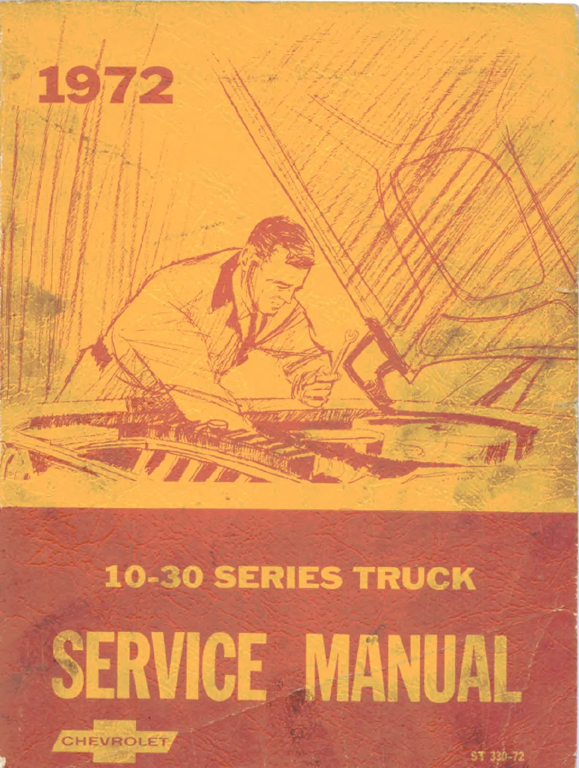
1972 Chevrolet Series 10-30 Truck Chassis Service Manual
Original price was: $34.95.$21.95Current price is: $21.95.
The factory-authorized 1972 Chevrolet Series 10-30 Truck Chassis Service Manual provides complete shop service, maintenance, and adjustment procedures for 1972 Chevy C10, C20, C30, K10, K20, Blazer, Suburban, and Step-Van models.
Description
Factory Service Information for 1972 Chevrolet Light-Duty Trucks
The 1972 Chevrolet Series 10-30 Truck Chassis Service Manual (ST 330-72) is the primary technical resource produced by the Chevrolet Motor Division of General Motors Corporation for dealership mechanics and service technicians. Designed specifically for the 1972 model year, this comprehensive workshop publication delivers factory-approved removal, installation, inspection, maintenance, and adjustment procedures covering all chassis and mechanical assemblies on Chevrolet light-duty trucks. Whether completing periodic lubrication services, rebuilding front suspension linkages, diagnosing complex climate control systems, or repairing body sheet metal, this manual provides exact engineering standards, clearance limits, and torque specifications.
File Details
- Manual Type: Factory Chassis Service Manual
- Brand: Chevrolet (General Motors Corporation)
- Model Coverage: Series 10, 20, and 30 Trucks (Conventional 2WD, 4-Wheel Drive, Forward Control, Blazer, Suburban, Step-Van)
- Publication Number: ST 330-72
- Model Year: 1972
- Language: English
- Page Count: 500 pages
- File Format: Portable Document Format (PDF)
Chapters Covered
- Section 0 — General Information and Lubrication: Model Line Up, Truck Model Designation Decoding, Vehicle Identification Number and Rating Plate, Unit and Serial Number Locations, Service Parts Identification Plate, Keys and Locks, Emergency Starting and Towing Procedures, Engine Application Chart, Load Capacity Charts, Lubrication Schedules, Fluid Viscosities, and Component Capacities
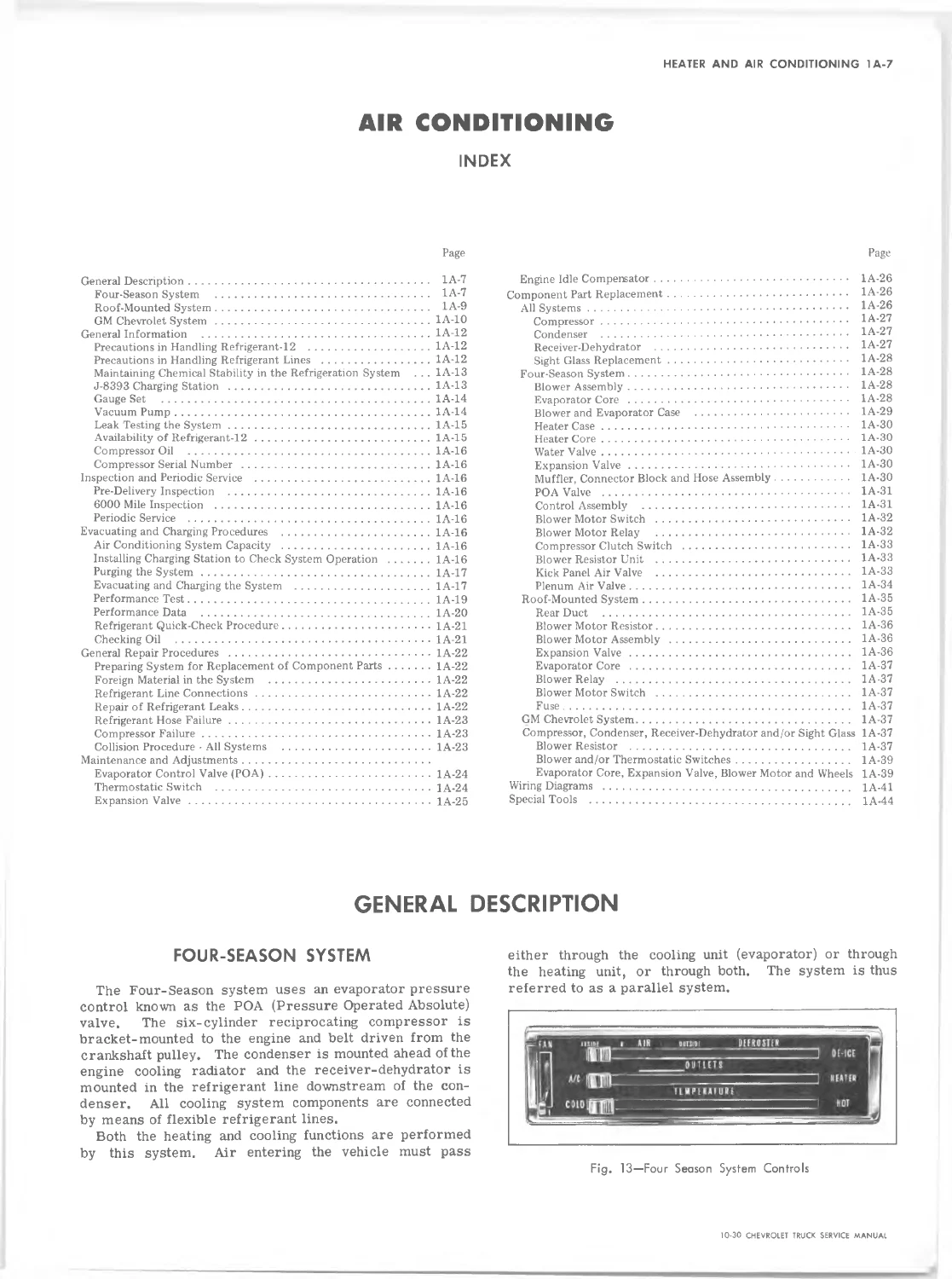
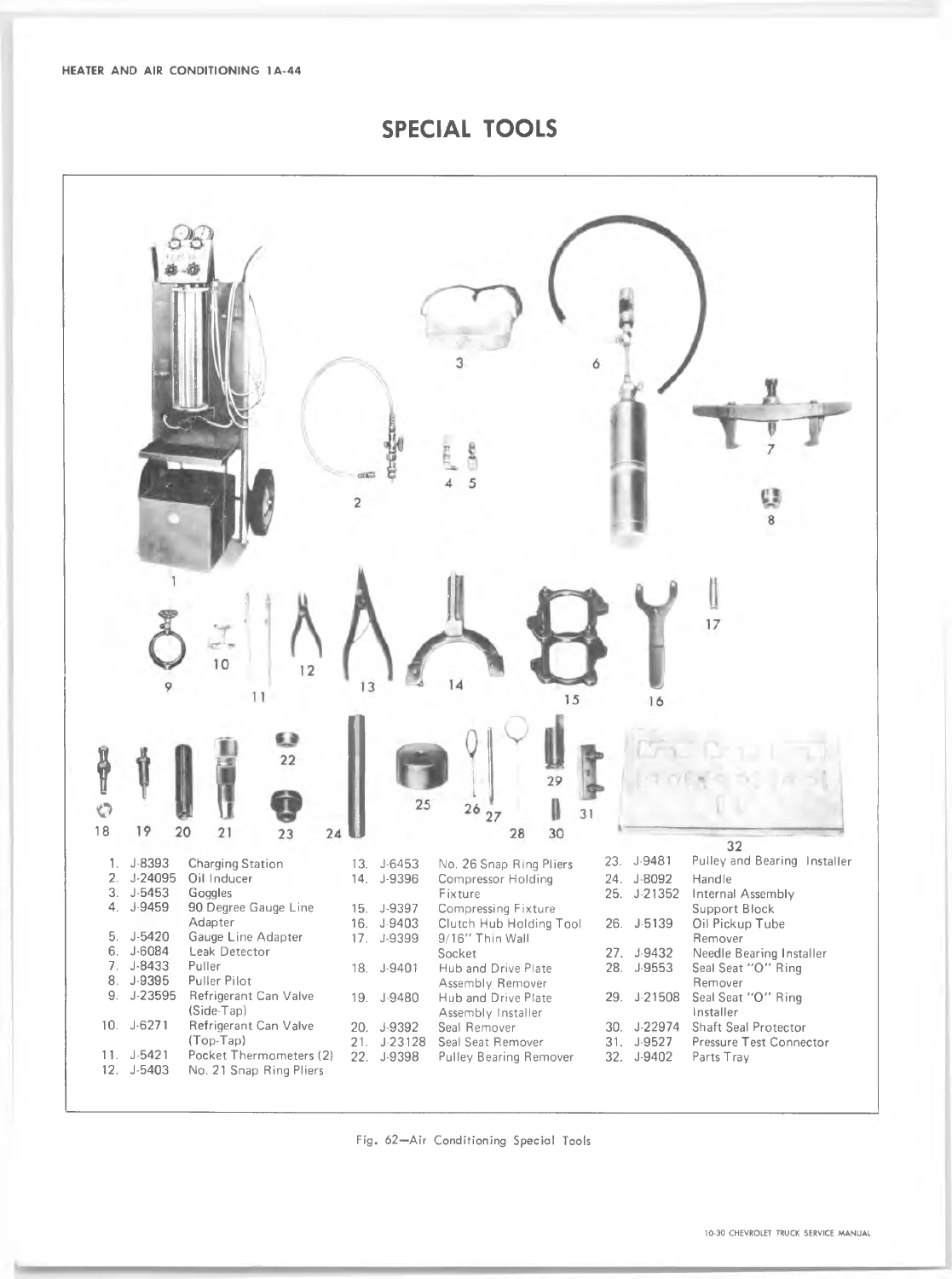
- Section 1A — Heater and Air Conditioning: Standard Dash Heater System, Suburban and Panel Dealer-Installed Auxiliary Heater, Factory Four-Season Air Conditioning System, Roof-Mounted Auxiliary Air Conditioning System, GM Chevrolet Dealer-Installed System, Evacuating and Charging Procedures, J-8393 Charging Station Operation, Compressor Service and Oil Balance, POA Valve Testing, Expansion Valve Diagnostics, Thermostatic Switches, Vacuum Controls, and System Wiring Diagrams
- Section 1B — Body: Body Mounting Hardware, Cab and Sealing Sequences, Windshield and Body Glass Installation, Reveal Molding Servicing, Cowl Ventilator Grille and Outlet Valves, Windshield Wiper Linkage and Pivot Shafts, Fleetside and Stepside Tailgate Mechanisms, Suburban Endgate and Liftgate Assemblies, Side Door Hinges and Check Assemblies, Door Windows and Ventilator Glass, Door Locks and Striker Adjustments, Interior Soft Trim Cleaning, Blazer Removable Hardtop and Fiberglass Repair, Step-Van Body and Sliding Track Doors, and Body Fastener Torque Specifications
- Section 2 — Frame: Ladder Channel Frame Construction, Crossmember Layouts, Frame Alignment and Tramming Sequences, Horizontal and Vertical Dimension Charts, Frame Straightening Guidelines, and Crack Welding and Bolting Standards
- Section 3 — Front Suspension and 4-Wheel Drive: Independent Coil Spring Front Suspension, Tapered Roller Wheel Bearing Adjustment and End-Play Checks, Alignment Procedures (Zero-Frame Caster Calculation, Camber Shim Placement, Toe-In), Shock Absorber and Stabilizer Bar Service, Coil Spring Removal with Tool J-23028, Upper and Lower Control Arm Inner Pivot Shafts and Steel Bushings, Upper and Lower Ball Joint Inspection and Replacement, Steering Knuckle Service, Front Crossmember Servicing, and 4-Wheel Drive Front Suspension Shackle Stop Clearances
- Section 4 — Rear Suspension and Driveline
- Section 5 — Brakes
- Section 6 — Engine
- Section 6K — Engine Cooling
- Section 6M — Fuel System
- Section 6T — Emission Control Systems
- Section 6Y — Engine Electrical
- Section 7 — Clutch and Transmission
- Section 8 — Fuel Tank and Exhaust System
- Section 9 — Steering
- Section 10 — Wheels and Tires
- Section 11 — Chassis Sheet Metal
- Section 12 — Electrical — Body and Chassis
- Section 13 — Radiator and Grille
- Section 14 — Bumpers
- Section 15 — Accessories
- Specifications: Detailed Vehicle Component Clearance, Torque, and Capacity Tables
This comprehensive section layout provides technicians with complete factory instructions required to troubleshoot, service, and maintain running gear, chassis sheet metal, climate controls, and driveline assemblies across the entire 1972 Chevrolet light-duty truck range.
Vehicle Identification & Model Coverage
The manual details complete model identification standards using Chevrolet’s five-digit designation system. It covers two-wheel drive conventional cabs (C10, C20, C30), four-wheel drive models (K10, K20), forward control delivery vans (P10, P20, P30), the K/5 Blazer utility, Suburban Carryalls, Step-Van 7, Steel Step-Van King, Aluminum Step-Van King, and Motor Home Chassis (PE31132 and PE31432). Complete engine availability matrices outline factory fitment for the 250 cu. in. L-6, 292 cu. in. L-6, 307 cu. in. V-8, 350 cu. in. V-8, and 402 cu. in. V-8 powerplants. In addition, technicians can locate stamped unit numbers and production prefixes for Flint and Tonawanda engines, 3-speed, 4-speed, Powerglide, Turbo Hydra-Matic 350, and Turbo Hydra-Matic 400 transmissions, Delcotron alternators, and drive axles.
Heating & Air Conditioning Engineering
Section 1A provides exhaustive guidance for servicing all factory and accessory climate control systems. It covers the baseline dash heater, the Suburban dual-core auxiliary heater, the factory parallel Four-Season air conditioning system, the Suburban roof-mounted evaporator unit, and dealer-installed GM Chevrolet systems. Step-by-step instructions guide technicians through charging station hookup, system purging into collection containers, 28–29 in. Hg deep evacuation, refrigerant metering, and propane leak detector usage. Detailed performance test tables define acceptable head pressures, POA valve suction pressures at varying altitudes, and vent discharge temperatures under calibrated ambient conditions. Critical mechanical operations include Six-Cylinder compressor replacement, compressor oil balance calculations, thermostatic switch calibration, POA valve replacement, and expansion valve bulb positioning.
Cab Sealing, Door Alignment & Fiberglass Repair
Section 1B provides extensive structural and body servicing procedures. Step-by-step windshield replacement instructions outline pinchweld flange inspection, spacer checking with packet J-22577, and cord-pulling installation techniques to guarantee weather-tight seals without glass breakage. Door alignment instructions detail three-way hinge adjustment using special wrench J-22585, inner weatherstrip cement bonding, and precise latch striker indexing to within 1/16-inch flush fitment. In addition to Fleetside, Stepside, and Suburban liftgate/endgate linkages, the manual features dedicated fiberglass body repair techniques for the K/5 Blazer hardtop. Technicians are provided with complete instructions for mixing plastic solder, feather-edging cracked resin panels, laying five-layer woven glass laminates, and fabricating structural roof braces during top removal.
Frame Alignment & Front Suspension Servicing
Sections 2 and 3 establish exact mechanical tolerances for vehicle tracking, stability, and handling. Frame alignment procedures detail tramming methods, diagonal cross-checking, and vertical datum point verification across eleven light-duty chassis wheelbases. The front suspension section outlines independent coil spring overhaul, lower control arm removal utilizing cross-shaft tool J-23028, and steel threaded pivot bushing replacement. Instructions emphasize proper tapered roller wheel bearing adjustment, requiring a looseness of .001 to .008 inch end-play and prohibiting pre-load. Front end alignment procedures include graphic calculation methods to correct caster relative to vehicle frame angles, shim placement at the upper control arm cross-shaft, and ball joint wear limits.
IMAGES PREVIEW
Professional Shop Utility & Digital Delivery
The 1972 Chevrolet Series 10-30 Truck Chassis Service Manual is an indispensable workshop tool for professional mechanics, vintage truck restorers, and private owners committed to maintaining authentic GM engineering standards. Using verified factory specifications ensures component longevity, correct fastener clamping torques, proper fluid capacities, and safe operation on both street and job site. Delivered as an instant high-resolution PDF download immediately upon checkout, this manual requires no shipping wait. It is completely portable, accessible on any computer, tablet, or smartphone, and fully printable for convenient benchtop reference in the shop.
Reviews
There are no reviews yet.