
JCB JS200 JS210 JS220 Excavator Service Manual – PDF Download
Original price was: $74.95.$49.95Current price is: $49.95.
Complete JCB JS200, JS210 and JS220 tracked excavator service manual covering engine, hydraulics, electrics, transmission, routine maintenance and more. Instant PDF download.
Description
JCB JS200, JS210, JS220 Excavator Service Manual
This comprehensive service manual covers the JCB JS200, JS210 and JS220 tracked excavators, providing complete maintenance, repair and overhaul procedures for every major system on the machine. Whether you are a professional technician, fleet maintenance manager, or owner-operator, this manual delivers the detailed technical information required to service, diagnose and repair these JCB excavators correctly.
Compiled for JCB Distributor Service Engineers who have received training from the JCB Technical Training Department, this publication assumes a sound knowledge of workshop practice, safety procedures and general techniques associated with the maintenance and repair of hydraulic earthmoving equipment. Every section is designed to guide you through the job with precision — from routine greasing schedules to complete hydraulic pump overhaul.
File Details
- Manual Type: Service Manual
- Brand: JCB
- Models Covered: JS200, JS210, JS220 (and variants)
- Engine: Isuzu 6BG1, 6-cylinder turbo charged (model BB-6BG1T)
- Language: English
- Page Count: 629
- File Format: PDF
Chapters Covered
- General Information
- Care & Safety
- Routine Maintenance
- Attachments (A)
- Body & Framework (B)
- Electrics (C)
- Hydraulics (E)
- Transmission (F)
- Track & Running Gear (J)
- Engine (K)
General Information
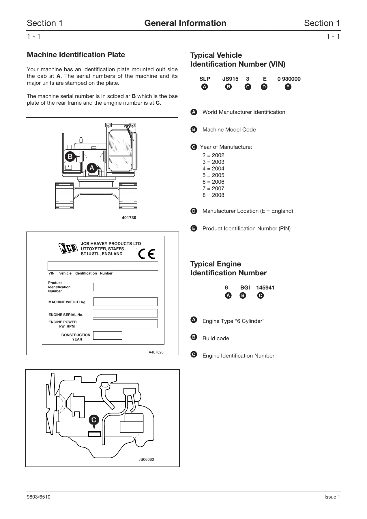
Torque settings for UNF Grade ‘S’ bolts, Metric Grade 8.8 bolts and rivet nut bolts/screws. Machine identification plate locations, Vehicle Identification Number (VIN) decoding, engine identification number format, service tool listings for body and frame, electrics, hydraulics and transmission, and sealing and retaining compounds.
Care & Safety
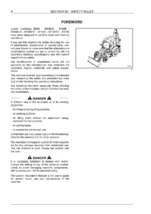
Signal word meanings (DANGER, WARNING, CAUTION), general safety warnings covering handbook requirements, decals, care and alertness, alcohol and drugs, clothing, lifting equipment, raised equipment, and operating safety including practice, machine condition, entering/leaving, controls, visibility, machine limits, exhaust gases, sparks, engine safety, passengers, safe working loads, electrical power cables, hazardous atmospheres, and maintenance safety covering modifications, welding, electrical circuits, diesel fuel, oil, hydraulic fluid, hydraulic pressure, fires, hot coolant, cleaning, soft ground, rams, hydraulic hoses, O-rings, seals, gaskets, battery, battery gases, battery terminals, petrol, arc welding, repairs, and metal splinters. Also includes safety decal locations.
Routine Maintenance
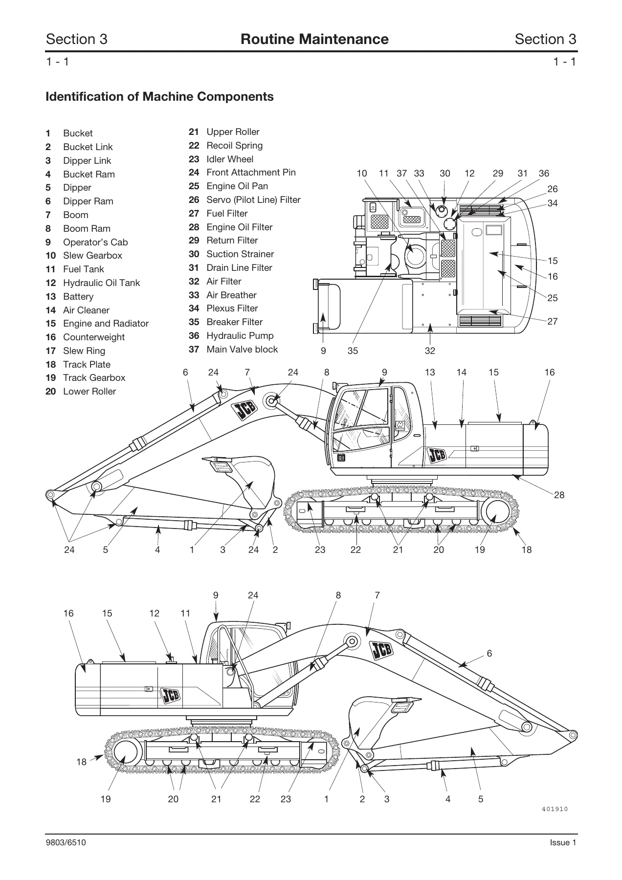
Service schedules at 10, 50, 250, 500, 1000, 2000, 4000 and 5000 operating hour intervals. Includes service capacities and lubricants, engine lubrication chart, regular maintenance and lubrication schedules, initial precautions for new machine usage, checking for damage, cleaning the machine, daily checks, greasing including slew ring bearing and slew ring teeth, fuel system including types of fuels, filling tank and checking fuel level, changing fuel filter element, draining fuel tank impurities, draining sediment bowl, bleeding the fuel system, engine oil and filter changes, checking oil level, changing air filter, adjusting/changing fan belt, checking coolant level, cleaning radiator and oil cooler, changing coolant, hydraulic system checks including checking fluid level, releasing tank pressure, topping-up fluid level, changing hydraulic fluid, draining water and sediment from hydraulic tank, cleaning/changing suction strainer, changing return filter, changing plexus filter, changing air breather element, changing servo oil filter (pilot), changing breaker in-line filter, changing drain line filter, air bleeding from hydraulic pump, rams and slew motor, battery maintenance including checking electrolyte level and battery disconnection/replacement, slew gearbox oil level and changing, track gearbox oil level and changing, checking/adjusting track tension, checking rollers and idler wheels for oil leaks, track plate inspection, cleaning tracks, checking/adjusting for side play, periodic replacement of safety related components, and obtaining replacement parts.
Attachments (A)
Boom and slew frame installation specifications, boom ram installation, dipper ram installation, dipper pivot installation, dipper and dipper ram installation, bucket ram installation, dipper and dipper link installation, bucket and bucket link installation, bucket link and bucket ram installation, bucket and dipper installation. Includes standard values, service limits, clearances and shim part numbers. Also covers static dimensions for monoboom and T.A. Boom, dig depth charts, shipping weights, weights of major components, and air conditioning including binary pressure switch settings, refrigerant and oil specifications.
Body & Framework (B)
Service tools including hand cleaner, 12V mobile oven, 240V static oven, cartridge gun, folding stand for holding glass, glass lifter, wire starter, cut-out knife, glass extractor handles, L blades, braided cutting wire, long knife, nylon spatula, rubber spacer blocks, and rivet nut tool procedure. Service procedures including direct glazing — removing broken glass and old sealant, preparing and installing new glass, cab structure checks, checking the FOPS structure, and cab panel removal.
Electrics (C)
Technical data including fuses and fuse ratings. Switches and controls including starter switch, throttle dial, SAE/ISO indicator light, hammer switch, heated seat switch, lower wiper switch, boom priority switch, radio mute switch, work light switch, auxiliary circuit switch, one touch idle switch, cigar lighter/12V powerpoint, horn switch, control lock lever, boom priority switch, courtesy light, display panel monitor, mode switch, set switch, ACK switch, scroll up/down switches, warning lamps, monitor messages, fascia panel switches including emergency stop, slew lock, overload caution, cushion, isolator, quick hitch, beacon, washer, wiper, auto idle, emergency back-up switch, mechanical engine RPM override, travel speed change button, ISO/SAE controls, servo controls immobilisation, cab interior lights, radio, heater/air conditioning controls, circuit symbols, component identification, main schematic, AMS (Advanced Management System) overview, circuit concepts including inputs (digital and analogue) and outputs (low side, high side and modulated), pulse width modulation (PWM), ECU1/EMS/FACIA power supply and network, ECU 1 supply to output drivers, engine throttle control, auto pressure boost, engine reverse rotation prevention, engine pre heat (glow plugs), engine automatic warm up, engine automatic idle, engine one touch idle, engine stop solenoid/emergency stop, limp mode system, pump control for each mode, lever lock, servo isolator, wiper and lower wiper, washer, horn, travel alarm, soft/hard (cushion), boom down delay, slew/boom priority (high dump), slew brake, slew lock (100% slew brake), 3-speed travel, work lamps, fuel level sensor/warning, engine temperature sensor/warning, coolant level warning, air filter blocked warning, hydraulic temperature sensor/warning, alternator/no charge warning, alternator charging and battery relay, quick hitch, overload caution, beacon, grab/rotate, hammer (breaker), hammer/auxiliary combined, hammer/auxiliary combined and merged, scrap magnet option, cab interior lamp, refueling pump, air conditioning, heated seat, 24 to 12 volt converter, radio and cigar lighter, service required warning, EMS set menu, EMS set + mode (5 sec) menu, EMS set + mode (20 sec) menu, fault finding including JCB Service Master diagnostic tool, HP setup overview, using HP setup, connecting the data link adaptor, starting HPSetup, data link adaptor, HP data logs, flash programming application, introduction to the diagnostics tool, connecting to the vehicle, starting diagnostic mode, circuit diagrams, indicator lights (LEDs), stopping diagnostic mode, language setting, list of text messages displayed on the EMS, fault finding without using the JCB Service Master diagnostic tool, service procedures including electrical testing methods, using a multimeter, testing of ECU (Electronic Control Unit), wiring harness repair procedure, battery, harness data including harness location and interconnection, main harness connector location, main harness key to connectors, main harness drawings, main harness data, facia link harness connector location, facia link harness key to connectors, facia link harness drawings, facia link harness data, cab harness connector location, cab harness key to connectors, cab harness drawings, and cab harness data.
Hydraulics (E)
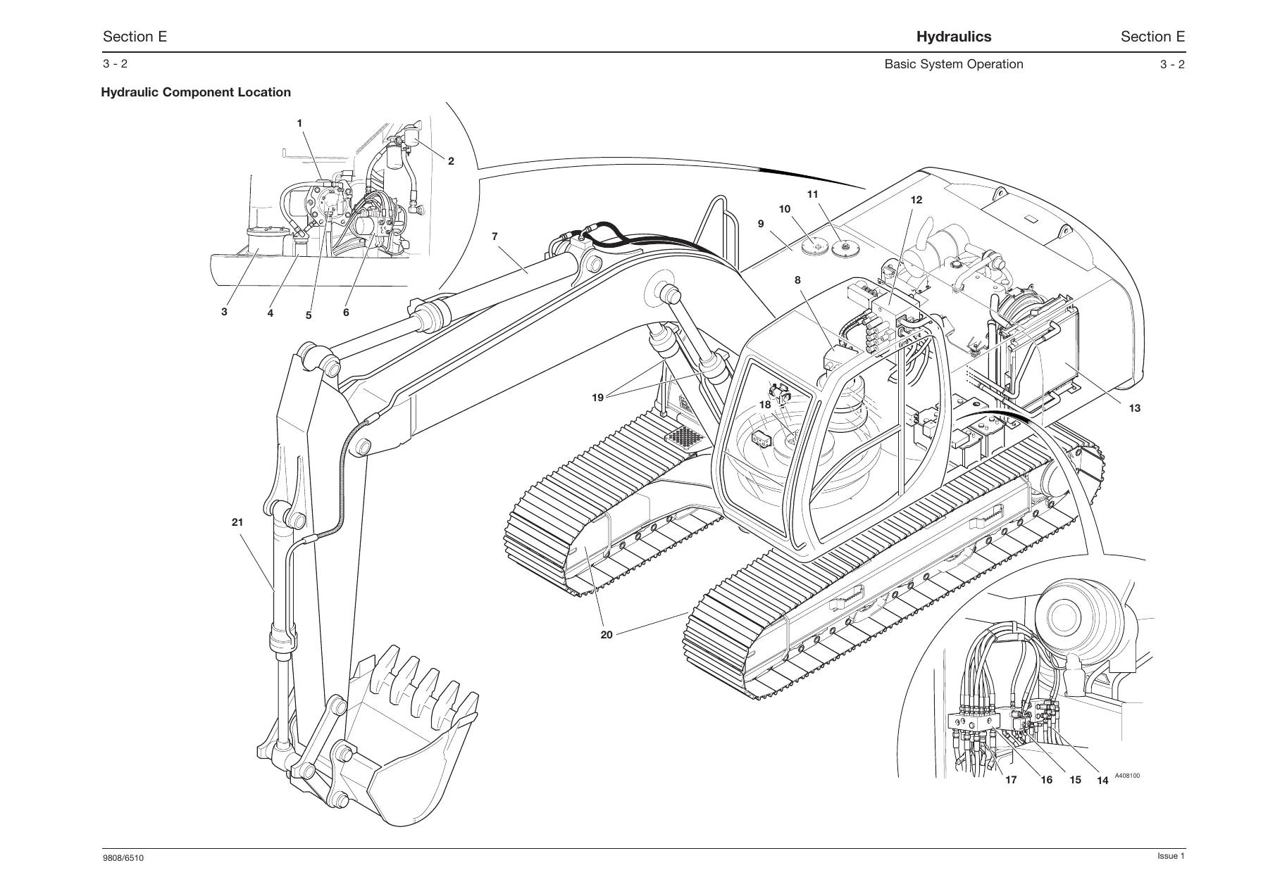
Service tools including pressure test ‘T’ adapters, pressure test adapters, hydraulic pressure test gauges and connections, hand pump equipment, female cone blanking plug, male cone blanking plug, socket box wrench, nut adapter, seal ring tool, stopper, bearing rig, ram dismantling and assembly tools including ram piston head nut, spanner requirements, jig for inserting and correcting seal ring, jig for pulling out and press-fitting bushing, jig for press-fitting wiper ring, and jig for inserting cylinder head. Technical data including hydraulic pump specifications, hydraulic pump regulator, proportional pressure reducing valve, main control valve, boom ram, dipper ram, bucket ram, slew equipment, and slew motor. Basic system operation including hydraulic component location, introduction to hydraulic schematic symbols, circuit descriptions including component identification, main hydraulic schematic, servo line, servo pressure and return line, main control valve, hydraulic pump operation, hydraulic pump regulation, neutral circuit, straight line travel, travel — middle speed, boom up, boom down, dipper out, dipper in, bucket opening, bucket closing, priority valves, slew motor configuration, slew motor reduction gear, slew circuit, slew brake, auxiliary/merged flow, hammer, remote control valve (services), cushion valve, solenoid valve (8 spool), shuttle valve, and rotary coupling. Fault finding for main control valve, relief valve, hydraulic system, slew motor, hydraulic pump, and hydraulic rams. Fault finding tests. Service procedures including hydraulic contamination, test 001 negative control signal, test 002 max flow signal, test 003 main pump pressure, test 004 horse power control, test 005 operation of main hydraulic spool, test 006 pressure switches, test 007 engine speed setting, test 008 machine cycle times, test 010 hose burst check valve, test 011 slew brake pressure, test 012 track motor relief valve setting, test 013 track motor drain line flow rate, test 014 loss of high speed tracking, test 015 machine selects high gear, test 016 flow testing pumps, test 017 testing slew bearing, ram creep tests — all services, pressure testing general, pressure testing points, pressure relief valve location, main relief valve pressure, servo relief pressure, slew motor pressure relief, auxiliary relief valves, travel motor relief pressure. Removal and replacement for hydraulic pump, remote control valve (hand control), direction control valve, solenoid valve (8 spool), shuttle valve, cushion valve, slew brake valve, slew motor, rotary coupling, and hydraulic rams including bucket ram, dipper ram, boom ram, dismantling and assembly, piston ram nut removal and replacement, and hydraulic rams reconditioning.
Transmission (F)
Service tools including track gearbox jig, re-sealing tool, stopper for assembly of hydraulic motor on track gearbox, ring nut tool, and planet gear tool. Technical data for travel equipment including type, motor displacement, working pressure, working flow, reduction gears, deceleration ratio, parking brake, brake torque, brake pressure release, brake valve pressure relief, and dry weight. Basic system operation including travel motor operation at middle speed, slow speed travel (creep), and high speed. Fault finding for track motor, track gearbox, and related components. Track motor removal and replacement, and dismantling and assembly including track gearbox and track motor.
Track & Running Gear (J)
Torque specifications for drive sprocket fastening bolts, idler wheel installation bolts, top roller installation bolts, bottom roller installation bolts, recoil unit installation bolts, and track shoe bolts. Idler wheel and recoil unit removal and replacement. Idler wheel dismantling and assembly, wear limits. Grease cylinder removal and replacement, dismantling and assembly. Drive sprocket removal and replacement, wear limits. Top roller removal and replacement, dismantling and assembly, wear limits. Bottom roller removal and replacement, dismantling and assembly, wear limits.
Engine (K)
Technical data for the Isuzu 6BG1, 6-cylinder turbo charged engine (model BB-6BG1T) including type, bore, stroke, swept volume, compression ratio, compression pressure, firing order, valve clearance (cold) for inlet and exhaust, dry weight, fuel system maximum speed (no load), injection timing (static), injector opening pressure, and induction system air cleaner type.
What This JCB Service Manual Enables You to Do
This JCB JS200, JS210, JS220 service manual gives you the complete technical authority to maintain, diagnose and repair these tracked excavators to professional standards. From routine 10-hour greasing and daily checks through to major component overhaul, every procedure is laid out with the specifications, torque values, service limits and clearances you need to get the job done correctly the first time.
When a hydraulic fault brings a machine to a standstill, you have the full circuit descriptions, pressure testing procedures and fault finding charts to trace the problem systematically — whether it is a pump regulation issue, a sticking spool, a failed relief valve or internal ram leakage. The electrical section covers the entire AMS (Advanced Management System) including the CAN-BUS network, ECU inputs and outputs, throttle control, pump control and every monitored function, with harness data and connector pin information so you can test circuits accurately rather than guessing.
For engine work, the manual provides the Isuzu 6BG1 technical data you need, while the transmission and track sections give you the procedures to remove, dismantle, inspect and reassemble track motors, gearboxes, idler wheels, rollers and sprockets with confidence. The attachments section includes pin and bushing wear limits, shim part numbers and clearance specifications for every pivot point on the boom, dipper and bucket linkage, so you can restore precise, safe operation.
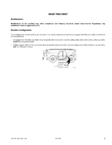
This is not a generic overview or a collection of scanned fragments. It is a complete service manual with over 600 pages of JCB-specific procedures, illustrations, exploded views, hydraulic schematics, wiring diagrams and specification tables — the same technical information used by JCB Distributor Service Engineers.
IMAGES PREVIEW
Delivered as an instant PDF download, this manual is available immediately after payment. There is no shipping, no waiting and no physical book to keep track of. The PDF can be viewed on any device — laptop, tablet or smartphone — and individual pages or sections can be printed for use in the workshop. Keep it on your computer, your service truck tablet or your phone; the information is always at hand when you need it. Whether you are servicing one machine or managing a fleet of JS200, JS210 and JS220 excavators, this manual is an essential tool for every job.
Reviews
There are no reviews yet.