
JCB VMT380 & VMT430 Tandem Roller Service Manual – Full Workshop Repair PDF
Original price was: $51.95.$39.95Current price is: $39.95.
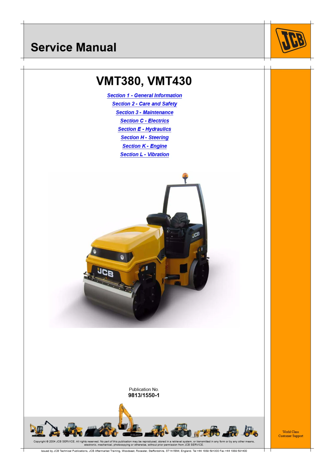
Complete JCB service manual for VMT380 and VMT430 tandem vibratory rollers from serial 2803540 onwards. Covers engine, hydraulics, electrics, steering, vibration, maintenance schedules and torque settings. Instant PDF download.
Description
JCB VMT380 & VMT430 Tandem Roller Service Manual
This JCB VMT380 & VMT430 Tandem Roller Service Manual is the complete workshop reference for maintaining, diagnosing and repairing these compact tandem vibratory rollers. Covering machines from serial number 2803540 onwards, it was prepared for JCB distributor service engineers and technical personnel who need accurate procedures, correct torque figures and system-level understanding. Every section is written to be used at the bench and in the field — whether you are adjusting the drive belt, bleeding the fuel system, testing the alternator, or interpreting a hydraulic schematic to trace a fault.
The manual applies to both the VMT380 and VMT430 models. Because the two machines share the same serial number break and much of the same architecture, one manual covers both, making it a practical single reference for mixed fleets. The engine is a Kohler unit, and the hydraulic system uses a Rexroth-Bosch combination pump, Poclain drum drive motors and Turolla vibration and steering components.
File Details
- Manual type: Service Manual
- Brand: JCB (Vibromax)
- Models covered: VMT380, VMT430
- Serial number applicability: From 2803540 onwards (both models)
- Language: English
- Page count: Approximately 300 pages
- File format: PDF
- Publication number: 9813/1550
Chapters Covered
The manual is organised into numbered and alphabetically coded sections. The top-level contents are:
- Section 1 — General Information
- Section 2 — Care and Safety
- Section 3 — Maintenance
- Section C — Electrics
- Section E — Hydraulics
- Section H — Steering
- Section K — Engine
- Section L — Vibration
Section 1 — General Information
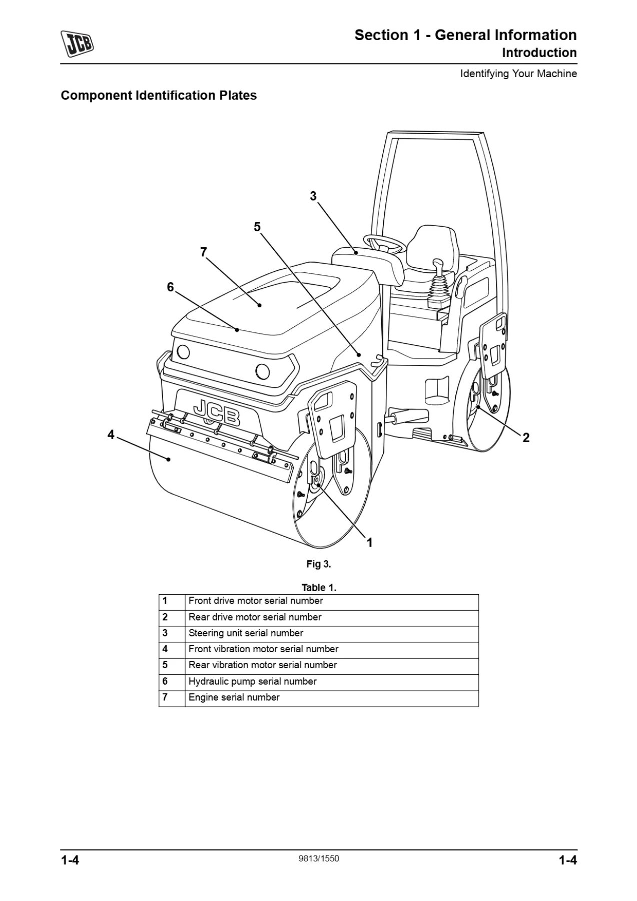
Opens with identification details: machine model and serial number locations, the product identification plate layout, engine identification, ROPS and FOPS data plates, and component identification plates. The torque settings chapter is extensive, covering zinc plated and Dacromet fasteners, UNF Grade ‘S’ fasteners, metric Grade 8.8, 10.9 and 12.9 fasteners, rivet nut bolts, internal hexagon cap screws, Vibromax-specific torque figures, and hydraulic connection torque tables for BSP adaptors, SAE connections, bonded washers and ‘Torque Stop’ hose systems. Service tools are listed numerically with detail references for body/framework, electrics and hydraulics, including the slide hammer kit, rivet nut tool, Fluke meter, hydraulic temperature probe, digital tachometer and the hydraulic circuit pressure test kit. Sealing and retaining compounds and hydraulic schematic colour codes are also defined.
Section 2 — Care and Safety
Contains the safety notices, signal word definitions (DANGER, WARNING, CAUTION), and a detailed safety check list covering general safety, operating safety and maintenance safety. Topics include clothing, alcohol and drugs, mobile phones, lifting equipment, raised equipment and machines, lightning, machine modifications, work sites, communications, parking, banks and trenches, sparks and explosions, hazardous atmospheres, visibility, electrical power cables, working platforms, ROPS/FOPS damage, travelling at speed, controls, passengers, fires, roll-over procedures, entering and leaving, hillsides, fluid under pressure, hydraulic pressure, fuel, oil, soft ground, rams, cleaning, ‘O’ rings and seals, hydraulic hoses, Waxoyl, working under the machine, fluoroelastomeric seals, arc welding, counterweights, compressed air, petrol, cooling system pressure, batteries, battery terminals and engine turning. Safety label identification with part numbers and descriptions is also included.
Section 3 — Maintenance
The routine maintenance section covers owner/operator support, service/maintenance agreements, initial service and inspection, obtaining replacement parts, health and safety, lubricants, battery safety, and full service schedules. The schedules define pre-start cold checks, service points and fluid levels, functional tests and final inspection at 10, 50, first 100, 500, 1000 and 2000 hour intervals, with calendar equivalents. Fluid, lubricant and capacity tables give fuel tank, engine oil, coolant, hydraulic tank and vibration system capacities with recommended specifications. The section also covers preparing the machine for maintenance, cleaning procedures, access panels, brakes, electrical system (battery, jump starting, fuses and relays), engine (oil and filter, cooling system, drive belt, air filter), fuel system (tank filling and draining, filter elements, water separator, bleeding), hydraulic system (oil and filter, pressure release), sprinkler system, drum scrapers and rubber buffers, and vibration system grease requirements.
Section C — Electrics
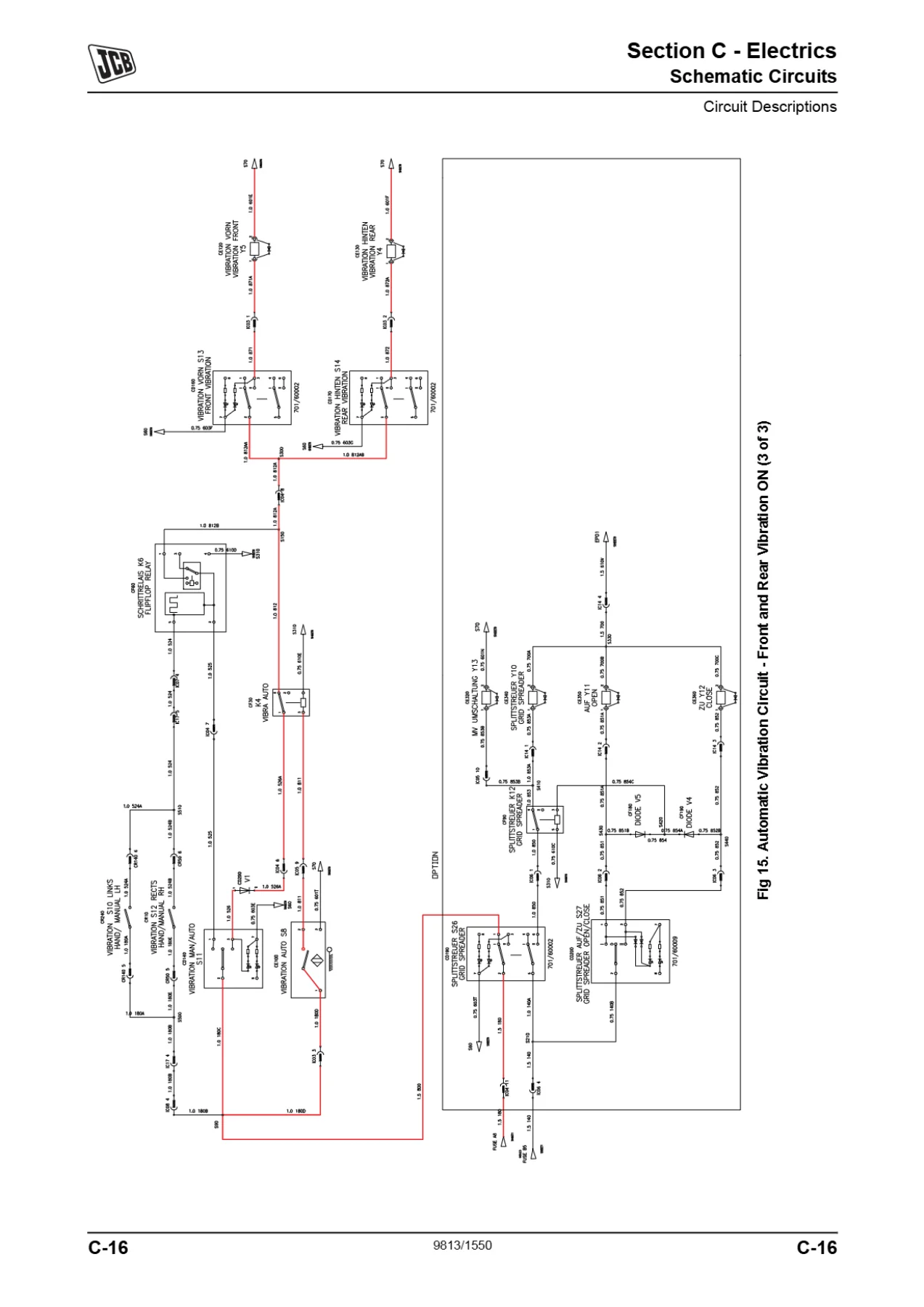
Provides fuse and relay data, Vibromax relay explanation, full electrical schematic circuits, and circuit descriptions for vibration, engine start, park brake and sprinklers. Harness data drawings and interconnections are included for lights, seat, engine, fuse and relay, dashboard, front and rear harnesses. Service procedures cover using a multimeter (DC voltage, resistance, continuity, frequency, diode testing), battery maintenance and testing, specific gravity testing, alternator general description and charging tests, starter motor starting circuit tests, and wiring harness repair using crimp splices and a butane heater.
Section E — Hydraulics
Covers technical data for hydraulic pumps, propulsion pump, propulsion motors, vibration/charge pump, vibration motors, steering pump, steering control unit and hydraulic pressures. Basic operation explains hydraulic schematic symbols including general symbols, rams, pumps and motors, control valves, energy transmissions and conditioning, and control mechanisms, with an example schematic circuit. Full hydraulic circuit diagrams and circuit descriptions cover pressure measurement points, charge circuit, brake release circuit, steering circuit, drive circuit, flushing circuit, and vibration circuits (front and rear, rear only, front only). Service procedures address hydraulic contamination, fluid quality, cleaning, filters, positional type adaptors, venting pressure, connecting and disconnecting hoses, hydraulic pump, vibration control block, fault finding tables for drive and steering systems, hydraulic hose and pipework, and hydraulic rams.
Section H — Steering
The steering section covers the steering circuit and its integration with the hydraulic system. The steering pump is a Turolla SNP2NN/8 unit and the steering orbitrol is a Rexroth-Bosch LAGC 200 with 200 cm displacement. Steering pressure is measured at MP6, with a maximum of 165 bar (180 bar in the technical data table). The steering circuit description is included in Section E’s circuit descriptions.
Section K — Engine
The engine section covers the Kohler engine fitted to these machines. Maintenance procedures include checking oil level, changing oil and filter, checking coolant level, changing coolant, adjusting the drive belt, cleaning the air filter dust valve, and changing air filter elements. The fuel system chapter covers low fuel levels, filling the tank, draining the tank, changing the engine fuel filter element, draining the water separator pre-filter, changing the water separator pre-filter, and bleeding the system. Engine specifications include oil capacity of 8.5 litres, coolant capacity of 7 litres, and fuel tank capacity of 100 litres.
Section L — Vibration
Covers the vibration system, including grease-lubricated shaft machines. The vibration motors are Turolla SNM2NL/011B402AA units with 10.8 ccm/rev displacement, maximum speed of 4000 rpm and maximum working pressure of 250 bar. The vibration control block is a Bucher Hydraulics STB VIBRA 2F BRAKE unit with pressure valve setting of 130.8 +/- 5 bar and stop valve setting of 31 +/- 5 bar, with a flow of 45 L/min. The vibration circuit descriptions cover front and rear vibration, rear only, and front only configurations. Vibration pressure is measured at MP4 (250 bar in maintenance data, 280 bar in the hydraulic technical data).
Technical Specifications Included
- Combination pump: Rexroth-Bosch A4VG28 – AZPF16, operating speed 2700 RPM, drive displacement 28 ccm/rev, vibration displacement 16 ccm/rev
- Drum drive motor: Poclain MK05-2-124-F04-1340-0000, 670 cm displacement, maximum 55 rpm, 400 bar working pressure
- Vibration motor: Turolla SNM2NL/011B402AA, 10.8 ccm/rev, maximum 4000 rpm, 250 bar working pressure
- Steer pump: Turolla SNP2NN/8
- Steer orbitrol: Rexroth-Bosch 200 N12/200, LAGC 200, 200 cm displacement
- Vibration control block: Bucher Hydraulics STB VIBRA 2F BRAKE
- Charge pressure filter: Hydac Druckfilter LPF 55 – IP69
- Hydraulic pressures: Drive backwards 425 bar, drive forwards 425 bar, charge 25 bar, vibration 250 bar, steering 165 bar, edge cutter 160 bar
Who This Manual Is For
This JCB VMT380 VMT430 service manual is intended for JCB distributor service engineers, trained technicians, fleet maintenance managers and serious owner-operators who need to perform repairs and diagnostics to manufacturer standard. It assumes a sound knowledge of workshop practice, safety procedures and general techniques associated with hydraulic earthmoving equipment. The procedures, torque settings and specifications are presented in a format that supports systematic fault finding and correct reassembly.
Because the manual covers both the VMT380 and VMT430 from serial 2803540 onwards, it is suitable for machines in that serial range regardless of whether they are used in highway maintenance, landscaping, construction site services or general compaction work. The safety information is repeated throughout the manual, so it remains visible at the point of use rather than being confined to a single section.
Why This Manual Matters
Correct torque values prevent fastener failure and component damage. Accurate hydraulic pressures and flow rates keep the drive, vibration and steering systems operating within design limits. Proper bleeding procedures prevent fuel injection pump damage and rough running. Understanding the electrical schematics and relay logic allows faults to be traced efficiently rather than by parts replacement. This manual provides all of that in one place, with the specific values and procedures that apply to these machines.
Whether you are performing a routine 500-hour service, diagnosing a vibration fault, repairing a drum drive motor, or rebuilding a hydraulic pump, the JCB VMT380 VMT430 service manual gives you the reference material to do the job correctly. It is not a generic guide — it is the document produced for these specific tandem rollers.
IMAGES PREVIEW
Instant PDF Delivery
This JCB VMT380 VMT430 tandem roller service manual is available as an instant PDF download. No shipping, no waiting for a physical book. Once payment is complete, you can access the file immediately and view it on any device — laptop, tablet or smartphone. The PDF is printable, so you can produce workshop copies of the sections you need, or keep the entire manual on a tablet for easy reference in the field. Whether you are working in the workshop or at a remote site, the manual is available when you need it.

Reviews
There are no reviews yet.