
★ TRUSTED BY 321,897+ PROFESSIONALS WORLDWIDE
🏢
Trusted Business
Verified & Licensed
🛡️
Virus Free Files
100% Safe Downloads
🔒
Secure Payment
SSL Protected
Instant Delivery
Available Immediately
Sale!

JLG 400S & 460SJ Illustrated Parts Manual 3120789 Rev AG – PDF Download

Original price was: $39.95.Current price is: $24.95.

Complete JLG 400S and 460SJ illustrated parts manual, document 3120789 Rev AG. Exploded views, part numbers and serial number breaks for frame, turntable, boom, platform, cylinder, hydraulic and electrical systems across Caterpillar, Deutz, Ford, GM and Isuzu powered machines.

Instant PDF Download
Available immediately
💾
Save to Your Device
Download & keep forever
🛡️
Antivirus Scanned
100% virus-free
🌍
Trusted Worldwide
175,000+ customers

Description

JLG 400S & 460SJ Illustrated Parts Manual – Document 3120789 Rev AG

This is the complete illustrated parts manual for the JLG 400S and 460SJ lift machines, published under document number 3120789, Revision AG. It is the parts identification reference used for ordering and verifying components across both models, from the axle and steering installation through the platform and console assemblies. Every major figure includes an exploded illustration matched to a parts list with item numbers, part numbers, quantities, descriptions and revision levels, plus the serial number breaks that tell you which version of a component belongs on a specific machine.

File Details

  • Manual type: Illustrated Parts Manual
  • Brand: JLG
  • Models covered: 400S, 460SJ
  • Document number: 3120789
  • Revision: Rev AG (revision log runs from the original issue through the AG revision)
  • Language: English
  • Page count: 392 pages
  • File format: PDF

Chapters Covered

  • Section 1 – Frame: axle and steering installations (2WD, 2WD with tow package, 4WD), tire and wheel drive installations, drive hub assemblies, drive hub/brake assemblies, drive motor assemblies (4-bolt original equipment and 5-bolt field service replacement), frame valves and shields, semi-track installation, tow package installation
  • Section 2 – Turntable: valves and tilt indicator, main control valve assembly, articulating jib valve assembly, turntable and swing drive installations, swing brake, swing hub, swing motor, Caterpillar / Deutz / Ford / GM / Isuzu engine installations, piston pump, gear pump, auxiliary pump, tank installations, ground control box (with and without ADE system), electrical options, hoods, 2500W and 7500W SkyPower generator installations, SkyAir compressor
  • Section 3 – Boom: boom installations, boom assembly (400S), boom assembly (460SJ), rotator assemblies, platform support installation with LSS and without SkyGlazier
  • Section 4 – Platform: platform installation (front entry and side entry), Soft Touch installation, platform console assembly (without and with ADE system), controller assemblies (swing/lift and drive/steer, both ADE and non-ADE), SkyGlazier, SkyCutter, plasma cutter assembly, SkyWelder / SkyCutter combo, SkyWelder installations, welder assembly, pipe racks installation
  • Section 5 – Cylinder: axle lockout cylinder, level (platform slave) cylinder, lift cylinder (jib and main), master cylinder, steer cylinder, telescope cylinder
  • Section 6 – Hydraulic: axle lockout hydraulic diagram, drive hydraulic diagram (2WD and 4WD), standard hydraulic diagram, hydraulic diagram list
  • Section 7 – Electrical: electrical diagram list, harness components installation (without ADE system), harness components installation (with ADE system)
  • Section 8 – Decals: decal installation (ANSI spec), decal installation (country spec)
  • Section 9 – Recommended Service Parts Stock: standard parts, variable parts
  • Section 10 – Special Options: special options list
  • Part Number Index

Complete PDF Bookmark Tree

Complete Bookmarks

The complete bookmarks in the “JLG 400S & 460SJ Illustrated Parts Manual 3120789 Rev AG – PDF Download” are as follows:

SECTION 1 – FRAMEp. 11
FIGURE 1-1. AXLE AND STEERING INSTALLATION – 2WD WITHOUT TOW PACKAGEp. 12
FIGURE 1-2. AXLE AND STEERING INSTALLATION – 2WD WITH TOW PACKAGEp. 16
FIGURE 1-3. AXLE AND STEERING INSTALLATION – 4WDp. 20
FIGURE 1-4. TIRE AND WHEEL DRIVE INSTALLATIONSp. 26
FIGURE 1-5. DRIVE HUB ASSEMBLY (4WD FRONT) (Prior to SN 0300076633)p. 30
FIGURE 1-6. DRIVE HUB/BRAKE ASSEMBLY (REAR) (Prior to SN 0300076633)p. 32
FIGURE 1-7. DRIVE HUB AND HUB WITH BRAKE ASSEMBLIES (SN 0300076633 through 0300096000)p. 36
FIGURE 1-8. DRIVE MOTOR ASSEMBLY (ORIGINAL EQUIPMENT – 4 BOLT ASSEMBLY)p. 40
FIGURE 1-9. DRIVE MOTOR ASSEMBLY (FIELD SERVICE REPLACEMENT – 5 BOLT ASSEMBLY)p. 44
FIGURE 1-10. FRAME VALVES AND SHIELDS INSTALLATIONp. 48
FIGURE 1-11. SEMI-TRACK INSTALLATIONp. 52
FIGURE 1-12. TOW PACKAGE INSTALLATIONp. 56
SECTION 2 – TURNTABLEp. 59
FIGURE 2-1. VALVES AND TILT INDICATOR INSTALLATIONSp. 60
FIGURE 2-2. MAIN CONTROL VALVE ASSEMBLYp. 64
FIGURE 2-3. ARTICULATING JIB VALVE ASSEMBLYp. 68
FIGURE 2-4. TURNTABLE AND SWING DRIVE INSTALLATIONSp. 70
FIGURE 2-5. SWING BRAKE ASSEMBLYp. 74
FIGURE 2-6. SWING HUB ASSEMBLYp. 76
FIGURE 2-7. SWING MOTOR ASSEMBLYp. 78
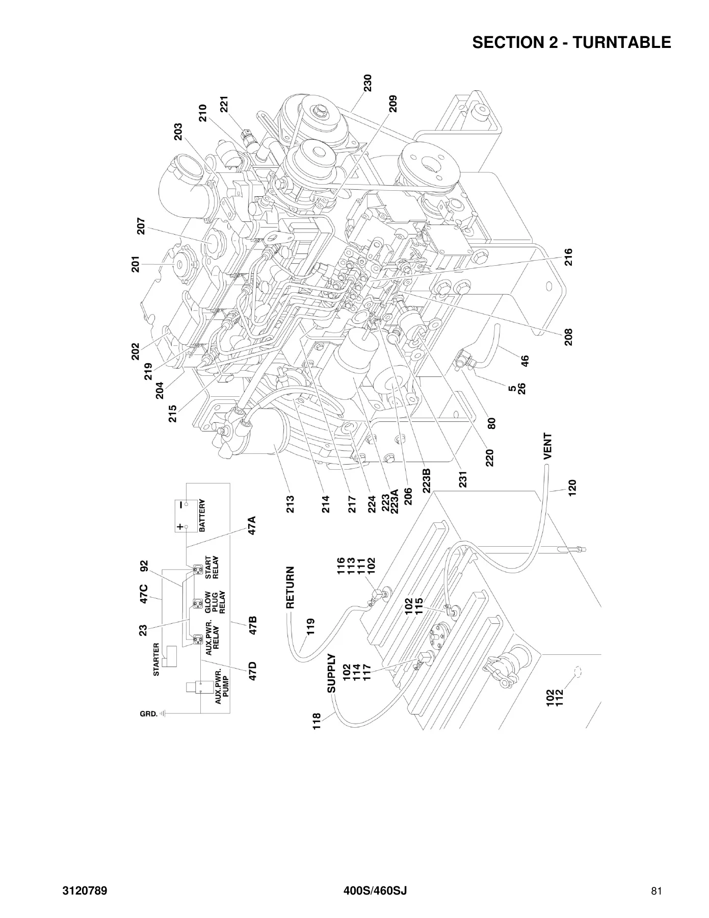
FIGURE 2-8. CATERPILLAR ENGINE INSTALLATIONp. 80
FIGURE 2-9. DEUTZ ENGINE INSTALLATION (Prior to SN 0300077682)p. 88
FIGURE 2-10. DEUTZ ENGINE INSTALLATION (SN 0300077682 through 0300096000)p. 94
FIGURE 2-11. FORD ENGINE INSTALLATION (Prior to SN 0300078473)p. 102
FIGURE 2-12. FORD ENGINE INSTALLATION (SN 0300078473 through 0300096000)p. 110
FIGURE 2-13. DUAL FUEL INSTALLATIONS (GAS MACHINES ONLY)p. 118
FIGURE 2-14. GM ENGINE INSTALLATIONp. 122
FIGURE 2-15. ISUZU ENGINE INSTALLATION – 4LE1p. 128
FIGURE 2-16. PISTON PUMP ASSEMBLYp. 132
FIGURE 2-17. GEAR PUMP ASSEMBLYp. 136
FIGURE 2-18. AUXILIARY PUMP ASSEMBLYp. 138
FIGURE 2-19. TANK INSTALLATIONSp. 142
FIGURE 2-20. GROUND CONTROL BOX ASSEMBLY WITHOUT ADE SYSTEMp. 146
FIGURE 2-21. GROUND CONTROL BOX ASSEMBLY WITH ADE SYSTEMp. 150
FIGURE 2-22. ELECTRICAL OPTIONS INSTALLATION (TURNTABLE MOUNTED)p. 156
FIGURE 2-23. HOODS INSTALLATIONp. 160
FIGURE 2-24. 2500W GENERATOR INSTALLATION – CATERPILLAR MACHINES (OPTIONAL)p. 164
FIGURE 2-25. 2500W GENERATOR INSTALLATION – DEUTZ MACHINES (OPTIONAL)p. 168
FIGURE 2-26. 2500W GENERATOR INSTALLATION – FORD MACHINES (OPTIONAL) (Prior to SN 0300078473)p. 172
FIGURE 2-27. 2500W GENERATOR INSTALLATION – FORD MACHINES (OPTIONAL) (SN 0300078473 through 0300096000)p. 176
FIGURE 2-28. 2500W GENERATOR INSTALLATION – GM MACHINES (OPTIONAL)p. 180
FIGURE 2-29. 2500W GENERATOR INSTALLATION – ISUZU MACHINES (OPTIONAL)p. 184
FIGURE 2-30. 7500W SKYPOWER GENERATOR INSTALLATION – CATERPILLAR AND DEUTZ ENGINESp. 188
FIGURE 2-31. 7500W SKYPOWER GENERATOR INSTALLATION – FORD ENGINESp. 194
FIGURE 2-32. 7500W SKYPOWER GENERATOR INSTALLATION – GM ENGINESp. 198
FIGURE 2-33. SKYAIR COMPRESSOR INSTALLATIONp. 204
FIGURE 2-34. SKYAIR COMPRESSOR PARTSp. 206
SECTION 3 – BOOMp. 209
FIGURE 3-1. BOOM INSTALLATIONSp. 210
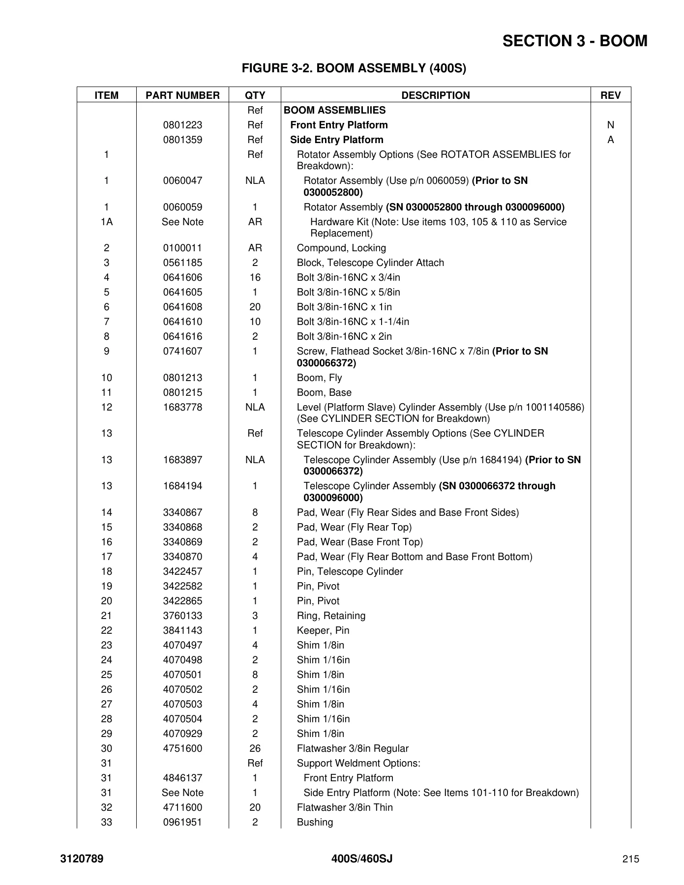
FIGURE 3-2. BOOM ASSEMBLY (400S)p. 214
FIGURE 3-3. BOOM ASSEMBLY (460SJ)p. 218
FIGURE 3-4. ROTATOR ASSEMBLIESp. 222
FIGURE 3-5. PLATFORM SUPPORT INSTALLATION – WITH LSS & WITHOUT SKYGLAZIERp. 226
SECTION 4 – PLATFORMp. 229
FIGURE 4-1. PLATFORM INSTALLATION (FRONT ENTRY PLATFORM)p. 230
FIGURE 4-2. PLATFORM INSTALLATION (SIDE ENTRY PLATFORM)p. 234
FIGURE 4-3. SOFT TOUCH INSTALLATION (FRONT ENTRY PLATFORM) (OPTIONAL)p. 238
FIGURE 4-4. SOFT TOUCH INSTALLATION (SIDE ENTRY PLATFORM) (OPTIONAL)p. 240
FIGURE 4-5. PLATFORM CONSOLE ASSEMBLY WITHOUT ADE SYSTEMp. 242
FIGURE 4-6. PLATFORM CONSOLE ASSEMBLY WITH ADE SYSTEMp. 246
FIGURE 4-7. CONTROLLER ASSEMBLY (SWING AND LIFT) (WITHOUT ADE SYSTEM)p. 250
FIGURE 4-8. CONTROLLER ASSEMBLY (LIFT AND SWING) (WITH ADE SYSTEM)p. 252
FIGURE 4-9. CONTROLLER ASSEMBLY (LIFT AND SWING) (WITH ADE SYSTEM)p. 254
FIGURE 4-10. CONTROLLER ASSEMBLY (LIFT AND SWING) (WITH ADE SYSTEM)p. 256
FIGURE 4-11. CONTROLLER ASSEMBLY (DRIVE AND STEER) (WITHOUT ADE SYSTEM)p. 260
FIGURE 4-12. CONTROLLER ASSEMBLY (DRIVE AND STEER) (WITH ADE SYSTEM)p. 262
FIGURE 4-13. CONTROLLER ASSEMBLY (DRIVE AND STEER) (WITH ADE SYSTEM)p. 264
FIGURE 4-14. CONTROLLER ASSEMBLY (DRIVE AND STEER) (WITH ADE SYSTEM)p. 266
FIGURE 4-15. SKYGLAZIER INSTALLATIONp. 268
FIGURE 4-16. SKYCUTTER INSTALLATIONp. 270
FIGURE 4-17. PLASMA CUTTER ASSEMBLYp. 272
FIGURE 4-18. SKYWELDER/SKYCUTTER COMBO INSTALLATION (60HZ)p. 274
FIGURE 4-19. SKYWELDER INSTALLATION (Prior to SN 0300068333)p. 278
FIGURE 4-20. SKYWELDER INSTALLATION (50HZ) (SN 0300068333 through 0300096000)p. 284
FIGURE 4-21. SKYWELDER INSTALLATION (60HZ) (SN 0300068333 through 0300096000)p. 286
FIGURE 4-22. WELDER ASSEMBLYp. 288
FIGURE 4-23. PIPE RACKS INSTALLATIONp. 290
SECTION 5 – CYLINDERp. 293
FIGURE 5-1. AXLE LOCKOUT CYLINDER ASSEMBLYp. 294
FIGURE 5-2. LEVEL (PLATFORM SLAVE) CYLINDER ASSEMBLYp. 296
FIGURE 5-3. LEVEL (PLATFORM SLAVE) CYLINDER ASSEMBLY (SERVICE REPLACEMENT CYLINDER) (400S)p. 298
FIGURE 5-4. LIFT CYLINDER ASSEMBLY – JIB (ORIGINAL EQUIPMENT) (460SJ)p. 300
FIGURE 5-5. LIFT CYLINDER ASSEMBLY – JIB (USAGE MAY VARY) (SERVICE REPLACEMENT) (460SJ)p. 302
FIGURE 5-6. LIFT CYLINDER ASSEMBLY – JIB (USAGE MAY VARY) (SERVICE REPLACEMENT) (460SJ)p. 304
FIGURE 5-7. LIFT CYLINDER ASSEMBLY – MAINp. 306
FIGURE 5-8. MASTER CYLINDER ASSEMBLY (ORIGINAL EQUIPMENT)p. 308
FIGURE 5-9. MASTER CYLINDER ASSEMBLY (SERVICE REPLACEMENT)p. 310
FIGURE 5-10. STEER CYLINDER ASSEMBLY (ORIGINAL EQUIPMENT) (Prior to SN 0300087392)p. 312
FIGURE 5-11. STEER CYLINDER ASSEMBLY (SERVICE REPLACEMENT AND ORIGINAL EQUIPMENT) (Prior to SN 0300087392, SN 0300087392 through 0300096000)p. 314
FIGURE 5-12. TELESCOPE CYLINDER ASSEMBLYp. 316
SECTION 6 – HYDRAULICp. 319
FIGURE 6-1. AXLE LOCKOUT HYDRAULIC DIAGRAMp. 320
FIGURE 6-2. DRIVE HYDRAULIC DIAGRAM – 2WDp. 322
FIGURE 6-3. DRIVE HYDRAULIC DIAGRAM – 4WDp. 324
FIGURE 6-4. STANDARD HYDRAULIC DIAGRAMp. 328
FIGURE 6-5. HYDRAULIC DIAGRAM LISTp. 332
SECTION 7 – ELECTRICALp. 333
FIGURE 7-1. ELECTRICAL DIAGRAM LISTp. 334
FIGURE 7-2. HARNESS COMPONENTS INSTALLATION (WITHOUT ADE SYSTEM)p. 336
FIGURE 7-3. HARNESS COMPONENTS INSTALLATION (WITH ADE SYSTEM)p. 344
SECTION 8 – DECALSp. 355
FIGURE 8-1. DECAL INSTALLATION (ANSI SPEC)p. 356
FIGURE 8-2. DECAL INSTALLATION (COUNTRY SPEC)p. 360
SECTION 9 – RECOMMENDED SERVICE PARTS STOCKp. 367
FIGURE 9-1. STANDARD PARTSp. 368
FIGURE 9-2. VARIABLE PARTSp. 370
SECTION 10 – SPECIAL OPTIONSp. 371
FIGURE 10-1. SPECIAL OPTIONS LISTp. 372
PART NUMBER INDEXp. 377

What this JLG 400S and 460SJ illustrated parts manual gives a technician is a complete, serial-number aware picture of the 400S and 460SJ parts structure. Sections are organized by figure and page number, and each figure pairs its illustration with a parts list showing item number, part number, quantity, description and revision. The revision log at the front of the document tracks the manual history from the original issue through the AG revision, and the ADE System identification note explains how to tell whether a machine uses the Advanced Design Electronics system by the analyzer connection at the base of the platform console box. Engine coverage spans Caterpillar, Deutz, Ford, GM and Isuzu, each with its own installation figure and component breakdown, and the serial number ranges throughout the manual let you narrow a part to the correct build window.

Who This Parts Manual Is For

Owners, fleet maintenance departments and independent technicians working on JLG 400S or 460SJ machines will find this manual useful any time a component needs to be identified, ordered or verified before removal. Because the document ties part numbers to specific serial number ranges, it removes much of the guesswork that comes with ordering from a generic parts diagram. The exploded views make it possible to see how assemblies come apart and go back together, which is valuable for planning a repair before the machine is opened up. The part number index at the back lets you work backwards from a known number to the page that shows it, and the recommended service parts stock section lists the parts most frequently needed for field maintenance.

IMAGES PREVIEW

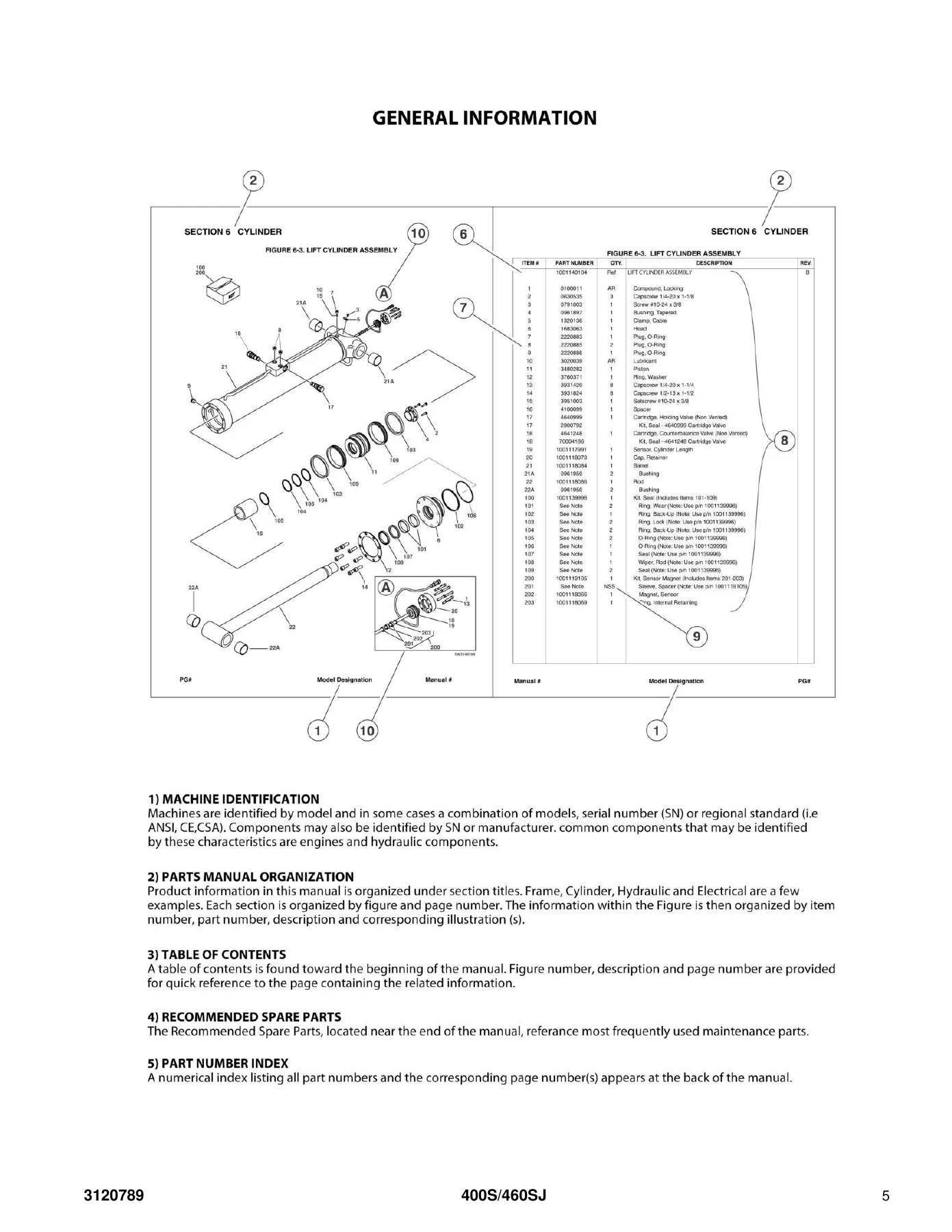
JLG 400S & 460SJ Illustrated Parts Manual 3120789 Rev AG - PDF Download — PDF page 5 preview
JLG 400S & 460SJ Illustrated Parts Manual 3120789 Rev AG - PDF Download — PDF page 81 preview
JLG 400S & 460SJ Illustrated Parts Manual 3120789 Rev AG - PDF Download — PDF page 215 preview

Why the Correct Parts Reference Matters

Parts on these machines change across production runs – axle weldments, drive hubs, steer cylinder assemblies, platform consoles, controllers and engine installations all have different versions keyed to serial numbers. Ordering the wrong revision means a part that does not fit or a repair that has to be redone. This 3120789 parts catalog is built around those breaks, showing which parts apply before and after each serial number threshold so the correct component is identified the first time. It also includes revision letters on individual parts lines, so you can see whether a component has been updated even within the same serial range.

Instant PDF Delivery

The JLG 400S and 460SJ illustrated parts manual is delivered as a downloadable PDF immediately after purchase. There is nothing to ship and nothing to wait for. The file opens on any device that reads PDFs and can be printed for the shop, so the pages you need for a specific job can be on the bench next to the machine while the rest stays on file. Whether you are identifying a single seal kit or working through a full hydraulic diagram, the 400S and 460SJ parts reference puts the correct information within reach.
Reviews

There are no reviews yet.

Be the first to review “JLG 400S & 460SJ Illustrated Parts Manual 3120789 Rev AG – PDF Download”

What Our Customers Say

★★★★★ Live reviews from customers
Loading customer reviews...
0
    0
    Your Cart
    Your cart is emptyReturn to Shop
    🛒
    Recently Purchased
    🕒 verified order