
JLG 4017 Service Manual P/N 3121858 – 2006 Telehandler Repair & Maintenance PDF
Original price was: $52.95.$34.95Current price is: $34.95.
Complete JLG 4017 Service Manual, P/N 3121858, revised January 6, 2006. 154-page PDF covering the four-section boom, Perkins 1004-40T engine, transmission, axles, hydraulic circuits, and electrical system – with torque values, wear limits, and step-by-step procedures.
Description
JLG 4017 Telehandler Service Manual – Complete Workshop Repair Guide
This is the complete JLG 4017 Service Manual, document number P/N 3121858, revised January 6, 2006. It is the same service and repair guide used by JLG-trained technicians to maintain, diagnose, disassemble, and rebuild the 4017 telehandler. Every procedure is tied to a specific system – from the four-section boom and Perkins diesel engine to the hydraulic circuits and electrical harnesses – with torque values, wear limits, and step-by-step teardown sequences printed alongside the component illustrations. Whether you are pulling a boom section, chasing a hydraulic pressure fault, or rebuilding a cylinder, this manual is the reference the job requires.
File Details
- Manual Type: Service Manual
- Brand: JLG
- Model: 4017
- Document Number: P/N 3121858
- Revision Date: January 6, 2006
- Language: English
- Page Count: 154
- File Format: PDF
Chapters Covered
- Section 1 – Safety Practices
- Section 2 – General Information and Specifications
- Section 3 – Boom
- Section 4 – Cab and Covers
- Section 5 – Axles, Drive Shafts, Wheels and Tires
- Section 6 – Transmission
- Section 7 – Engine: Perkins 1004-40T
- Section 8 – Hydraulic System
- Section 9 – Electrical System
Section 1 – Safety Practices
Establishes the safety framework every job depends on. Covers accident prevention tag procedures for the ignition key switch and steering wheel, personal and equipment hazard warnings, first-aid readiness, the DANGER/WARNING/CAUTION signal-word system, general and operational hazards including fluid temperature and pressure warnings, the emergency exit rear window procedure, and the safety decal check. Every subsequent procedure in the manual assumes you have read and understood this section first.
Section 2 – General Information and Specifications
Covers replacement parts and warranty information, machine serial number plate location, and then delivers the full fastener torque library – ASTM and metric charts for grade 2, 5, and 8 bolts plus metric class 8.8 and 10.9 fasteners. Travel speeds, engine performance figures including low and high idle settings, hydraulic cylinder cycle times, tire specifications with lug nut torque, axle part numbers, electrical fuse and relay assignments, fluid capacities for engine oil, coolant, transmission, axles, brakes, and hydraulic system, and the complete 8-hour through 1500-hour maintenance and lubrication schedules are all here. This is the section you will return to most often for specifications.
Section 3 – Boom
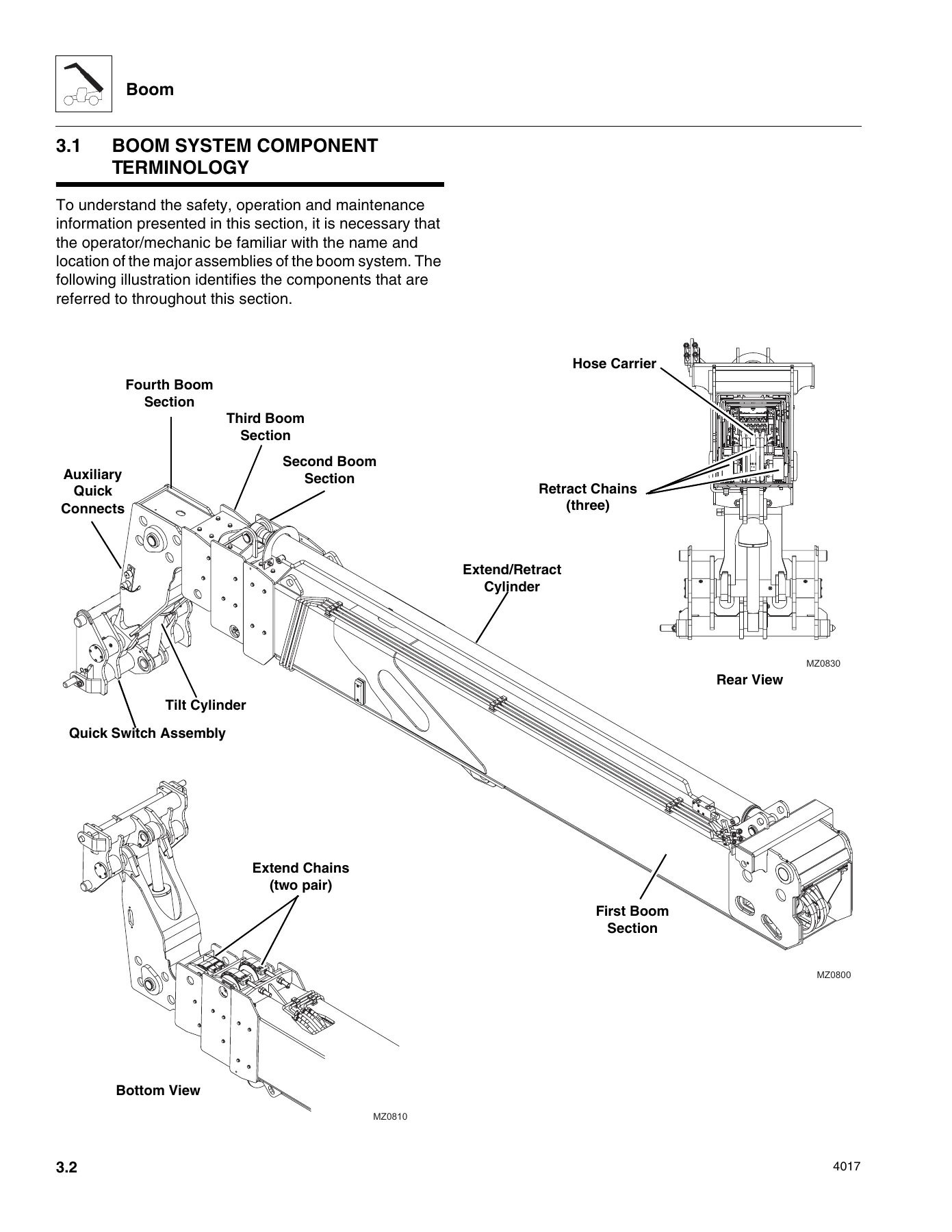
The largest single section of the manual and the heart of the 4017 telehandler service work. Details the four-section boom system, component terminology, and the full boom assembly maintenance sequence – removal of the second, third, and fourth boom sections, extend and retract chain inspection including elongation measurement across pin spans, boom section separation adjustment, hose carrier removal and installation, wear pad inspection and replacement with shimming procedures, quick switch assembly connection and removal, and a dedicated boom troubleshooting guide. Chain inspection criteria include edge wear limits and elongation limits with specific measurements for both fourth-to-third and third-to-second section chains. The section also covers chain lubrication requirements and the complete boom removal and installation sequence with torque values for every mounting bolt and wear pad.
Section 4 – Cab and Covers
Component terminology for the operator’s cab, steering column and orbitrol valve service, service brake and throttle pedal removal and installation with adjustment procedures, joystick assembly removal and installation with function testing, windshield wiper assembly reference, heater/defroster system including heater assembly removal and installation with coolant draining and filling, and complete cab removal and installation procedures. Cab safety warnings regarding ROPS/FOPS protection are included.
Section 5 – Axles, Drive Shafts, Wheels and Tires
Axle assemblies with serial number plate location and specifications, Dana-Spicer axle maintenance including cleaning, drying, and periodic operation requirements, drive shaft inspection and service with universal joint and cross bearing inspection criteria, wheel and tire removal and installation with torque values, brake disc inspection with wear limits, and the towing a disabled machine procedure including manual park brake release and reset with specific bolt turn dimensions. Axle assembly and drive shaft troubleshooting charts cover excessive noise, vibration, oil leaks, overheating, steering effort, and brake problems.
Section 6 – Transmission
Transmission component terminology, serial number location, specifications, maintenance schedule, and the complete transmission replacement procedure – removal with all mounting bolt torques, inspection, installation with torque converter and flex plate alignment, and after-service checks including oil cooler back-flushing. Includes transmission troubleshooting charts covering shifting problems, low pump pressure, clutch pressure, power loss, overheating, grinding noises, and oil leaks with specific remedies.
Section 7 – Engine: Perkins 1004-40T
Full engine coverage for the Perkins 1004-40T: serial number location, specifications, cooling system including radiator pressure cap, thermostat replacement, and radiator/oil cooler service with draining and filling procedures, engine electrical system reference, fuel system including diesel fuel specifications and fuel tank removal and installation, exhaust system removal and installation, air cleaner assembly service, complete engine removal and installation with lifting and alignment procedures, engine drive plate removal and installation with torque values, and a comprehensive troubleshooting chart with keyed possible causes covering low cranking power, will not start, lack of power, misfiring, excessive fuel consumption, black and blue/white exhaust, low oil pressure, knocking, vibration, overheating, and more.
Section 8 – Hydraulic System
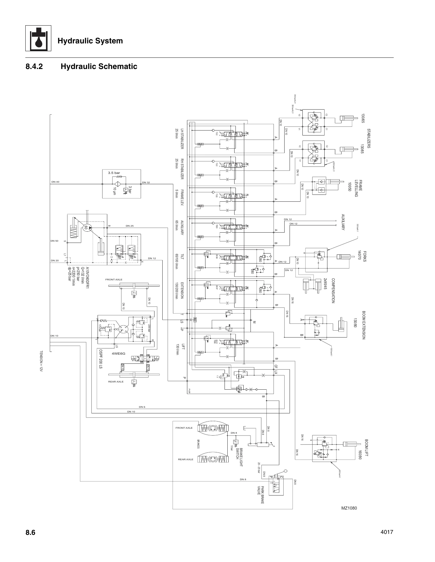
Hydraulic component terminology, safety information, pressure diagnosis, hydraulic circuits with pressure checking and adjustment procedures, the full hydraulic schematic with all valve sections and cylinder circuits, reservoir draining and service, engine implement pump description and replacement including pump failure analysis, main control valve service with complete disassembly and assembly procedures for all seven working sections, service brake valve, park brake valve, steering orbitrol valve, steer select valve and manifold service, hydraulic cylinder general removal, disassembly, inspection, assembly and installation with torque specifications for lift, extend/retract, tilt, compensation, sway, and outrigger cylinders.
Section 9 – Electrical System
Electrical component terminology, service warnings including ESX control module precautions for welding, fuse and relay locations and replacement with complete connector legend, cab harness, engine harness, printed circuit board, ESX harness and options, and front and rear chassis harness electrical schematics, circuit breakdowns for constant power, start, and charging circuits, starter and alternator service with testing and removal procedures, wiper and washer systems, cab heater and fan controls, solenoids and senders including fuel shut-off, main control valve, transmission shift solenoids, transmission temperature and speed sensors, engine oil pressure and coolant temperature senders, fuel level sender, boom angle sensor with learning calibration, load moment indicator and sensor with calibration, front and rear axle proximity sensors, display monitor and gauges, joystick, dash switches including ignition key switch testing, and transmission control lever replacement.
What This JLG 4017 Service Manual Enables You to Do
This JLG 4017 service manual gives you the complete procedure for every major repair on the machine: pulling and re-installing all four boom sections, replacing extend and retract chains, adjusting boom separation, servicing the Perkins 1004-40T engine, removing and installing the transmission, diagnosing hydraulic pressure faults, tracing electrical circuits through the harness schematics, and rebuilding hydraulic cylinders with the correct torque values. Whether you are a shop technician performing a scheduled 1000-hour service or an owner diagnosing a boom that will not extend, the manual provides the sequence, the specifications, and the diagrams to do the job correctly.
Every torque value, wear limit, and adjustment dimension is printed as a specific number – not a general range. Boom wear pad gaps, chain elongation limits, cylinder piston head torque, axle oil capacities, battery and alternator ratings, hydraulic system pressure – they are all here, so you are not guessing or looking up a second source. The component terminology illustrations at the start of each section mean you can identify exactly which part the procedure is referring to before you start turning wrenches. The troubleshooting charts in Sections 3, 5, 6, 7, and 9 give you a fast path from symptom to cause to remedy when a fault code or performance issue appears.
IMAGES PREVIEW
Instant PDF Download – No Shipping, No Waiting
Your JLG 4017 telehandler repair manual is available immediately after payment. No shipping, no waiting for a physical book. The PDF opens on any device – desktop, laptop, tablet, or phone – and every page is printable, so you can take the relevant section into the shop or keep the full manual on a tablet at the machine. Bookmark it once and you have the complete JLG 4017 service reference at your fingertips. This is the manual you keep for the life of the machine.

Reviews
There are no reviews yet.