★ TRUSTED BY 321,897+ PROFESSIONALS WORLDWIDE
🏒
Trusted Business
Verified & Licensed
πŸ›‘οΈ
Virus Free Files
100% Safe Downloads
πŸ”’
Secure Payment
SSL Protected
⚑
Instant Delivery
Available Immediately
Sale!

JLG 450A & 450AJ Series II Service and Maintenance Manual – P/N 3121180 PDF (2010)

Original price was: $39.95.Current price is: $23.95.

Complete JLG 450A and 450AJ Series II Service and Maintenance Manual (P/N 3121180, December 2010). Covers chassis, turntable, boom, platform, hydraulics, JLG control system, engines (Ford, Deutz, Caterpillar, GM, Perkins), diagnostic trouble codes, and electrical/hydraulic schematics.

⚑
Instant PDF Download
Available immediately
πŸ’Ύ
Save to Your Device
Download & keep forever
πŸ›‘οΈ
Antivirus Scanned
100% virus-free
🌍
Trusted Worldwide
175,000+ customers

Description

JLG 450A & 450AJ Series II Service and Maintenance Manual – P/N 3121180

The JLG 450A & 450AJ Series II Service and Maintenance Manual (P/N 3121180, dated December 22, 2010) is the comprehensive workshop reference for the JLG 450A and 450AJ Series II aerial work platforms. This JLG 450A/450AJ Series II service manual spans every major system on the machine – from chassis and turntable through the boom and platform, hydraulics, the JLG control system, and full electrical/hydraulic schematics. Whether you are diagnosing a fault code, rebuilding a torque hub, setting hydraulic pressures, or servicing one of the six engine variants offered for these models, this 3121180 service manual gives you the procedures, specifications, and illustrations required to do the job correctly.

File Details

  • Manual type: Service and Maintenance Manual
  • Brand: JLG Industries, Inc.
  • Models covered: 450A Series II, 450AJ Series II
  • Document number: P/N 3121180
  • Date: December 22, 2010
  • Language: English
  • File format: PDF

Chapters Covered

  • Section A – Introduction: Maintenance safety precautions, general warnings, hydraulic system safety, mandatory maintenance practices.
  • Section 1 – Specifications: Capacities, tires, engine data, reach specifications, dimensional data, chassis specifications, function speeds, torque requirements, lubrication (hydraulic oil, greases), major component weights, pressure settings, serial number locations, operator maintenance schedule, propane fuel system maintenance and pressure relief.
  • Section 2 – General: Machine preparation, inspection and maintenance, pre-start inspection, pre-delivery and frequent inspection, annual machine inspection, preventative maintenance, service guidelines, cleanliness, component removal and installation, disassembly and reassembly, pressure-fit parts, bearings, gaskets, bolt usage and torque application, hydraulic lines and electrical wiring, lubrication, battery, cylinder drift test, pins and composite bearing repair guidelines, welding on JLG equipment, inspection and preventive maintenance schedule, engine operating temperature specifications.
  • Section 3 – Chassis & Turntable: Tires and wheels, wheel installation, torque hub (machines built before S/N 0300071527 and after), roll/leak/brake testing, drive motor disassembly and inspection, loop flushing valve, lockout valve adjustment, oscillating axle bleeding and lockout test, swing bearing removal and assembly, swing bearing wear tolerance and torque values, semi-track testing and adjustment, generator service, Ford EFI engine diagnostics and sensors, Deutz engine maintenance (oil, filters, fuel strainer), Deutz EMR 2 diagnostic support, GM engine general maintenance and dual fuel system, Perkins engine maintenance, DGC diagnostic support and trouble code definitions (ECT, TPS, MAP, oil pressure, battery voltage, microprocessor faults, CAN J1939 faults).
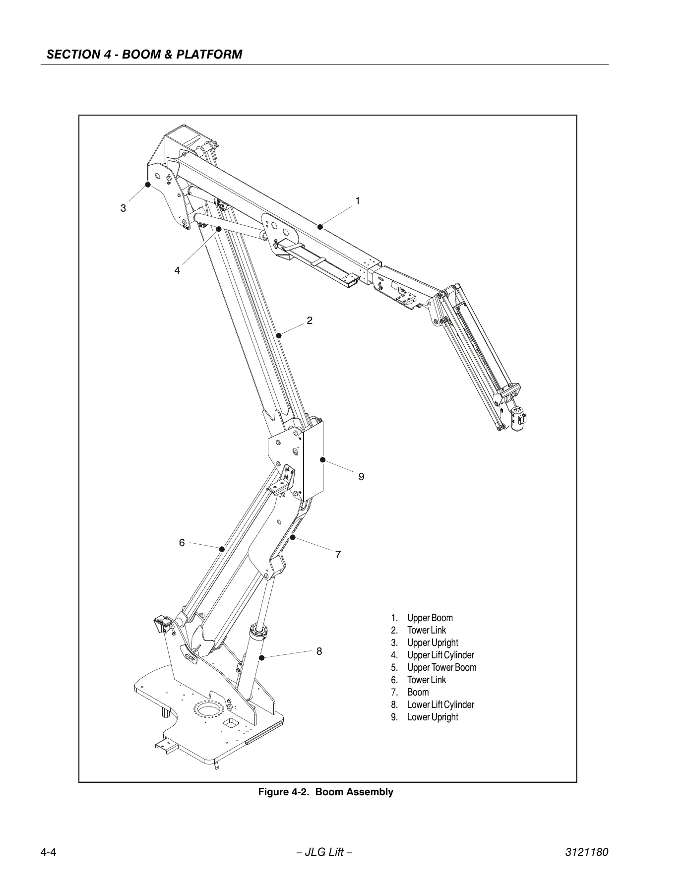
  • Section 4 – Boom & Platform: Boom maintenance, boom assembly removal, main boom disassembly and assembly, boom inspection, rotator theory of operation and repair, rotary actuator (S/N 0300130812 and 1300006433 to present) disassembly, inspection, assembly and counterbalance valve installation.
  • Section 5 – Hydraulics: Cylinder repair (disassembly, cleaning and inspection, assembly), hydraulic pump (gear) disassembly and inspection, variable pump (ports and pressure gauges, NFPE control, charge relief valve, shaft seal and shaft replacement, charge pump), hydraulic component start-up procedures, pressure setting procedure (bang-bang main relief, steer, platform level up/down, articulating jib, proportional main relief, lift down, swing).
  • Section 6 – JLG Control System: Hand held analyzer connection and use, changing access level, adjusting parameters, machine setup, machine personality settings, system test from platform and ground station, diagnostics parameters and fault code tables.
  • Section 7 – Basic Electrical Information & Schematics: Multimeter basics (voltage, resistance, continuity, current), applying silicone dielectric compound, AMP connectors, Deutsch connectors, electrical component installation, electrical schematics (Deutz EMR2, GM, CAT engines), hydraulic schematics.

IMAGES PREVIEW

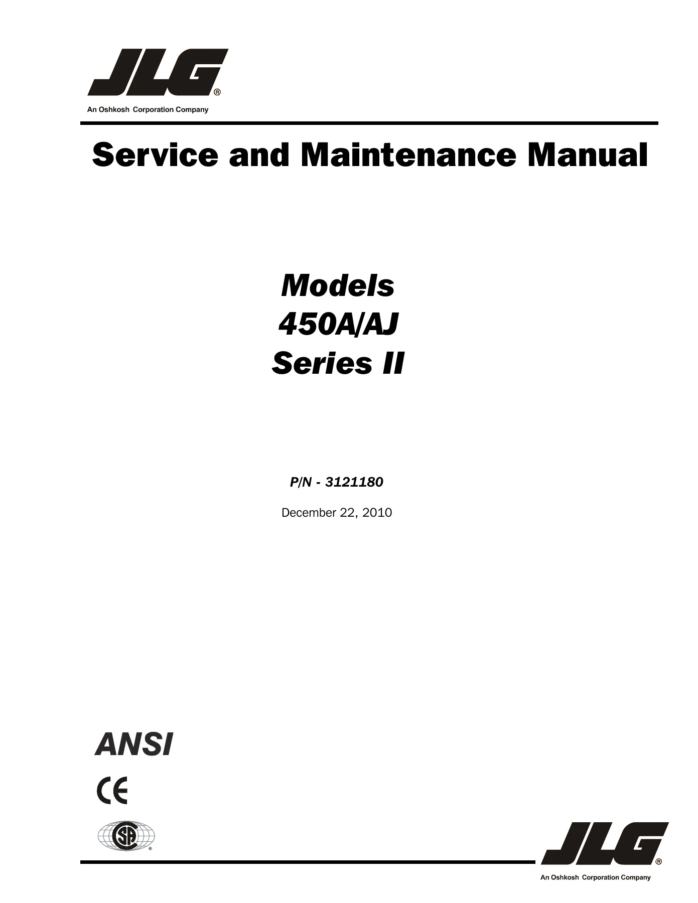
JLG 450A & 450AJ Series II Service and Maintenance Manual - P/N 3121180 PDF (2010) β€” PDF page 1 preview
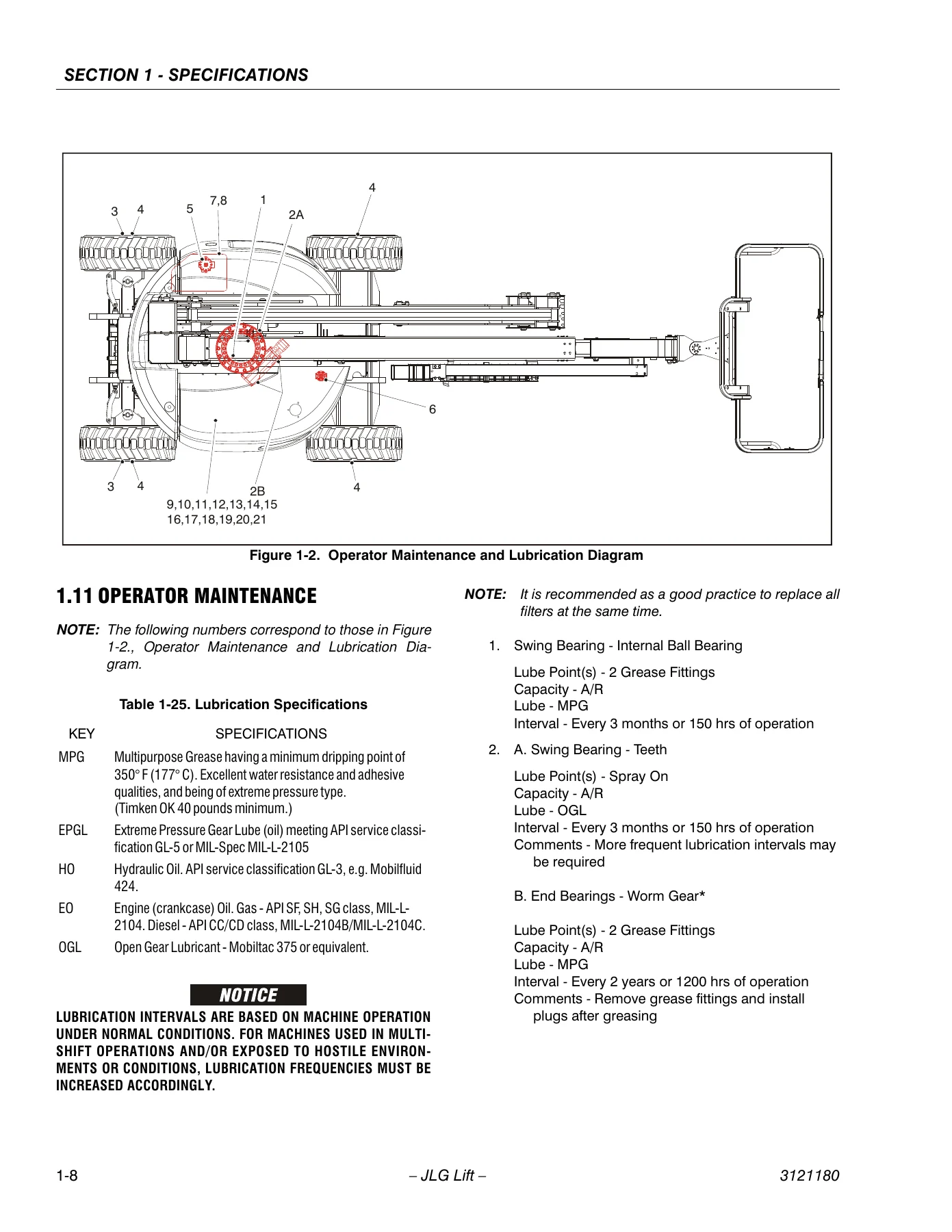
JLG 450A & 450AJ Series II Service and Maintenance Manual - P/N 3121180 PDF (2010) β€” PDF page 26 preview
JLG 450A & 450AJ Series II Service and Maintenance Manual - P/N 3121180 PDF (2010) β€” PDF page 268 preview

What This JLG 450A/450AJ Service Manual Gives You

This is not a generic lift manual. The 450A & 450AJ Series II service manual is model-specific and serial-number-aware, with procedures split by machine build ranges (e.g., torque hubs before and after S/N 0300071527, oscillating axle cylinders for USA and Belgium built machines, swing bearing procedures with specific torque sequences). Across its 400+ pages you get exploded assembly drawings, hydraulic and electrical schematics, torque charts for SAE and metric fasteners, pressure settings for every function, cylinder drift limits, wear tolerances, and diagnostic trouble code tables that let you troubleshoot the engine and control system from the analyzer display.

Because the manual covers six engine platforms – Ford LRG-425 (gas/dual fuel), Deutz F3M1011F, Deutz F3M2011F, Caterpillar 3024/C2.2, GM 3.0L, and Perkins 404C-22 – it serves machines regardless of which powerplant was fitted. The GM dual fuel system section alone walks through the Electric Pressure Regulator (EPR), low pressure regulator, air fuel mixer, electronic throttle control, and the complete LPG fuel system diagnosis tables.

Complete PDF Bookmark Tree

Complete Bookmarks

The complete bookmarks in the β€œJLG 450A & 450AJ Series II Service and Maintenance Manual – P/N 3121180 PDF (2010)” are as follows:

Section A. INTRODUCTION – MAINTENANCE SAFETY PRECAUTIONSp. 3
A Generalp. 3
B Hydraulic System Safetyp. 3
C Maintenancep. 3
Section 1. Specificationsp. 19
1.1 Capacitiesp. 19
1.2 Tiresp. 19
1.3 Enginep. 19
1.4 Specifications and Performance Datap. 20
Reach Specificationsp. 20
Dimensional Datap. 20
Chassisp. 20
1.5 Function Speedsp. 21
Machine Orientation When Doing Speed Testsp. 21
Test Notesp. 21
1.6 Torque Requirementsp. 21
1.7 Lubricationp. 23
Hydraulic Oilp. 23
1.8 Major Component Weightsp. 24
1.9 Pressure Settings – PSI (BAR)p. 24
1.10 Serial Number Locationp. 25
1.11 Operator Maintenancep. 26
1.12 Draining Oil Build Up From The Propane Regulator (Prior to S/N 0300137808)p. 30
1.1 Propane Fuel Filter Replacementp. 31
Removalp. 31
Installationp. 32
1.13 Propane Fuel System Pressure Reliefp. 32
Section 2. Generalp. 41
2.2 Machine Preparation, Inspection, and Maintenancep. 41
Generalp. 41
Preparation, Inspection, and Maintenancep. 41
Pre-Start Inspectionp. 41
Pre-Delivery Inspection and Frequent Inspectionp. 41
Annual Machine Inspectionp. 41
Preventative Maintenancep. 41
2.3 Service and Guidelinesp. 42
Generalp. 42
Safety and Workmanshipp. 42
Cleanlinessp. 42
Components Removal and Installationp. 42
Component Disassembly and Reassemblyp. 43
Pressure-Fit Partsp. 43
Bearingsp. 43
Gasketsp. 43
Bolt Usage and Torque Applicationp. 43
Hydraulic Lines and Electrical Wiringp. 43
Hydraulic Systemp. 43
Lubricationp. 43
Batteryp. 43
Lubrication and Servicingp. 43
2.4 Lubrication and Informationp. 44
Hydraulic Systemp. 44
Hydraulic Oilp. 44
Changing Hydraulic Oilp. 44
Lubrication Specificationsp. 44
2.5 Cylinder Drift Testp. 45
Platform Driftp. 45
Cylinder Driftp. 45
2.6 Pins and Composite Bearing Repair Guidelinesp. 45
2.7 Welding on JLG Equipmentp. 46
Do the Following When Welding on JLG Equipmentp. 46
Do NOT Do the Following When Welding on JLG Equipmentp. 46
Section 3. Chassis & Turntablep. 55
3.1 Tires & Wheelsp. 55
Tire Inflationp. 55
Tire Damagep. 55
Tire Replacementp. 55
Wheel Replacementp. 55
Wheel Installationp. 56
3.2 Torque Hub (Machines built Before S/N 0300071527)p. 57
Roll, Leak and Brake Testingp. 57
Tightening and Torquing Boltsp. 57
Main Disassemblyp. 58
Input Carrier Disassemblyp. 60
Output Carrier Disassemblyp. 61
Housing-Spindle Disassemblyp. 62
Spindle-Brake Disassemblyp. 63
Input Carrier Sub-Assemblyp. 64
Output Carrier Sub-Assemblyp. 66
Spindle-Brake Sub-Assemblyp. 68
Housing-Spindle Sub-Assemblyp. 70
DW2B INTEGRAL BRAKE CHECKp. 70
Main Assemblyp. 72
3.3 Torque Hub (Machines built after S/N 0300071527)p. 84
Roll and Leak Testingp. 84
Tightening and Torquing Boltsp. 84
Oil Informationp. 84
MAIN DISASSEMBLY for ”B” Drivesp. 84
Hub-Spindle Disassemblyp. 85
Cover Disassemblyp. 85
Carrier Disassemblyp. 85
Assembly of the Carrierp. 86
Cover Sub-Assemblyp. 88
Hub-Spindle Sub-Assemblyp. 89
Main Assemblyp. 91
Tool Listp. 96
3.4 Re-Aligning Torque Hub Input Couplingp. 97
Equipment Requiredp. 97
Procedurep. 97
3.5 Drive Motorp. 97
Disassemblyp. 97
Inspectionp. 98
Assemblyp. 100
Drive Motor Troubleshootingp. 101
3.6 Drive Motorp. 102
Descriptionp. 102
Shaft Seal Replacementp. 102
Loop Flushing Valvep. 103
Troubleshootingp. 104
Disassemblyp. 105
Inspectionp. 109
Assemblyp. 111
Initial Start-up Proceduresp. 116
3.7 Adjustment Procedure For Lockout Valvep. 119
3.8 Oscillating Axle Bleeding Procedure and Lockout Testp. 119
Lockout Cylinder Bleeding (Early Cylinders)p. 119
Lockout Cylinder Bleeding (Ram Cylinders)p. 120
Oscillating Axle Lockout Testp. 120
3.9 Swing Bearingp. 121
Descriptionp. 121
Removalp. 121
Disassemblyp. 121
Assemblyp. 124
Installationp. 124
Turntable Bearing Mounting Bolt Condition Checkp. 125
Wear Tolerancep. 126
Swing Bearing Torque Valuep. 126
3.10 Semi-Trackp. 127
Testing the Trackp. 127
Removing the Trackp. 127
Assuming Normal Wearp. 127
Adjustmentp. 128
3.11 Generatorp. 132
Every 250 hoursp. 132
Every 500 hoursp. 132
Overload Protectionp. 132
Inspecting Brushes, Replacing Brushes, and Cleaning Slip Ringsp. 132
3.12 Ford EFI Enginep. 134
Performing Diagnosticsp. 134
EFI Diagnosticsp. 135
ECM and Sensorsp. 135
Fuel Systemp. 142
3.13 Deutz Enginep. 146
Checking Oil Levelp. 146
Changing Engine Oilp. 146
Changing the Oil Filterp. 147
Replacing the Fuel Filterp. 147
Cleaning the Fuel Strainerp. 148
3.14 Deutz EMR 2 (S/N 85332 to Present)p. 148
3.15 GM Engine General Maintenancep. 161
Maintenance of the Drive Beltp. 161
Engine Electrical System Maintenancep. 161
Checking/Filling Engine Oil Levelp. 161
Changing The Engine Oilp. 162
Coolant Fill Procedure – Dual Fuel Enginep. 162
3.16 GM Engine Dual Fuel Systemp. 163
Fuel Filterp. 164
Electric Lock Offp. 164
EPR Assemblyp. 164
Low Pressure Regulator (LPR)p. 165
Air Fuel Mixerp. 165
Electronic Throttle Control (ETC)p. 166
Engine Control Modulep. 166
Heated Exhaust Gas Oxygen Sensorp. 167
Gasoline Multi Point Fuel Injection System (MPFI)p. 167
Gasoline Fuel Pumpp. 167
Gasoline Pressure And Temperature Sensor Manifoldp. 167
Fuel Filterp. 168
Fuel Injector Railp. 168
Fuel Injectorp. 168
3.17 GM Engine Fuel System Repairp. 168
Propane Fuel System Pressure Reliefp. 168
Propane Fuel System Leak Testp. 168
Propane Fuel Filter Replacementp. 169
Removalp. 169
Installationp. 169
Electronic Pressure Regulator (EPR) Assembly Replacementp. 170
Temperature Manifold Absolute Pressure (TMAP) Sensorp. 171
Electronic Throttle Control Replacementp. 172
MIXER REPLACEMENTp. 173
Coolant Hose Replacementp. 173
Vapor Hose Replacementp. 173
Engine Control Module Replacementp. 173
Heated Exhaust Gas Oxygen Sensor Replacementp. 173
3.18 GM Engine LPG Fuel System Diagnosisp. 174
Fuel System Descriptionp. 174
Diagnostic Aidsp. 174
3.19 Perkins Engine General Maintenancep. 190
Replacing the Engine Crankcase Breatherp. 190
Engine Oil Level – Checkp. 190
Engine Oil and Filter – Changep. 190
Fuel Filter/Water Separatorp. 192
Setting the Actuatorp. 193
Speed Sensor Installationp. 194
3.20 Engine Radiator Fill Procedure – Perkins & Caterpillarp. 194
3.21 DGC DIAGNOSTIC SUPPORT AND TROUBLE CODE DEFINITIONSp. 196
Section Layoutp. 196
List of Abbreviations in this Sectionp. 197
Fault Code Broadcastp. 198
Diagnostic Trouble Codesp. 198
CANp. 198
MIL Outputp. 199
Diagnostic Calibration Configuration and Corrective Actionsp. 199
Fault/Diagnostic Trouble Code Interactionp. 200
DBW Diagnostic Testp. 205
3.22 Diagnostic Trouble Code Fault Descriptionsp. 206
DTC 116- ECT Higher Than Expected Stage 1p. 206
DTC 117- ECT/CHT Low Voltagep. 207
DTC 118- ECT/CHT High Voltagep. 209
DTC 122- TPS1 Signal Voltage Lowp. 211
DTC 123- TPS1 Signal Voltage Highp. 214
DTC 217- ECT Higher Than Expected 2p. 216
DTC 219- RPM Higher Than Max Allowed Governed Speedp. 217
DTC 336- Crank Signal Input Noisep. 218
DTC 337- Loss of Crank Input Signalp. 220
DTC 521- Oil Pressure Sender/Switch High Pressurep. 221
DTC 524- Oil Pressure Lowp. 224
DTC 562- Battery Voltage (VBat) Lowp. 228
DTC 563- Battery Voltage (VBat) Highp. 230
DTC 601- Microprocessor Failure – FLASHp. 232
DTC 604- Microprocessor Failure – RAMp. 234
DTC 606- Microprocessor Failure – COPp. 236
DTC 642- 5 Volt External Low Voltagep. 238
DTC 643- 5 Volt External High Voltagep. 240
DTC 1612- Microprocessor Failure – RTI 1p. 242
DTC 1613- Microprocessor Failure – RTI 2p. 243
DTC 1614- Microprocessor Failure – RTI 3p. 245
DTC 1615- Microprocessor Failure – A/Dp. 247
DTC 1616- Microprocessor Failure – interruptp. 249
DTC 1625- CAN J1939 Shutdown Requestp. 251
DTC 1626- CAN J1939 Transmit (Tx) Faultp. 252
DTC 1627- CAN J1939 Receive (Rx) Faultp. 253
DTC 1628- CAN Address Conflict Failurep. 254
DTC 1629- J1939 TSC1 Message Reciept Lossp. 256
DTC 1652- TPS1 Loss of Communicationsp. 257
DTC 2111- Unable to Reach Lower TPSp. 258
DTC 2112- Unable to Reach Higher TPSp. 260
DTC 9999- Throttle Actuator Failsafe Spring Failurep. 261
DTC to SPN/FMI Tablep. 262
Section 4. Boom & Platformp. 265
4.1 Boom Maintenancep. 265
Removal of the Boom Assemblyp. 265
Disassembly of the Main Boomp. 266
Inspectionp. 266
Assembly of the Main Boomp. 267
Installation of the Boom Assemblyp. 267
4.2 Rotatorp. 272
Theory of Operationp. 272
Disassembly and Inspectionp. 272
Assembly and Testingp. 272
4.3 Rotary Actuator (S/N 0300130812 and 1300006433 to Present)p. 275
Theory of Operationp. 275
Required Toolsp. 275
Disassemblyp. 278
Inspectionp. 282
Assemblyp. 282
Installing Counterbalance Valvep. 287
Section 5. Hydraulicsp. 289
5.1 Cylinder Repair -USA Manufactured Onlyp. 289
Disassemblyp. 289
Cleaning and Inspectionp. 310
Assemblyp. 311
5.2 Hydraulic Pump (Gear)p. 314
Disassemblyp. 314
Inspect Parts For Wearp. 316
General Informationp. 317
Reverse Shaft Rotation of Pumpp. 317
Assemblyp. 317
Placing Pump Back Into Servicep. 320
5.3 Variable Pumpp. 320
Ports and Pressure Gaugesp. 320
NFPE Controlp. 320
Removal and Installation of FNR and NFPE Modulesp. 321
Removal and Installation of FNR and NFPE Control Orificesp. 321
Charge Relief Valvep. 321
Shaft Seal and Shaft Replacementp. 324
Charge Pumpp. 326
5.4 Hydraulic Component Start-Up Procedures and Recommendationsp. 328
5.5 Pressure Setting Procedurep. 330
Bang-Bang Main Reliefp. 330
Steerp. 330
Platform Level Upp. 330
Platform Level Downp. 330
Articulating Jibp. 330
Proportional Main Reliefp. 330
Lift Downp. 330
Swingp. 330
Section 6. JLG Control Systemp. 335
6.1 Introductionp. 335
6.2 To Connect the JLG Control System Analyzerp. 337
6.3 Using the Analyzerp. 337
6.4 Changing the Access Level of the Hand Held Analyzerp. 339
6.5 Adjusting Parameters Using the Hand Held Analyzerp. 341
6.6 Machine Setupp. 341
6.7 Machine Personality Settingsp. 350
6.8 System Testp. 370
Test from the Platformp. 370
Test from the Ground Stationp. 372
Section 7. Basic Electrical Information & schematicsp. 413
7.1 Generalp. 413
7.1 Multimeter Basicsp. 413
Groundingp. 413
Backprobingp. 413
Min/Maxp. 413
Polarityp. 413
Scalep. 413
Voltage Measurementp. 413
Resistance Measurementp. 414
Continuity Measurementp. 414
Current Measurementp. 415
7.2 Applying Silicone Dielectric Compound to Electrical Connectionsp. 415
7.3 AMP Connectorp. 416
Applying Silicone Dielectric Compound to AMP Connectorsp. 416
Assemblyp. 416
Disassemblyp. 418
Wedge Lockp. 418
Service – Voltage Readingp. 418
7.4 Deutsch Connectorsp. 420
DT/DTP Series Assemblyp. 420
DT/DTP Series Disassemblyp. 420
HD30/HDP20 Series Assemblyp. 421
HD30/HDP20 Series Disassemblyp. 421

Why Correct Procedures and Specs Matter

Aerial work platforms are safety-critical machines. Incorrect torque on a swing bearing bolt, an improperly bled oscillating axle cylinder, or a misadjusted lockout valve can lead to structural failure or loss of stability. This JLG 450A Series II repair manual provides the exact values and sequences JLG specifies: swing bearing bolts at 240 ft. lbs. after a 175 ft. lbs. initial pass, wheel lugs at 170 ft. lbs., hydraulic system pressures from 1200 psi lift down to 3300 psi bang-bang main relief, and cylinder drift limits measured in thousandths of an inch. Following these specifications protects both the machine and the technician.

Instant PDF Delivery

The JLG 450A & 450AJ Series II Service and Maintenance Manual P/N 3121180 is delivered as an instant PDF download – no shipping, no waiting. Access it on any device, print the sections you need for the shop, and keep the full manual on hand for every service interval. Whether you are a fleet maintenance manager, an independent aerial lift technician, or an owner-operator keeping a 450A/450AJ in service, this manual is the reference you will reach for before every repair.
Reviews

There are no reviews yet.

Be the first to review “JLG 450A & 450AJ Series II Service and Maintenance Manual – P/N 3121180 PDF (2010)”

What Our Customers Say

β˜…β˜…β˜…β˜…β˜… Live reviews from customers
Loading customer reviews...
0
    0
    Your Cart
    Your cart is emptyReturn to Shop
    πŸ›’
    Recently Purchased
    πŸ•’ verified order