★ TRUSTED BY 321,897+ PROFESSIONALS WORLDWIDE
🏢
Trusted Business
Verified & Licensed
🛡️
Virus Free Files
100% Safe Downloads
🔒
Secure Payment
SSL Protected
Instant Delivery
Available Immediately
Sale!

JLG 600A & 600AJ Boom Lift Illustrated Parts Manual – 3121206 Rev AO PDF Download

Original price was: $34.95.Current price is: $20.95.

Complete 532-page illustrated parts catalog for JLG 600A and 600AJ telescopic boom lifts. Exploded-view diagrams and itemised part lists for every assembly. Covers USA-built (SN prefix 03) and China-built (SN prefix B3) machines, Caterpillar, Deutz, Ford and GM engines. Instant PDF download.

SKU: JLG-600A-600AJ-IPM-3121206-HD Category: Tags: , , , Vendor: Clutch Manuals
Instant PDF Download
Available immediately
💾
Save to Your Device
Download & keep forever
🛡️
Antivirus Scanned
100% virus-free
🌍
Trusted Worldwide
175,000+ customers

Description

JLG 600A & 600AJ Illustrated Parts Manual

This JLG 600A & 600AJ Illustrated Parts Manual is the complete illustrated parts catalog for JLG 600A and 600AJ telescopic boom lifts, published under document number 3121206 and current to Revision AO dated December 18, 2018. Every assembly is broken down into exploded-view illustrations paired with itemised parts lists, giving you exact part numbers, descriptions and quantities for identifying, verifying and ordering components.

File Details

  • Manual type: Illustrated Parts Manual
  • Brand: JLG Industries
  • Models covered: 600A, 600AJ
  • Document number: 3121206
  • Revision: AO (December 18, 2018)
  • Language: English
  • Page count: 532
  • File format: PDF

IMAGES PREVIEW

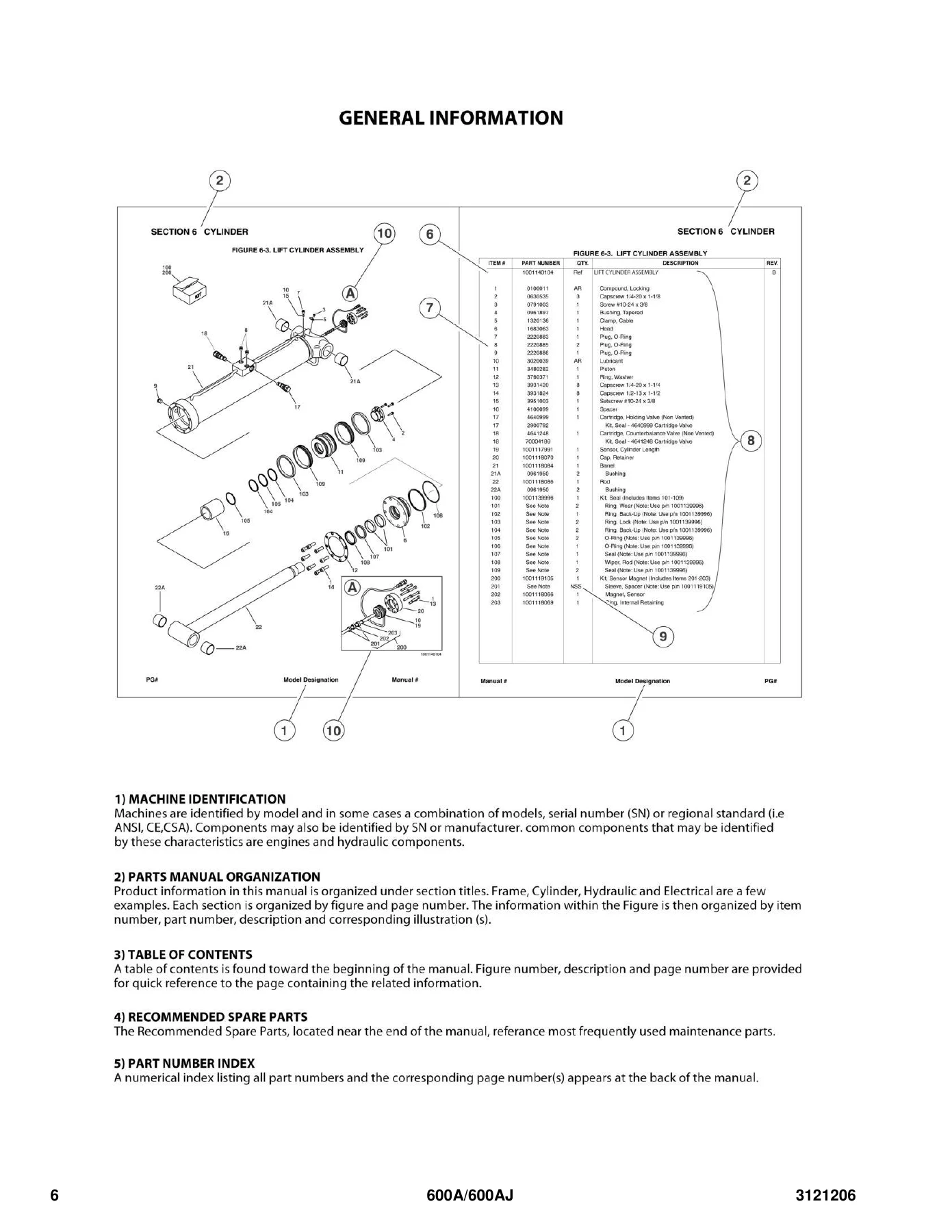
JLG 600A & 600AJ Boom Lift Illustrated Parts Manual - 3121206 Rev AO PDF Download — PDF page 6 preview
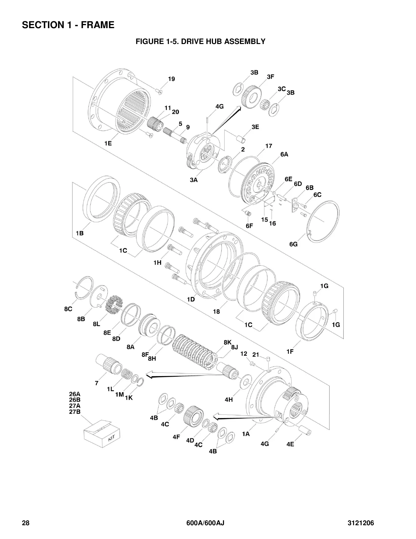
JLG 600A & 600AJ Boom Lift Illustrated Parts Manual - 3121206 Rev AO PDF Download — PDF page 28 preview
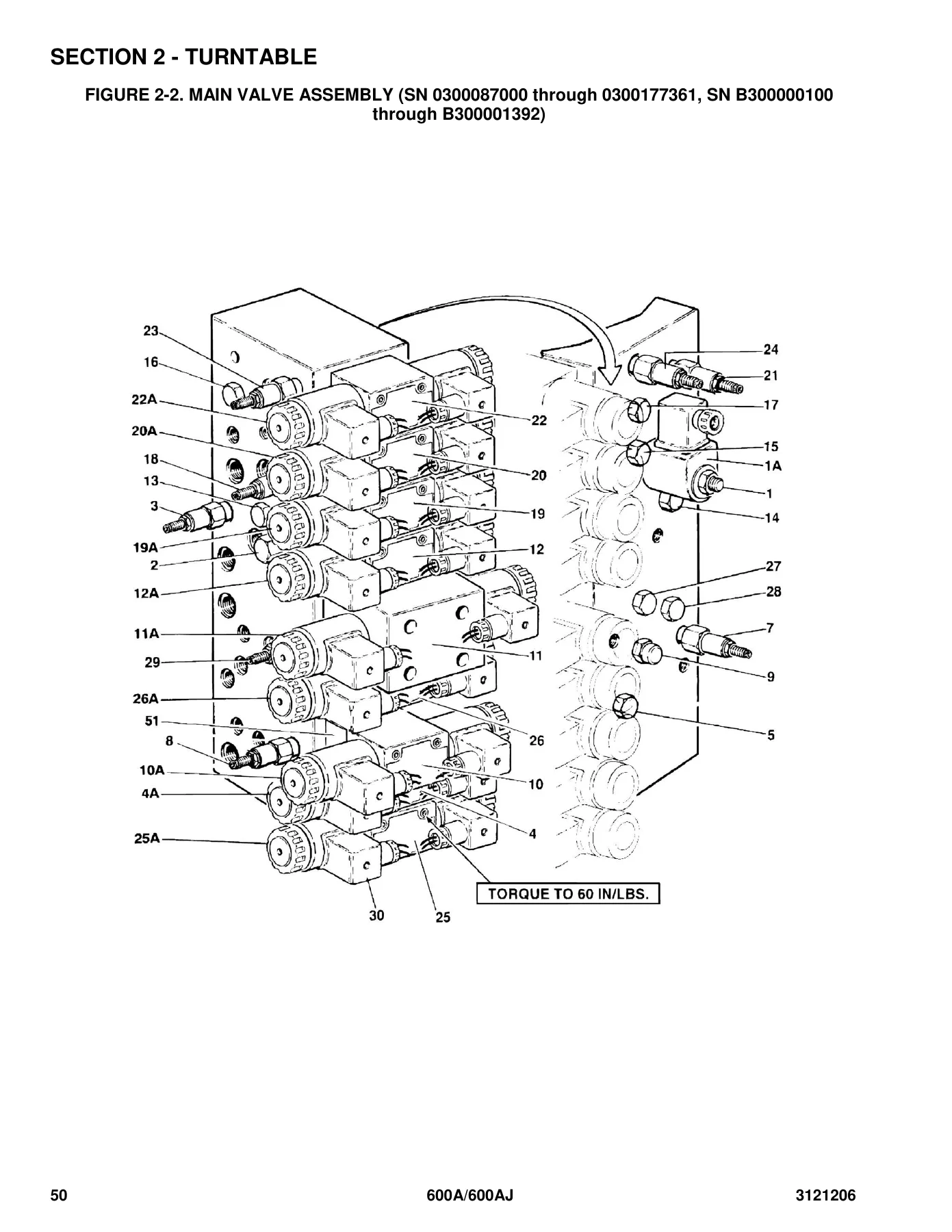
JLG 600A & 600AJ Boom Lift Illustrated Parts Manual - 3121206 Rev AO PDF Download — PDF page 50 preview

Chapters Covered

  • Section 1 – Frame: 2WD front axle and steering installations, 4WD front axle and steering installations, 4WS rear steering installations, tire and wheel drive installations, drive hub assembly, drive motor assembly (original equipment and service replacement), drive valves and shields, tow package installation.
  • Section 2 – Turntable: Control valves installations, main valve assembly (multiple serial ranges), accessory valve assemblies, swing drive/turntable bearing and lock, swing hub assembly, swing motor assemblies (White Roller Stator, Parker, Parker/Fairfield), Caterpillar engine installation (Tier II, Tier III/IV, Tier IVi), Deutz engine installation, Ford engine installation, GM engine installation, piston pump assembly, gear pump assembly, tank installations, rotary coupling installations, ground control box assembly (with and without UGM), electrical options, engine tray jack, hoods installations, 2500W generator installations, 4000W generator installation, 7500W SkyPower generator installations.
  • Section 3 – Boom: USA-built and China-built booms and cylinders installations for 600A and 600AJ, tower boom assembly, main boom assembly, rotator assemblies, platform support installation with LSS, valves and switches (boom mounted).
  • Section 4 – Platform: Platform assemblies with gate and drop-bar, fall-arrest platform components, platform console assembly (without and with SkyGuard), lift and swing controllers, drive and steer controllers, SkyEye installation, SkyGuard system installation, SkyLine installation, cross rail installation, platform padding, soft-touch system, SkyGlazier installation (2005-2007 and 2008-2013), SkyWelder/SkyCutter combo, SkyWelder (50Hz and 60Hz), SkyWelder prep package, welder assembly, SkyWelder locking bracket, SkyCutter installation, plasma cutter assembly, pipe racks installation.
  • Section 5 – Cylinder: Axle lockout cylinder assembly, platform slave level cylinder (600A and 600AJ variants by serial range), upright level cylinder, articulating jib lift cylinder, main boom lift cylinder, tower boom lift cylinder, master cylinder (600A and 600AJ), steer cylinder assembly, main boom telescope cylinder, tower boom telescope cylinder.
  • Section 6 – Hydraulic: Drive hydraulic diagram 2WD/2WS, drive hydraulic diagram 4WD/2WS, oscillating axle hydraulic diagram, standard hydraulic diagram (by serial range), hydraulic diagram list.
  • Section 7 – Electrical: Electrical diagram list, harness components installation without UGM, harness components installation with UGM (multiple serial ranges), SkyEye intermediate/emitter/receiver harnesses, SkyLine harness.
  • Section 8 – Decals: Decal installation for ANSI spec, ANSI Export spec, Australian and CE specs.
  • Section 9 – Recommended Service Parts Stock: Standard parts and variable parts for 600A/600AJ.
  • Section 10 – Special Options: Special options parts listings.
  • Part Number Index: Full numeric index linking every part number to its page.

The JLG 600A & 600AJ Illustrated Parts Manual spans both USA-built machines (serial number prefix 03) and China-built machines (serial number prefix B3), with serial-number-specific call-outs so the correct part variant can be matched to a specific machine. Multiple part-number supersessions and no-longer-available replacements are noted directly in the listings, and where an assembly is not sold separately the Qty column shows NSS or NLA so you know exactly when to order a complete assembly. This illustrated parts catalog covers the entire machine in exploded detail, making it the reference for anyone maintaining, rebuilding or sourcing parts for a 600A or 600AJ.

Complete PDF Bookmark Tree

Complete Bookmarks

The complete bookmarks in the “JLG 600A & 600AJ Boom Lift Illustrated Parts Manual – 3121206 Rev AO PDF Download” are as follows:

SECTION 1 – FRAMEp. 13
FIGURE 1-1. 2WD FRONT AXLE AND STEERING INSTALLATIONSp. 14
FIGURE 1-2. 4WD FRONT AXLE AND STEERING INSTALLATIONSp. 18
FIGURE 1-3. 4WS REAR STEERING INSTALLATIONSp. 22
FIGURE 1-4. TIRE AND WHEEL DRIVE INSTALLATIONSp. 24
FIGURE 1-5. DRIVE HUB ASSEMBLYp. 28
FIGURE 1-6. DRIVE MOTOR ASSEMBLY (USA BUILT MACHINES) (ORIGINAL EQUIPMENT) (SN 0300087000 through 0300098765)p. 32
FIGURE 1-7. DRIVE MOTOR ASSEMBLY (USA BUILT MACHINES AND CHINA BUILT MACHINES) (SERVICE REPLACEMENT) (SN 0300098766 to Present, SN B300000100 to Present)p. 36
FIGURE 1-8. DRIVE VALVES AND SHIELDS INSTALLATION (FRAME MOUNTED)p. 38
FIGURE 1-9. TOW PACKAGE INSTALLATION (OPTIONAL)p. 42
SECTION 2 – TURNTABLEp. 45
FIGURE 2-1. CONTROL VALVES INSTALLATIONSp. 46
FIGURE 2-2. MAIN VALVE ASSEMBLY (SN 0300087000 through 0300177361, SN B300000100 through B300001392)p. 50
FIGURE 2-3. MAIN VALVE ASSEMBLY (SN B300001393 to Present)p. 54
FIGURE 2-4. ACCESSORY VALVE ASSEMBLIES (SN 0300087000 through 0300177361, SN B300000100 through B300001392)p. 58
FIGURE 2-5. SWING DRIVE, TURNTABLE BEARING AND LOCK INSTALLATIONSp. 60
FIGURE 2-6. SWING HUB ASSEMBLY (USA BUILT MACHINES) (SN 0300087000 through 0300137452)p. 64
FIGURE 2-7. SWING MOTOR ASSEMBLY (WHITE ROLLER STATOR) (USA BUILT MACHINES) (SN 0300087000 through 0300137452)p. 66
FIGURE 2-8. SWING MOTOR ASSEMBLY (PARKER) (USA BUILT MACHINES) (SN 0300087000 through 0300137452)p. 68
FIGURE 2-9. SWING MOTOR/BRAKE/HUB ASSEMBLY (PARKER/FAIRFIELD) (USA BUILT MACHINES AND CHINA BUILT MACHINES) (SN 0300137453 through 0300177361, SN B300000100 to Present)p. 70
FIGURE 2-10. CATERPILLAR ENGINE INSTALLATION (USA BUILT MACHINES) (SN 0300087000 through 0300140368)p. 74
FIGURE 2-11. CATERPILLAR ENGINE INSTALLATION (USA BUILT MACHINES AND CHINA BUILT MACHINES) (SN 0300140369 through 0300177361, SN B300000100 to Present)p. 82
FIGURE 2-12. DEUTZ ENGINE INSTALLATIONp. 90
FIGURE 2-13. FORD ENGINE INSTALLATIONp. 102
FIGURE 2-14. GM ENGINE INSTALLATION (USA BUILT MACHINES) (SN 0300087000 through 0300139353)p. 108
FIGURE 2-15. GM ENGINE INSTALLATION (USA BUILT MACHINES) (SN 0300139354 through 0300177361)p. 116
FIGURE 2-16. PISTON PUMP ASSEMBLYp. 122
FIGURE 2-17. GEAR PUMP ASSEMBLYp. 128
FIGURE 2-18. TANK INSTALLATIONSp. 130
FIGURE 2-19. ROTARY COUPLING INSTALLATIONS (USA BUILT MACHINES) (SN 0300087000 through 0300138648)p. 134
FIGURE 2-20. ROTARY COUPLING INSTALLATIONS (USA BUILT MACHINES AND CHINA BUILT MACHINES) (SN 0300138649 to Present, SN B300000100 to Present)p. 138
FIGURE 2-21. GROUND CONTROL BOX ASSEMBLY (WITHOUT UGM)p. 142
FIGURE 2-22. GROUND CONTROL BOX ASSEMBLY (WITH UGM) (SN 0300087000 through 0300177361, SN B300000100 through B300001392)p. 146
FIGURE 2-23. GROUND CONTROL BOX ASSEMBLY (WITH UGM) (SN B300001393 through B300001985)p. 150
FIGURE 2-24. GROUND CONTROL BOX ASSEMBLY (WITH UGM) (SN B300001986 to Present)p. 154
FIGURE 2-25. ELECTRICAL OPTIONS INSTALLATIONS (TURNTABLE MOUNTED)p. 158
FIGURE 2-26. ENGINE TRAY JACK INSTALLATIONS (OPTIONAL)p. 162
FIGURE 2-27. HOODS INSTALLATIONS (USA BUILT MACHINES) (SN 0300087000 through 0300089988)p. 164
FIGURE 2-28. HOODS INSTALLATIONS (USA BUILT MACHINES AND CHINA BUILT MACHINES) (SN 0300089989 through 0300177361, SN B300000100 to Present)p. 168
FIGURE 2-29. 2500W GENERATOR INSTALLATION – CATERPILLAR MACHINES (OPTIONAL)p. 174
FIGURE 2-30. 2500W GENERATOR INSTALLATION – DEUTZ MACHINES (OPTIONAL)p. 178
FIGURE 2-31. 2500W GENERATOR INSTALLATION – FORD MACHINES (OPTIONAL)p. 182
FIGURE 2-32. 2500W GENERATOR INSTALLATION – GM MACHINES (OPTIONAL)p. 186
FIGURE 2-33. 4000W GENERATOR INSTALLATION – DEUTZ D2011 ENGINESp. 190
FIGURE 2-34. 7500W SKYPOWER GENERATOR INSTALLATION – CATERPILLAR AND DEUTZ ENGINESp. 194
FIGURE 2-35. 7500W SKYPOWER GENERATOR INSTALLATION – FORD ENGINESp. 202
FIGURE 2-36. 7500W SKYPOWER GENERATOR INSTALLATION – GM ENGINESp. 206
SECTION 3 – BOOMp. 211
FIGURE 3-1. USA BUILT MACHINES/BOOMS AND CYLINDERS INSTALLATION – 600Ap. 212
FIGURE 3-2. USA BUILT MACHINES/BOOMS AND CYLINDERS INSTALLATION – 600AJp. 216
FIGURE 3-3. CHINA BUILT MACHINES/BOOMS AND CYLINDERS INSTALLATION – 600Ap. 222
FIGURE 3-4. CHINA BUILT MACHINES/BOOMS AND CYLINDERS INSTALLATION – 600AJp. 226
FIGURE 3-5. TOWER BOOM ASSEMBLYp. 232
FIGURE 3-6. MAIN BOOM ASSEMBLYp. 236
FIGURE 3-7. ROTATOR ASSEMBLIESp. 242
FIGURE 3-8. PLATFORM SUPPORT INSTALLATION – WITH LSSp. 244
FIGURE 3-9. VALVES AND SWITCHES INSTALLATION (BOOM MOUNTED)p. 248
SECTION 4 – PLATFORMp. 253
FIGURE 4-1. PLATFORM ASSEMBLIESp. 254
FIGURE 4-2. PLATFORM COMPONENTS INSTALLATION (FALL ARREST PLATFORM)p. 260
FIGURE 4-3. PLATFORM CONSOLE ASSEMBLY (SN 0300087000 through 0300177361, SN B300000100 through B300001392)p. 262
FIGURE 4-4. PLATFORM CONSOLE ASSEMBLY (WITHOUT SKYGUARD) (SN B300001393 to Present)p. 268
FIGURE 4-5. PLATFORM CONSOLE ASSEMBLY (WITH SKYGUARD) (SN B300001393 to Present)p. 272
FIGURE 4-6. CONTROLLER ASSEMBLY (LIFT AND SWING)p. 276
FIGURE 4-7. CONTROLLER ASSEMBLY (LIFT AND SWING)p. 278
FIGURE 4-8. CONTROLLER ASSEMBLY (LIFT AND SWING)p. 280
FIGURE 4-9. CONTROLLER ASSEMBLY (DRIVE AND STEER)p. 284
FIGURE 4-10. CONTROLLER ASSEMBLY (DRIVE AND STEER)p. 288
FIGURE 4-11. CONTROLLER ASSEMBLY (DRIVE AND STEER)p. 290
FIGURE 4-12. SKYEYE INSTALLATIONp. 292
FIGURE 4-13. SKYGUARD SYSTEM INSTALLATIONp. 294
FIGURE 4-14. SKYLINE INSTALLATIONp. 296
FIGURE 4-15. CROSS RAIL INSTALLATIONp. 298
FIGURE 4-16. PLATFORM PADDING INSTALLATION (30IN/76CM DEPTH PLATFORMS) (OPTIONAL)p. 300
FIGURE 4-17. SOFT TOUCH SYSTEM INSTALLATION (36IN/91.5CM DEPTH PLATFORMS) (OPTIONAL)p. 302
FIGURE 4-18. SKYGLAZIER INSTALLATION (USA MACHINES BUILT YEARS 2005-2007)p. 306
FIGURE 4-19. SKYGLAZIER INSTALLATION (USA MACHINES BUILT YEARS 2008-2013 AND CHINA BUILT MACHINES BUILT 2008-PRESENT)p. 308
FIGURE 4-20. SKYWELDER/SKYCUTTER COMBO INSTALLATION (60HZ)p. 312
FIGURE 4-21. SKYWELDER INSTALLATION (50HZ)p. 316
FIGURE 4-22. SKYWELDER INSTALLATION (60HZ)p. 318
FIGURE 4-23. SKYWELDER PREP PACKAGEp. 320
FIGURE 4-24. WELDER ASSEMBLYp. 322
FIGURE 4-25. SKYWELDER LOCKING BRACKET INSTALLATIONp. 324
FIGURE 4-26. SKYCUTTER INSTALLATIONp. 326
FIGURE 4-27. PLASMA CUTTER ASSEMBLYp. 328
FIGURE 4-28. PIPE RACKS INSTALLATIONp. 330
SECTION 5 – CYLINDERp. 333
FIGURE 5-1. AXLE LOCKOUT CYLINDER ASSEMBLYp. 334
FIGURE 5-2. LEVEL CYLINDER ASSEMBLY – PLATFORM SLAVEp. 336
FIGURE 5-3. LEVEL CYLINDER ASSEMBLY – PLATFORM SLAVE (600A) (SN B300002697 to Present)p. 340
FIGURE 5-4. LEVEL CYLINDER ASSEMBLY – PLATFORM SLAVE (600A) (SERVICE REPLACEMENT)p. 342
FIGURE 5-5. LEVEL CYLINDER ASSEMBLY – PLATFORM SLAVE (600AJ) (SN B300002697 through B300002948)p. 344
FIGURE 5-6. LEVEL CYLINDER ASSEMBLY – PLATFORM SLAVE (600AJ) (SN B300002949 to Present)p. 346
FIGURE 5-7. LEVEL CYLINDER ASSEMBLY – PLATFORM SLAVE (600AJ WITH ARCTIC PACKAGE) (SERVICE REPLACEMENT)p. 348
FIGURE 5-8. LEVEL CYLINDER ASSEMBLY – UPRIGHT (SN 0300087000 through 0300177361, SN B300000100 through B300002477)p. 350
FIGURE 5-9. LEVEL CYLINDER ASSEMBLY- UPRIGHT (SN B300002478 to Present)p. 352
FIGURE 5-10. LIFT CYLINDER ASSEMBLY – ARTICULATING JIB – 600AJ (ORIGINAL EQUIPMENT) (SN 0300087000 through 0300177361, SN B300000100 through B300002658)p. 354
FIGURE 5-11. LIFT CYLINDER ASSEMBLY – ARTICULATING JIB – 600AJ (ORIGINAL EQUIPMENT) (SN B300002659 to Present)p. 356
FIGURE 5-12. LIFT CYLINDER ASSEMBLY – ARTICULATING JIB – 600AJ (SERVICE REPLACEMENT) (SN 0300087000 through 0300177361)p. 358
FIGURE 5-13. LIFT CYLINDER ASSEMBLY – ARTICULATING JIB – 600AJ (SERVICE REPLACEMENT) (SN 0300087000 through 0300177361)p. 360
FIGURE 5-14. LIFT CYLINDER ASSEMBLY – MAIN BOOM (SN B300000100 through B300002477)p. 362
FIGURE 5-15. LIFT CYLINDER ASSEMBLY – MAIN BOOM (SN B300002478 to Present)p. 364
FIGURE 5-16. LIFT CYLINDER ASSEMBLY – TOWER BOOM (SN 0300087000 through 0300177361, SN B300000100 through B300002804)p. 366
FIGURE 5-17. LIFT CYLINDER ASSEMBLY – TOWER BOOM (SN B300002805 to Present)p. 368
FIGURE 5-18. MASTER CYLINDER ASSEMBLYp. 370
FIGURE 5-19. MASTER CYLINDER ASSEMBLY – 600Ap. 374
FIGURE 5-20. MASTER CYLINDER ASSEMBLY – 600AJp. 376
FIGURE 5-21. STEER CYLINDER ASSEMBLYp. 378
FIGURE 5-22. STEER CYLINDER ASSEMBLYp. 380
FIGURE 5-23. TELESCOPE CYLINDER ASSEMBLY – MAIN BOOM (600A & 600AJ) (SN 0300087000 through 0300177361, SN B300000100 through B300002835)p. 382
FIGURE 5-24. TELESCOPE CYLINDER ASSEMBLY – MAIN BOOM (600A & 600AJ) (SN B300002836 to Present)p. 384
FIGURE 5-25. TELESCOPE CYLINDER ASSEMBLY – MAIN BOOM (600AJ) (SN B300002836 to Present)p. 386
FIGURE 5-26. TELESCOPE CYLINDER ASSEMBLY – TOWER BOOM (SN 0300087000 through 0300177361, SN B300000100 through B300002477)p. 388
FIGURE 5-27. TELESCOPE CYLINDER ASSEMBLY – TOWER BOOM (SN B300002478 to Present)p. 390
SECTION 6 – HYDRAULICp. 393
FIGURE 6-1. DRIVE HYDRAULIC DIAGRAM – 2WD/2WSp. 394
FIGURE 6-2. DRIVE HYDRAULIC DIAGRAM – 4WD/2WSp. 396
FIGURE 6-3. HYDRAULIC DIAGRAM – OSCILLATING AXLEp. 400
FIGURE 6-4. HYDRAULIC DIAGRAM – STANDARD (SN 0300087000 through 0300137452)p. 402
FIGURE 6-5. HYDRAULIC DIAGRAM – STANDARD (SN 0300137453 through 0300177361, SN B300000100 to Present)p. 406
FIGURE 6-6. HYDRAULIC DIAGRAM LISTp. 414
SECTION 7 – ELECTRICALp. 417
FIGURE 7-1. ELECTRICAL DIAGRAM LISTp. 418
FIGURE 7-2. HARNESS COMPONENTS INSTALLATION (WITHOUT UGM)p. 420
FIGURE 7-3. HARNESS COMPONENTS INSTALLATION (WITH UGM) (SN 0300087000 through 0300177361, SN B300000100 through B300001392)p. 440
FIGURE 7-4. HARNESS COMPONENTS INSTALLATION (WITH UGM) (SN B300001393 to Present)p. 460
FIGURE 7-5. SKYEYE INTERMEDIATE HARNESSp. 474
FIGURE 7-6. SKYEYE EMITTER HARNESSp. 476
FIGURE 7-7. SKYEYE RECEIVER HARNESSp. 478
FIGURE 7-8. SKYLINE HARNESSp. 480
SECTION 8 – DECALSp. 483
FIGURE 8-1. DECAL INSTALLATION (ANSI SPEC)p. 484
FIGURE 8-2. DECAL INSTALLATION (ANSI EXPORT SPEC)p. 488
FIGURE 8-3. DECAL INSTALLATION (AUSTRALIAN AND CE SPECS)p. 498
SECTION 9 – RECOMMENDED SERVICE PARTS STOCKp. 501
FIGURE 9-1. MODEL 600A/600AJ STANDARD PARTSp. 502
FIGURE 9-2. MODEL 600A/600AJ VARIABLE PARTSp. 504
SECTION 10 – SPECIAL OPTIONSp. 505
FIGURE 10-1. SPECIAL OPTIONSp. 506
PART NUMBER INDEXp. 513

What This JLG Parts Manual Enables You To Do

With this 600A/600AJ illustrated parts manual you can identify the correct part number for any component on the machine before you place an order – axles, drive hubs, drive motors, swing hubs and motors, main and accessory valves, piston and gear pumps, hydraulic cylinders of every type, rotary couplings, ground control boxes, platform consoles, controllers, decals and special options. Every part number in the manual is indexed so you can move from the numeric index straight to the correct page, and exploded illustrations show exactly where each item fits and which quantity is required. Whether you are sourcing a single seal kit for a cylinder, replacing a drive motor with its correct service-replacement variant, or ordering every gasket and fitting needed for an engine installation, the exact part numbers are here.

Why This Manual Matters

Ordering the wrong part on a boom lift wastes time and money. JLG uses serial-number-dependent changes across the 600A and 600AJ lifecycle, and this manual flags every change point – so instead of guessing which valve assembly, hub, motor or cylinder variant matches the machine in front of you, you can look it up by serial number range and be certain. Part number supersessions are documented, NLA and NSS items are called out, and every installation is broken into a figure with the exact item numbers, part numbers, quantities and descriptions – which is what professional parts sourcing on these machines requires.

Instant PDF Delivery

This is an instant PDF download – no shipping, no waiting for a printed book, no international postage delays. Once payment is complete you can open the illustrated parts manual on any laptop, tablet or phone, or print the pages you need for the workshop. The PDF works on any device and gives you the whole document at once, so you have all 532 pages on hand whenever you are identifying parts. Download the JLG 600A & 600AJ Illustrated Parts Manual today and start ordering the exact parts your machine needs.
Reviews

There are no reviews yet.

Be the first to review “JLG 600A & 600AJ Boom Lift Illustrated Parts Manual – 3121206 Rev AO PDF Download”

What Our Customers Say

★★★★★ Live reviews from customers
Loading customer reviews...
0
    0
    Your Cart
    Your cart is emptyReturn to Shop
    🛒
    Recently Purchased
    🕒 verified order