★ TRUSTED BY 321,897+ PROFESSIONALS WORLDWIDE
🏢
Trusted Business
Verified & Licensed
🛡️
Virus Free Files
100% Safe Downloads
🔒
Secure Payment
SSL Protected
Instant Delivery
Available Immediately
Sale!

JLG 600A & 600AJ Illustrated Parts Manual 3121855 Rev AJ – 2019 PDF

Original price was: $34.95.Current price is: $21.95.

Complete JLG illustrated parts manual for the 600A and 600AJ boom lifts, document 3121855 Rev AJ dated January 31, 2019. Every section is broken down by figure, item number, part number and description, with serial-number-specific coverage from 0300069000 through 0300087000.

SKU: JLG-600A-600AJ-IPM-3121855-HD Category: Tags: , , , Vendor: MechanicVault
Instant PDF Download
Available immediately
💾
Save to Your Device
Download & keep forever
🛡️
Antivirus Scanned
100% virus-free
🌍
Trusted Worldwide
175,000+ customers

Description

JLG 600A & 600AJ Illustrated Parts Manual – 3121855 Rev AJ (2019)

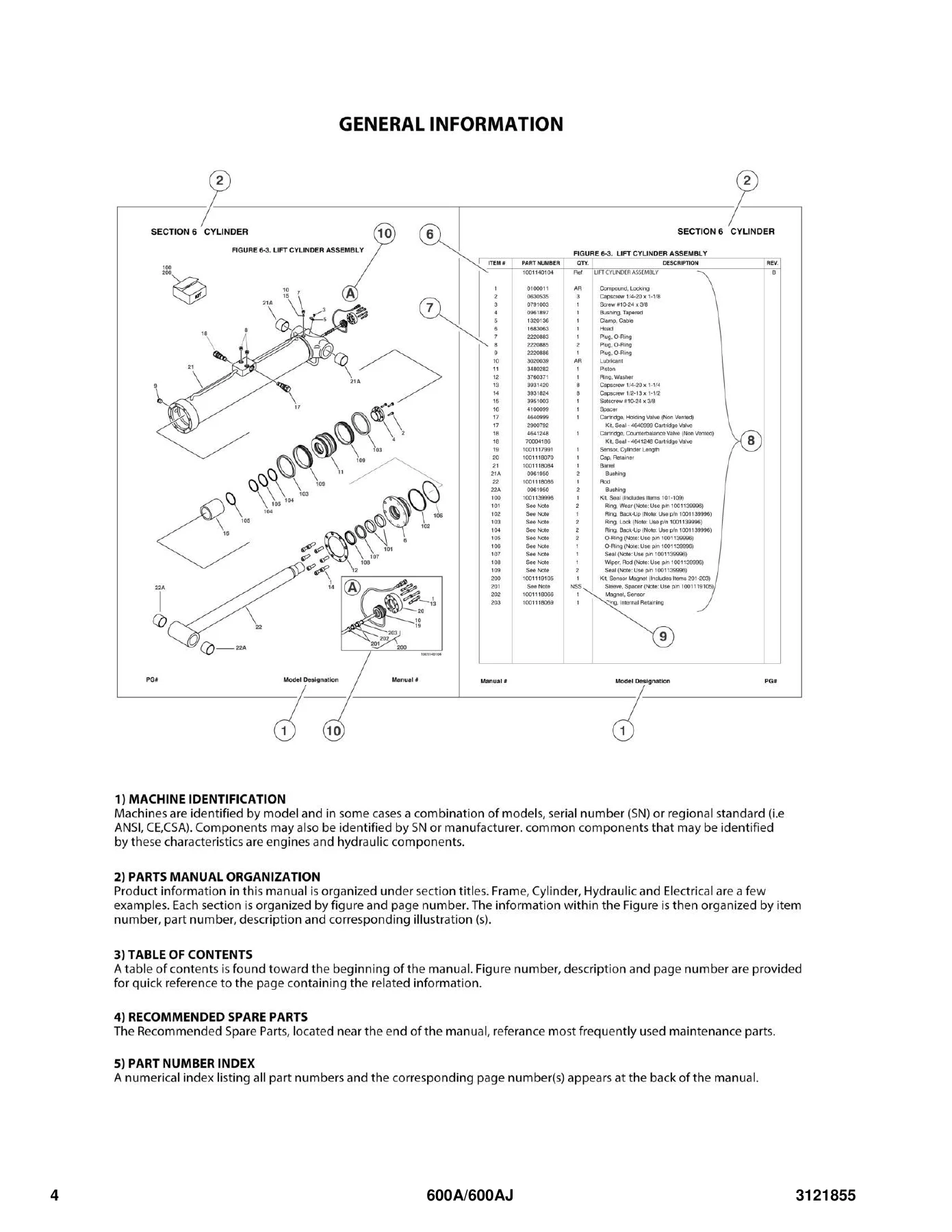
This is the full JLG 600A / 600AJ Illustrated Parts Manual, published under document number 3121855 at Revision AJ and dated January 31, 2019. It is the parts lookup book for the 600A and 600AJ boom lifts, and it is organised the way a parts counter actually works: a figure on one page, a matching parts list on the facing page, and every component identified by item number, part number, quantity, description and revision level. Where a machine changed mid-production, the manual splits the figure and the list by serial number so you order the right component the first time rather than the second.

File Details

  • Manual type: Illustrated Parts Manual
  • Brand: JLG
  • Models covered: 600A, 600AJ
  • Document number: 3121855
  • Revision: AJ (Revised Manual)
  • Revision date: January 31, 2019
  • First issue: June 16, 2003 (Revision A)
  • Language: English
  • Format: PDF
  • Page count: 344 pages

Chapters Covered

  • Section 1 – Frame: 2WD and 4WD front axle and steering installations, 4WS rear steering, tire and wheel drive installations, drive hub assembly, drive hub/brake assembly, drive motor assemblies, drive valves and shields, tow package installation
  • Section 2 – Turntable: control valve installations, main valve block assembly, accessory valve assemblies, swing drive/turntable bearing/turntable lock, swing hub assembly, swing motor assembly, Caterpillar engine installation, generator installation, Deutz engine installation, piston pump assembly, gear pump assembly, tank installations, rotary coupling installations, ground control box assemblies, electrical options, engine tray jack, hoods installations
  • Section 3 – Boom: booms and cylinders installation for 600A and 600AJ, tower boom assemblies, main boom assemblies, rotator assemblies (front entry and side entry platform), valves and switches installation
  • Section 4 – Platform: platform assemblies (front entry and side entry), fall arrest platform components, platform console assembly, controller assemblies for lift/swing and drive/steer, Soft Touch system installation, platform padding
  • Section 5 – Cylinder: axle lockout cylinder, platform level cylinder, level cylinder – platform slave (600A and 600AJ), level cylinder – upright, articulating jib lift cylinder, main boom lift cylinder, tower boom lift cylinder, master cylinder, steer cylinder, main boom and tower boom telescope cylinders, cylinder bellows
  • Section 6 – Hydraulic: drive hydraulic diagrams for 2WD/2WS and 4WD/2WS, oscillating axle hydraulic diagrams, standard hydraulic diagrams for 600A and 600AJ, hydraulic diagram list
  • Section 7 – Electrical: electrical diagram list, electrical schematics for Deutz and Caterpillar machines, harness components installation including platform box harness, boom cables, ground control harness, engine harnesses and valve harnesses
  • Section 8 – Decals: decal installations for both serial-number groups, including safety, capacity, model designation, control and warning decals
  • Section 9 – Recommended Service Parts Stock: standard parts and variable parts lists for field stocking
  • Section 10 – Special Options: special option installations and accessory kits
  • Part Number Index: numerical index of every part number in the manual with the page numbers where it appears

What that structure delivers in practice is a complete, figure-by-figure breakdown of both the 600A and the 600AJ. Assemblies are not left as black boxes — the manual drills into the drive hub, the drive hub/brake unit, the swing hub, the swing motor, the piston pump, the gear pump, the rotary coupling, the main valve block, the accessory valve assemblies, the rotators, the platform console and every controller variant, and lists the internal components of each so that a seal, bearing, gear, carrier, coil, cartridge or plug can be ordered as a separate line item instead of forcing a whole-assembly purchase. Sections 6 and 7 add the hydraulic and electrical side of the same machine, so a component found in a parts figure can be traced to the diagram that shows where it sits in the circuit.

Serial Number Coverage You Can Actually Use

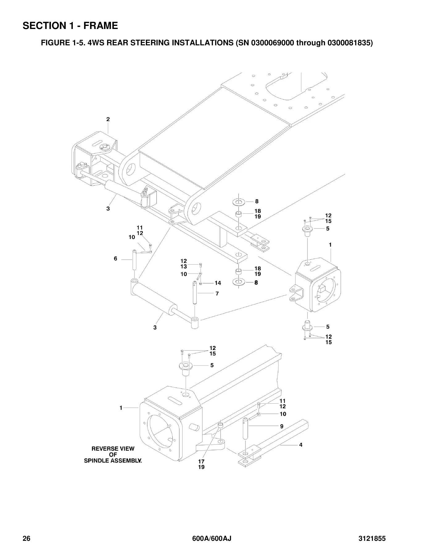
A large share of the figures in this manual are duplicated for two production groups: machines built from serial number 0300069000 through 0300081835, and machines built from 0300081836 through 0300087000. Front axle and steering, rear steering, drive hub and drive hub/brake, drive motor, drive valves, tow package, axle lockout cylinder, rotary coupling, control valves, ground control box, hydraulic diagrams, electrical schematics and decal installations all carry separate figures or separate line items for the two ranges. Later revisions within the second group are split again — for example certain engine, pump, hose and generator part numbers are called out by narrower serial breaks such as 0300084828, 0300084829, 0300086894 and 0300086999. Knowing the machine’s serial number before opening the manual is what makes the part number correct on the first order.

Engines and Major Assemblies Referenced

Engine installations are covered for the Caterpillar engine and for the Deutz F4M1011F diesel, each with its own installation figure and component listing. The manual also covers the auxiliary pump assembly used on the control valve installation, the Sunstrand drive motor assemblies for 2WD and the Rexroth drive motor assembly for 4WD, the original equipment and service replacement drive motor assemblies, the swing motor, the piston pump in both original equipment and service replacement form, the gear pump, and the manual descent, counterbalance, brake, flow divider and shuttle valve assemblies. Rotator assemblies appear separately for front entry and side entry platforms, and the 600AJ-specific articulating jib and Extend-A-Reach lift cylinders get their own figures.

Ordering the Right Part

The manual follows a consistent convention that removes most of the guesswork. Item numbers in the parts list match the callouts on the illustration. Missing item numbers simply mean that callout is not used on that page. Where a component is shown for reference only, the quantity column reads Ref; where a part is not available separately, it reads NSS (Not Sold Separately) or NLA (No Longer Available). Indented descriptions sit underneath the assembly they belong to, so a sub-component is tied to its parent. Revision letters in the REV column flag which generation of the design a line item belongs to, which matters on a machine that was built over more than fifteen years of production.

Why This Manual Earns Its Place in the Workshop

Parts lookups on a boom lift go wrong in one of two ways: ordering a component for the wrong serial number group, or ordering an assembly when a single seal, coil, cartridge or bearing was all that was needed. This manual is built to prevent both. Every figure is tied to a serial-number range, and every assembly is exploded far enough to expose the serviceable internal parts — seals, o-rings, back-up rings, wear rings, wipers, bearings, gears, carriers, pistons, cartridges, coils, plugs and fasteners — with the kit part numbers listed alongside where a kit is the correct purchase. The Recommended Service Parts Stock section at the back is effectively a pre-built emergency stock list for the 600A and 600AJ, separating standard parts from variable parts so a shop knows what to keep on the shelf.

Complete PDF Bookmark Tree

Complete Bookmarks

The complete bookmarks in the “JLG 600A & 600AJ Illustrated Parts Manual 3121855 Rev AJ – 2019 PDF” are as follows:

SECTION 1 – FRAMEp. 9
FIGURE 1-1. 2WD FRONT AXLE AND STEERING INSTALLATIONS (SN 0300069000 through 0300081835)p. 10
FIGURE 1-2. 2WD FRONT AXLE AND STEERING INSTALLATIONS (SN 0300081836 through 0300087000)p. 14
FIGURE 1-3. 4WD FRONT AXLE AND STEERING INSTALLATIONS (SN 0300069000 through 0300081835)p. 18
FIGURE 1-4. 4WD FRONT AXLE AND STEERING INSTALLATIONS (SN 0300081836 through 0300087000)p. 22
FIGURE 1-5. 4WS REAR STEERING INSTALLATIONS (SN 0300069000 through 0300081835)p. 26
FIGURE 1-6. 4WS REAR STEERING INSTALLATIONS (SN 0300081836 through 0300087000)p. 28
FIGURE 1-7. TIRE AND WHEEL DRIVE INSTALLATIONSp. 30
FIGURE 1-8. DRIVE HUB ASSEMBLY (SN 0300069000 through 0300081835)p. 34
FIGURE 1-9. DRIVE HUB/BRAKE ASSEMBLY (SN 0300081836 through 0300087000)p. 36
FIGURE 1-10. DRIVE MOTOR ASSEMBLY (2WD MACHINES) (SN 0300069000 through 0300071019)p. 40
FIGURE 1-11. DRIVE MOTOR ASSEMBLY (2WD MACHINES) (SN 0300071020 through 0300081836)p. 42
FIGURE 1-12. DRIVE MOTOR ASSEMBLY (4WD MACHINES) (SN 0300069000 through 0300081835)p. 44
FIGURE 1-13. DRIVE MOTOR ASSEMBLY (2WD & 4WD MACHINES) (ORIGINAL EQUIPMENT) (SN 0300081836 through 0300087000)p. 46
FIGURE 1-14. DRIVE MOTOR ASSEMBLY (2WD & 4WD MACHINES) (SERVICE REPLACEMENT)p. 48
FIGURE 1-15. DRIVE VALVES AND SHIELDS INSTALLATION (FRAME MOUNTED) (SN 0300069000 through 0300081835)p. 50
FIGURE 1-16. DRIVE VALVES AND SHIELDS INSTALLATION (FRAME MOUNTED) (SN 0300081836 through 0300087000)p. 52
FIGURE 1-17. TOW PACKAGE INSTALLATION (OPTIONAL) (SN 0300069000 through 0300081835)p. 56
FIGURE 1-18. TOW PACKAGE INSTALLATION (OPTIONAL) (SN 0300081836 through 0300087000)p. 58
SECTION 2 – TURNTABLEp. 61
FIGURE 2-1. CONTROL VALVES INSTALLATIONSp. 62
FIGURE 2-2. MAIN VALVE BLOCK ASSEMBLYp. 68
FIGURE 2-3. ACCESSORY VALVE ASSEMBLIESp. 72
FIGURE 2-4. SWING DRIVE, TURNTABLE BEARING AND LOCK INSTALLATIONSp. 74
FIGURE 2-5. SWING HUB ASSEMBLYp. 76
FIGURE 2-6. SWING MOTOR ASSEMBLYp. 78
FIGURE 2-7. CATERPILLAR ENGINE INSTALLATIONp. 80
FIGURE 2-8. GENERATOR INSTALLATION (CATERPILLAR ENGINE MACHINES) (OPTIONAL)p. 88
FIGURE 2-9. DEUTZ ENGINE INSTALLATION (SN 0300069000 through 0300077489)p. 92
FIGURE 2-10. DEUTZ ENGINE INSTALLATION (SN 0300077490 through 0300087000)p. 98
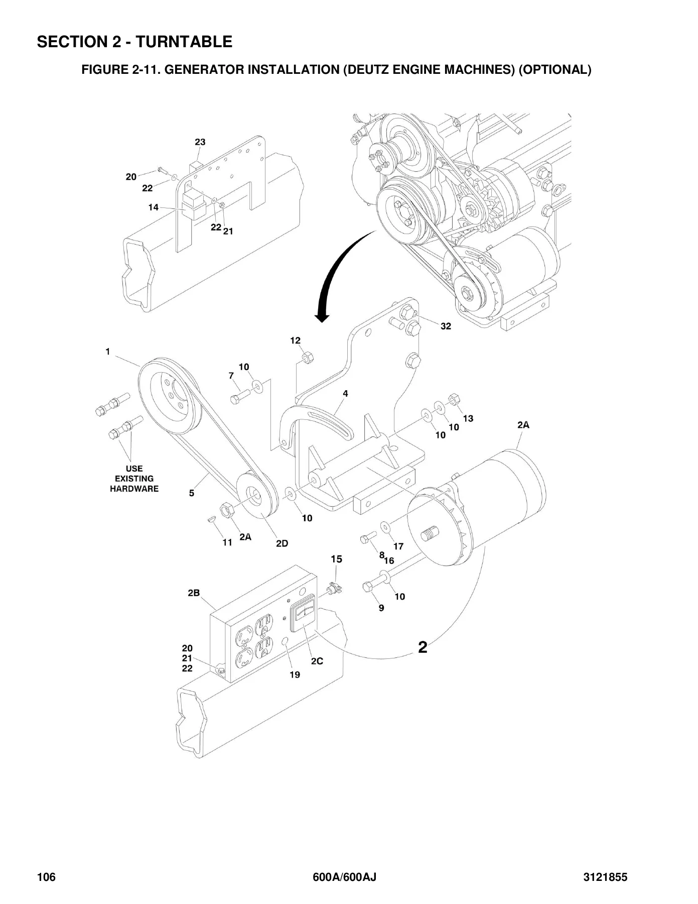
FIGURE 2-11. GENERATOR INSTALLATION (DEUTZ ENGINE MACHINES) (OPTIONAL)p. 106
FIGURE 2-12. PISTON PUMP ASSEMBLY (SN 0300069000 through 0300079887)p. 110
FIGURE 2-13. PISTON PUMP ASSEMBLY (SN 0300079888 through 0300087000)p. 116
FIGURE 2-14. GEAR PUMP ASSEMBLYp. 120
FIGURE 2-15. TANK INSTALLATIONSp. 122
FIGURE 2-16. ROTARY COUPLING INSTALLATIONS (SN 0300069000 through 0300081835)p. 124
FIGURE 2-17. ROTARY COUPLING INSTALLATIONS (SN 0300081836 through 0300087000)p. 126
FIGURE 2-18. GROUND CONTROL BOX ASSEMBLIESp. 130
FIGURE 2-19. ELECTRICAL OPTIONS INSTALLATIONS (TURNTABLE MOUNTED)p. 134
FIGURE 2-20. ENGINE TRAY JACK INSTALLATIONS (OPTIONAL)p. 138
FIGURE 2-21. HOODS INSTALLATIONSp. 140
SECTION 3 – BOOMp. 145
FIGURE 3-1. BOOMS AND CYLINDERS INSTALLATION – 600Ap. 146
FIGURE 3-2. BOOMS AND CYLINDERS INSTALLATION – 600AJp. 150
FIGURE 3-3. TOWER BOOM ASSEMBLIESp. 156
FIGURE 3-4. MAIN BOOM ASSEMBLIESp. 160
FIGURE 3-5. ROTATOR ASSEMBLIES (FRONT ENTRY PLATFORM)p. 164
FIGURE 3-6. ROTATOR ASSEMBLIES (SIDE ENTRY PLATFORM)p. 168
FIGURE 3-7. VALVES AND SWITCHES INSTALLATION (BOOM MOUNTED)p. 170
SECTION 4 – PLATFORMp. 175
FIGURE 4-1. PLATFORM ASSEMBLIES (FRONT ENTRY PLATFORM)p. 176
FIGURE 4-2. PLATFORM ASSEMBLIES – SIDE ENTRYp. 180
FIGURE 4-3. PLATFORM COMPONENTS INSTALLATION (FALL ARREST PLATFORM)p. 184
FIGURE 4-4. PLATFORM CONSOLE ASSEMBLYp. 186
FIGURE 4-5. CONTROLLER ASSEMBLY (LIFT AND SWING)p. 190
FIGURE 4-6. CONTROLLER ASSEMBLY (LIFT AND SWING)p. 192
FIGURE 4-7. CONTROLLER ASSEMBLY (LIFT AND SWING)p. 194
FIGURE 4-8. CONTROLLER ASSEMBLY (DRIVE AND STEER)p. 198
FIGURE 4-9. CONTROLLER ASSEMBLY (DRIVE AND STEER)p. 200
FIGURE 4-10. CONTROLLER ASSEMBLY (DRIVE AND STEER)p. 202
FIGURE 4-11. SOFT TOUCH SYSTEM INSTALLATION (OPTIONAL)p. 204
FIGURE 4-12. PLATFORM PADDING INSTALLATION (SIDE ENTRY PLATFORM) (OPTIONAL)p. 206
SECTION 5 – CYLINDERp. 209
FIGURE 5-1. AXLE LOCKOUT CYLINDER ASSEMBLY (SN 0300069000 through 0300081835)p. 210
FIGURE 5-2. AXLE LOCKOUT CYLINDER ASSEMBLY (SN 0300081836 through 0300087000)p. 212
FIGURE 5-3. PLATFORM LEVEL CYLINDER ASSEMBLY (ORIGINAL EQUIPMENT)p. 214
FIGURE 5-4. LEVEL CYLINDER ASSEMBLY – PLATFORM SLAVE (600A) (SERVICE REPLACEMENT)p. 218
FIGURE 5-5. LEVEL CYLINDER ASSEMBLY – PLATFORM SLAVE (600AJ) (SERVICE REPLACEMENT)p. 220
FIGURE 5-6. LEVEL CYLINDER ASSEMBLY – UPRIGHTp. 222
FIGURE 5-7. LEVEL CYLINDER ASSEMBLY – UPRIGHT (SERVICE REPLACEMENT)p. 224
FIGURE 5-8. LIFT CYLINDER ASSEMBLY – ARTICULATING JIB (600AJ)p. 226
FIGURE 5-9. LIFT CYLINDER ASSEMBLY – ARTICULATING JIB (600AJ) (SERVICE REPLACEMENT)p. 228
FIGURE 5-10. LIFT CYLINDER ASSEMBLY – ARTICULATING JIB (600AJ) (SERVICE REPLACEMENT)p. 230
FIGURE 5-11. LIFT CYLINDER ASSEMBLY – MAIN BOOM (ORIGINAL EQUIPMENT)p. 232
FIGURE 5-12. LIFT CYLINDER ASSEMBLY – MAIN BOOM (SERVICE REPLACEMENT)p. 234
FIGURE 5-13. LIFT CYLINDER ASSEMBLY – TOWER BOOM (ORIGINAL EQUIPMENT)p. 236
FIGURE 5-14. LIFT CYLINDER ASSEMBLY – TOWER BOOM (SERVICE REPLACEMENT)p. 238
FIGURE 5-15. MASTER CYLINDER ASSEMBLY (ORIGINAL EQUIPMENT)p. 240
FIGURE 5-16. MASTER CYLINDER ASSEMBLY – 600A (SERVICE REPLACEMENT)p. 244
FIGURE 5-17. MASTER CYLINDER ASSEMBLY – 600AJ (SERVICE REPLACEMENT)p. 246
FIGURE 5-18. STEER CYLINDER ASSEMBLYp. 248
FIGURE 5-19. TELESCOPE CYLINDER ASSEMBLY – MAIN BOOM (ORIGINAL EQUIPMENT)p. 250
FIGURE 5-20. TELESCOPE CYLINDER ASSEMBLY – MAIN BOOM (600A) (SERVICE REPLACEMENT)p. 252
FIGURE 5-21. TELESCOPE CYLINDER ASSEMBLY – MAIN BOOM (600AJ) (SERVICE REPLACEMENT)p. 254
FIGURE 5-22. TELESCOPE CYLINDER ASSEMBLY – TOWER BOOM (ORIGINAL EQUIPMENT)p. 256
FIGURE 5-23. TELESCOPE CYLINDER ASSEMBLY – TOWER BOOM (SERVICE REPLACEMENT)p. 258
FIGURE 5-24. CYLINDER BELLOWS INSTALLATION (OPTIONAL)p. 260
SECTION 6 – HYDRAULICp. 263
FIGURE 6-1. DRIVE HYDRAULIC DIAGRAM – 2WD/2WS (SN 0300069000 through 0300081835)p. 264
FIGURE 6-2. DRIVE HYDRAULIC DIAGRAM – 2WD/2WS (SN 0300081836 through 0300087000)p. 266
FIGURE 6-3. DRIVE HYDRAULIC DIAGRAM – 4WD/2WS (SN 0300069000 through 0300081835)p. 268
FIGURE 6-4. DRIVE HYDRAULIC DIAGRAM – 4WD/2WS (SN 0300081836 through 0300087000)p. 272
FIGURE 6-5. HYDRAULIC DIAGRAM – OSCILLATING AXLE (SN 0300069000 through 0300081835)p. 274
FIGURE 6-6. HYDRAULIC DIAGRAM – OSCILLATING AXLE (SN 0300081836 through 0300087000)p. 276
FIGURE 6-7. HYDRAULIC DIAGRAM – STANDARD (SN 0300069000 through 0300081835)p. 278
FIGURE 6-8. HYDRAULIC DIAGRAM – STANDARD (SN 0300081836 through 0300087000)p. 282
FIGURE 6-9. HYDRAULIC DIAGRAM LISTp. 286
SECTION 7 – ELECTRICALp. 289
FIGURE 7-1. ELECTRICAL DIAGRAM LISTp. 290
FIGURE 7-2. ELECTRICAL SCHEMATIC (DEUTZ AND ALL CATERPILLAR) (SN 0300069000 through 0300084711)p. 292
FIGURE 7-3. ELECTRICAL SCHEMATIC – DEUTZ ENGINE (SN 0300084827 through 0300087000)p. 298
FIGURE 7-4. HARNESS COMPONENTS INSTALLATIONp. 302
SECTION 8 – DECALSp. 313
FIGURE 8-1. DECAL INSTALLATION (SN 0300069000 through 0300086149)p. 314
FIGURE 8-2. DECAL INSTALLATION (SN 0300086150 through 0300087000)p. 318
SECTION 9 – RECOMMENDED SERVICE PARTS STOCKp. 321
FIGURE 9-1. MODEL 600A/600AJ STANDARD PARTSp. 322
FIGURE 9-2. MODEL 600A/600AJ VARIABLE PARTSp. 324
SECTION 10 – SPECIAL OPTIONSp. 325
FIGURE 10-1. SPECIAL OPTIONSp. 326
PART NUMBER INDEXp. 331


IMAGES PREVIEW

JLG 600A & 600AJ Illustrated Parts Manual 3121855 Rev AJ – 2019 PDF — PDF page 4 preview
JLG 600A & 600AJ Illustrated Parts Manual 3121855 Rev AJ – 2019 PDF — PDF page 26 preview
JLG 600A & 600AJ Illustrated Parts Manual 3121855 Rev AJ – 2019 PDF — PDF page 106 preview

Instant PDF Delivery

The JLG 600A/600AJ Illustrated Parts Manual 3121855 Rev AJ is supplied as a PDF and is available to download immediately after payment, with no shipping and nothing to wait for. Keep it on the shop computer, load it onto a tablet at the machine, or print the figures and parts lists you need for the job at hand — the pages are laid out so a printed figure and its parts list stay usable together. Whether you are running a single 600A, maintaining a mixed fleet of 600A and 600AJ units, or rebuilding a drive hub, swing drive, rotator or hydraulic cylinder, this is the reference that turns a description of a broken part into the exact part number JLG built the machine with.
Reviews

There are no reviews yet.

Be the first to review “JLG 600A & 600AJ Illustrated Parts Manual 3121855 Rev AJ – 2019 PDF”

What Our Customers Say

★★★★★ Live reviews from customers
Loading customer reviews...
0
    0
    Your Cart
    Your cart is emptyReturn to Shop
    🛒
    Recently Purchased
    🕒 verified order