
★ TRUSTED BY 321,897+ PROFESSIONALS WORLDWIDE
🏢
Trusted Business
Verified & Licensed
🛡️
Virus Free Files
100% Safe Downloads
🔒
Secure Payment
SSL Protected
Instant Delivery
Available Immediately
Sale!

JLG 800AJ PVC 2107 Service and Maintenance Manual 31219065 Rev A – 2021 PDF

Original price was: $49.95.Current price is: $29.95.

Complete 656-page service and maintenance reference for the JLG 800AJ, PVC 2107, document 31219065 Rev A dated July 12, 2021. Covers specifications, inspections, chassis and turntable service, boom and platform systems, hydraulics, JLG controls, diagnostics, and electrical/hydraulic schematics.

Instant PDF Download
Available immediately
💾
Save to Your Device
Download & keep forever
🛡️
Antivirus Scanned
100% virus-free
🌍
Trusted Worldwide
175,000+ customers

Description

JLG 800AJ PVC 2107 Service and Maintenance Manual 31219065 Rev A – 2021 PDF

This JLG 800AJ PVC 2107 Service and Maintenance Manual 31219065 Rev A – 2021 PDF is a detailed technical reference for servicing and maintaining the JLG 800AJ. The manual combines machine specifications and scheduled maintenance information with extensive component repair procedures, hydraulic service data, control-system diagnostics, and electrical and hydraulic schematics. It is especially useful when work goes beyond routine checks and requires procedures for major chassis, turntable, boom, platform, hydraulic, drive, swing, engine, or control-system components.

File Details

  • Manual type: Service and Maintenance Manual
  • Brand: JLG
  • Model: 800AJ
  • Configuration: PVC 2107
  • Document number: 31219065
  • Revision: Rev A
  • Date: July 12, 2021
  • Language: English
  • Pages: 656
  • File format: PDF

Service Depth for the JLG 800AJ

The manual opens with maintenance safety precautions and then moves into machine data used during inspection, repair, adjustment, and reassembly. Specifications include operating data, capacities, tires, engine data, drive and swing component information, torque requirements, hydraulic oil information, major component weights, lubrication information, threadlocking compounds, and SAE and metric fastener torque charts. The machine specification section includes details such as unrestricted platform capacity, travel speed, gradeability, dimensions, approximate machine weight, fuel and hydraulic capacities, and component weights.

Engine coverage is substantial because the 800AJ can be represented in this manual with several engine configurations. Dedicated information is included for the Deutz D2011L04, Deutz TD2.9L4, Deutz TD2.9L4 China III, Deutz TD2.9L4 Stage V, and Ford 2.5L DF, MSG-425. The manual includes engine installation illustrations, maintenance procedures, fuel and oil service information, engine-related fault references, and, where applicable, emissions and diesel particulate filter material.

Inspection, Maintenance and Repair Information

For scheduled upkeep, the JLG 800AJ service manual provides pre-start, pre-delivery, frequent, annual, and preventive maintenance guidance, together with lubrication intervals and service points. It also explains workshop practices for cleanliness, bearing and gasket handling, component removal and installation, bolt use and torque application, hydraulic lines, electrical wiring, batteries, and lubrication. Hydraulic cylinder drift is treated as a diagnostic subject with leakage and thermal-drift considerations rather than simply as a replacement instruction.

Chassis and turntable coverage reaches into component-level service. Procedures and illustrations address tires and wheels, axle lockout, drive and steer systems, drive hubs, brakes, drive motors, swing drive and swing motor work, swing bearing inspection and replacement, rotary coupling, generator service, auxiliary power, engine installations, counterweight information, and related troubleshooting. Many assemblies include disassembly, inspection, repair, assembly, testing, and start-up sequences.

Boom and platform work is similarly detailed. The manual covers platform load control, the platform assembly, rotator and platform level cylinder, main and tower boom systems, powertracks, upright components, the Upright Monitoring System, UMS diagnostic trouble codes, articulating jib and jib lift cylinder, hose replacement, limit-switch adjustment, boom valve adjustment, rotator overhaul, foot-switch adjustment, SkyGuard, and bolt-on external fall arrest equipment. This gives technicians a single reference for both mechanical assemblies and the sensing/control functions associated with boom operation.

Hydraulic, Control and Electrical Diagnostics

A large hydraulic section explains connection assembly and torque specifications for multiple fitting types, cylinder service, cylinder removal and installation, pressure-setting procedures, hydraulic component start-up, drive pump pre-fill, function pump and drive pump work, holding-valve checks, and hydraulic schematics. Cylinder coverage includes axle lockout, platform level, main boom lift, tower lift, upright level, jib lift, master, steer, main boom telescope, and tower boom telescope cylinders. Exploded drawings and assembly illustrations support seal, bushing, piston, rod, and related repair work.

The JLG Control System section covers analyzer-kit use, machine configuration programming, personality settings, function speeds, CANbus communications, the LSS system, MSSO reset procedures, and diagnostic trouble codes. This is followed by basic electrical service information covering multimeter use, electrical connector servicing, AMP and Deutsch connectors, telematics gateway information, harness illustrations, and a multi-sheet electrical schematic set. Together with the hydraulic schematic section, these pages are valuable for tracing faults that involve both hydraulic actuation and electronic control.

Complete PDF Bookmark Tree

Complete Bookmarks

The complete bookmarks in the “JLG 800AJ PVC 2107 Service and Maintenance Manual 31219065 Rev A – 2021 PDF” are as follows:

31219065_A_800AJ_JLG_Service_Englishp. 1
Section A. Introduction – Maintenance Safety Precautionsp. 3
A Generalp. 3
B Hydraulic System Safetyp. 3
C Maintenancep. 3
Table of Contentsp. 5
List of Figuresp. 13
List of Tablesp. 20
Section 1. Specificationsp. 23
1.1 Operating Specificationsp. 23
Machine Specificationsp. 23
1.2 Capacitiesp. 23
1.3 Tiresp. 23
1.4 Engine Datap. 23
1.5 Component Datap. 24
Drive Systemp. 24
Swing Systemp. 24
Auxiliary Power Pumpp. 24
1.6 Torque Requirementsp. 25
1.7 Hydraulic Oilp. 25
1.8 Major Component Weightsp. 27
Critical Stability Weightsp. 27
1.9 Operator Maintenancep. 29
1.10 Threadlocking Compoundp. 34
1.11 Torque Chartsp. 35
SAE Fastener Torque Chartp. 35
Metric Fastener Torque Chartp. 41
Section 2. Generalp. 45
2.1 Machine Preparation, Inspection, and Maintenancep. 45
Generalp. 45
Preparation, Inspection, and Maintenancep. 45
Pre-Start Inspectionp. 45
Pre-Delivery Inspection and Frequent Inspectionp. 45
Annual Machine Inspectionp. 45
Preventative Maintenancep. 45
2.2 Service and Guidelinesp. 46
Generalp. 46
Safety and Workmanshipp. 46
Cleanlinessp. 46
Components Removal and Installationp. 46
Component Disassembly and Reassemblyp. 46
Pressure-Fit Partsp. 46
Bearingsp. 47
Gasketsp. 47
Bolt Usage and Torque Applicationp. 47
Hydraulic Lines and Electrical Wiringp. 47
Hydraulic Systemp. 47
Lubricationp. 47
Batteryp. 47
Lubrication and Servicingp. 47
2.3 Lubrication and Informationp. 47
Hydraulic Systemp. 47
Hydraulic Oilp. 48
Changing Hydraulic Oilp. 48
Lubrication Specificationsp. 48
2.4 Cylinder Drift Testp. 49
Theoryp. 49
Cylinder Leakage Testp. 49
Cylinder Thermal Driftp. 49
2.5 Pins and Composite Bearing Repair Guidelinesp. 50
2.6 Welding on JLG Equipmentp. 50
DO the Following When Welding on JLG Equipmentp. 50
DO NOT Do the Following When Welding on JLG Equipmentp. 50
Section 3. Chassis & Turntablep. 57
3.1 Tires & Wheelsp. 57
Tire Damagep. 57
Tire Replacementp. 57
Wheel Replacementp. 57
Wheel Installationp. 57
3.2 Lockout Cylinder Bleedingp. 58
3.3 Oscillating Axle Lockout Testp. 61
3.4 Chassis Tilt Indicator Systemp. 64
3.5 Drive Orientation Systemp. 64
3.6 Transport Position Sensing Systemp. 64
3.7 Beyond Transport – Drive Speed Cutback Systemp. 64
3.8 Drive/Steer – Boom Function Interlock Systemp. 64
3.9 Oscillating Axle Systemp. 65
3.10 Drive Systemp. 65
3.11 Drive Hub (Torque)p. 66
Disassemblyp. 66
Cleaning and Inspectionp. 66
Repairp. 66
Assemblyp. 68
3.12 Drive Brakep. 74
Disassemblyp. 74
Inspectionp. 74
Assemblyp. 74
3.13 Drive Motorp. 76
Descriptionp. 76
Shaft Seal Replacementp. 76
Loop Flushing Valvep. 77
Troubleshootingp. 78
Disassemblyp. 79
Inspectionp. 83
Assemblyp. 85
Initial Start-up Proceduresp. 90
3.14 Swing Drivep. 92
Roll, Leak and Brake Testingp. 92
Tightening and Torquing Boltsp. 93
Motor Control Valve Disassemblyp. 94
Motor and Brake Disassemblyp. 95
Main Drive Disassemblyp. 96
Hub-Shaft Disassemblyp. 97
Carrier Disassemblyp. 98
Hub-Shaft Assemblyp. 99
Carrier Assemblyp. 99
Main Drive Assemblyp. 100
Motor and Brake Assemblyp. 101
Motor Control Valve Assemblyp. 102
3.15 Swing Motorp. 109
Disassembly and Inspectionp. 109
Assemblyp. 116
One Piece Stator Constructionp. 124
3.16 Swing Hub Installationp. 125
Procedure for Setting Swing Gear Backlashp. 125
Swing Drive Lubricationp. 126
3.17 Swing Hub Removalp. 126
3.18 Swing Bearingp. 127
Turntable Bearing Mounting Bolt Condition Checkp. 127
Wear Tolerancep. 130
Swing Bearing Replacementp. 130
Swing Bearing Torque Valuesp. 131
3.19 Tilt Indicator Systemp. 133
3.20 Spark Arrester Cleaning Instructionsp. 133
3.21 Rotary Couplingp. 134
3.22 Generatorp. 140
Maintenance Schedulep. 140
Overload Protectionp. 140
Inspecting Brushes, Replacing Brushes, and Cleaning Slip Ringsp. 140
Troubleshootingp. 142
Generator Disassembly and Assemblyp. 143
Lead Connection List for Generatorp. 150
Generator Pulleyp. 151
3.23 Auxiliary Power Systemp. 159
3.24 Deutz TD2.9L4 Enginep. 160
Check Oil Levelp. 170
Change Engine Oilp. 170
Change Oil Filterp. 171
Change Fuel Filtersp. 171
Replacing the Fuel Pre-Filterp. 172
Water in Fuel Sensing System (Optional)p. 172
Draining Waterp. 172
Auxiliary Fuel Filterp. 173
3.25 Deutz TD2.9L4 China III Enginep. 174
Check Oil Levelp. 181
Change Engine Oilp. 181
Change Oil Filterp. 182
Change Fuel Filtersp. 182
Replacing the Fuel Pre-Filterp. 183
Water in Fuel Sensing System (Optional)p. 183
Draining Waterp. 183
Auxiliary Fuel Filterp. 184
3.26 Deutz Engine – D2011L04p. 185
Glow Plugsp. 189
Check Oil Levelp. 189
Replacing Engine Oilp. 190
Replacing the Oil Filterp. 191
Replacing the Primary Fuel Filterp. 191
Deutz EMR2p. 192
3.27 Ford Enginep. 254
3.28 Deutz Engine TD2.9L4 (Stage V)p. 266
Check Oil Levelp. 273
Change Engine Oilp. 273
Change Oil Filterp. 274
Change Fuel Filtersp. 274
Replacing the Fuel Pre-Filterp. 275
Water in Fuel Sensing Systemp. 275
Draining Waterp. 276
Deutz EMR5p. 277
3.29 HRC Engine Emission Characteristicsp. 304
Terminology for Removing Sootp. 304
3.30 Diesel Particulate Filter (If Equipped)p. 305
Standstill Cleaningp. 306
Maintenance Standstill Cleaning Initiation Methodsp. 307
Canceling Maintenance Standstillp. 307
Unsuccessful Cleaning Eventp. 307
DPF Filter Replacement due to Ash Loadp. 307
Ash Loadp. 310
3.31 Dual Fuel Systemp. 311
Changing from Gasoline to LP Gasp. 311
Changing from LP Gas to Gasolinep. 311
3.32 Counterweightp. 312
Section 4. Boom & Platformp. 313
4.1 Platform Load Control Systemp. 313
4.2 Machine Safety System Override (MSSO) (CE only)p. 313
4.3 Platformp. 313
Platform Valve Removalp. 313
Platform Valve Installationp. 314
Platform Support Removalp. 314
Support Installationp. 315
4.4 Rotator and Platform Level Cylinderp. 318
Removalp. 318
Installationp. 318
4.5 Boom Systemp. 319
Platform Control Enable Systemp. 319
Function Speed Control Systemp. 319
Platformp. 319
Main Lift End Stroke Dampening Systemp. 319
QuikStick Lift Systemp. 319
Tower Boom Sequence Valve Systemp. 319
Upright Level Systemp. 319
Ground Control Keyswitch Systemp. 319
4.6 Main Boom Powertrackp. 321
Removalp. 321
4.7 Powertrack Maintenancep. 327
Flat Bar Removalp. 327
Round Bar/Poly Bar Removalp. 327
Removing and Installing Linksp. 328
Installing a New Flat Barp. 331
Installing a New Round Bar/Poly Rollerp. 332
Replacing a Fixed End Bracketp. 332
Replacing a Moving End Bracketp. 333
Replacing a One Piece Bracketp. 333
4.8 Boom Cleanliness Guidelinesp. 334
4.9 Main Boom Assemblyp. 337
Removalp. 337
Disassemblyp. 338
Inspectionp. 338
Assemblyp. 338
Installationp. 339
4.10 Uprightp. 340
Removalp. 340
Installationp. 341
4.11 Tower Boom Assemblyp. 343
Removalp. 343
Inspectionp. 343
Assemblyp. 344
Installationp. 344
Tower Out of Syncp. 345
4.12 Upright Monitoring System (UMS)p. 347
Re-Synchronizing Uprightp. 347
Calibrationp. 349
Calibration Faultsp. 353
Function Checkp. 354
Service Mode/Tower Boom Retrievalp. 355
4.13 UMS Troubleshooting and Diagnostic Trouble Codes (DTC)p. 359
Backward Stability Concern DTC (2532)p. 359
Forward Stability Concern DTC (2530)p. 359
Out of Usable Range DTC (2531)p. 359
UMS Sensor Not Calibrated DTC (816)p. 359
UMS Sensor Faulted DTC (817)p. 359
Calibration Faultsp. 359
4.14 Articulating Jib and Jib Lift Cylinderp. 360
Removalp. 360
Disassemblyp. 360
Inspectionp. 360
Assemblyp. 361
Installationp. 361
4.15 Sequence for Hose Replacement in the Tower Boomp. 362
4.16 Limit Switches Adjustmentp. 362
Main Boom Horizontal Limit Switchp. 362
Tower Boom Horizontal Limit Switchp. 362
4.17 Boom Valve Adjustmentp. 367
Tower Boomp. 367
Main Boomp. 367
4.18 Rotator Assemblyp. 368
Theory of Operationp. 368
Required Toolsp. 368
Disassemblyp. 371
Inspectionp. 375
Assemblyp. 375
Installing Counterbalance Valvep. 381
Greasing Thrust Washersp. 382
Testing the Actuatorp. 382
Installation and Bleedingp. 383
4.19 Foot Switch Adjustmentp. 383
Troubleshootingp. 384
4.20 Skyguard®p. 385
Operationp. 385
Function Testp. 385
Diagnostics & Troubleshootingp. 386
4.21 Bolt-On External Fall Arrestp. 387
Inspection Before Usep. 387
Installationp. 387
Section 5. Basic Hydraulics Information & Schematicsp. 391
5.1 Lubricating O-Rings in the Hydraulic Systemp. 391
Cup and Brushp. 391
Dip Methodp. 392
Spray Methodp. 392
Brush-on Methodp. 392
5.2 Hydraulic Connection Assembly and Torque Specificationp. 393
Tapered Thread Typesp. 393
Straight Thread Types, Tube and Hose Connectionsp. 393
Straight Thread Types, Port Connectionsp. 394
Flange Connection Typesp. 394
Tightening Methodsp. 394
Assembly and Torque Specificationsp. 395
Assembly Instructions for American Standard Pipe Thread Tapered (NPTF) Connections.p. 396
Assembly Instructions for British Standard Pipe Thread Tapered (BSPT) Connectionsp. 397
Assembly Instructions for 37° (JIC) Flare Fittingsp. 398
Assembly Instructions for 45° SAE Flare Fittingsp. 402
Assembly Instructions for O-Ring Face Seal (ORFS) Fittingsp. 404
Assembly Instructions for DIN 24° Flare Bite Type Fittings (MBTL and MBTS)p. 406
Assembly Instructions for Bulkhead (BH) Fittingsp. 408
Assembly Instructions for O-Ring Boss (ORB) Fittingsp. 412
Assembly Instructions for Adjustable Port End Metric (MFF) Fittingsp. 420
Assembly Instructions for Metric ISO 6149 (MPP) Port Assembly Stud Endsp. 428
Assembly Instructions for Adjustable Port End (BSPP) Fittingsp. 430
Assembly Instructions for Flange Connections: (FL61 and FL62)p. 438
Double Wrench Methodp. 441
FFWR and TFFT Methodsp. 442
Adjustable Stud End Assemblyp. 442
O-ring Installation (Replacement)p. 443
5.3 Hydraulic Cylindersp. 444
Axle Lockout Cylinderp. 444
Platform Level Cylinderp. 446
Main Boom Lift, Tower Lift and Upright Level Cylinderp. 452
Disassemblyp. 452
Assemblyp. 455
Main Boom Lift Cylinderp. 457
Tower Boom Lift Cylinderp. 458
Jib Lift Cylinderp. 460
Master Cylinderp. 466
Steer Cylinderp. 472
Cleaning and Inspectionp. 474
Main Boom Telescope Cylinderp. 477
Tower Boom Telescope Cylinderp. 483
5.4 Cylinder Removal and Installationp. 489
Removalp. 489
Main Boom Telescope Cylinder Installationp. 491
Main Lift Cylinder Removalp. 492
Main Lift Cylinder Installationp. 493
Upright Level Cylinder Removalp. 494
Upright Level Cylinder Installationp. 495
Tower Boom Lift Cylinder Removalp. 495
Tower Boom Lift Cylinder Installationp. 496
Tower Telescope Cylinder Removalp. 497
Tower Telescope Cylinder Installationp. 497
Master Cylinder Removalp. 498
Master Cylinder Installationp. 498
5.5 Hydraulic Pump W/Hayes Pump Drive Coupling Lubricationp. 499
5.6 Pressure Setting Proceduresp. 499
Set Up the Function Pumpp. 499
Adjustments Made at the Main Valve Blockp. 509
Adjustments Made at the Platform Valve Blockp. 509
5.7 Hydraulic Component Start-Up Procedures and Recommendationsp. 510
5.8 Hydraulic Drive Pump Pre-fill Procedurep. 512
5.9 Function Pumpp. 513
Removalp. 513
Installationp. 513
Initial Start-up Proceduresp. 515
Troubleshootingp. 516
Shaft Seal Replacementp. 520
Control Assemblyp. 520
Plug and Fitting Sizes and Torquesp. 522
5.10 Drive Pumpp. 523
Removalp. 523
Installationp. 523
Servo Controlled Piston Pumpp. 524
Charge Pump Adapter Assemblyp. 527
Manual Servo Control Basic Assemblyp. 528
Manual Servo Control Assembly Optionsp. 529
Rotating Kit Assemblyp. 531
Fault- logic Troubleshootingp. 532
Start-up Procedurep. 537
5.11 Upright Level System Holding Valve Checksp. 538
5.12 Hydraulic Schematicsp. 540
Section 6. JLG Control Systemp. 543
6.1 JLG Control System Analyzer Kit Instructionsp. 543
Introductionp. 543
To Connect the JLG Control System Analyzerp. 544
Using the Analyzerp. 544
Changing the Access Level of the Hand Held Analyzerp. 545
Adjusting Parameters Using the Hand Held Analyzerp. 546
Machine Setupp. 547
Level Vehicle Descriptionp. 547
6.2 Machine Configuration Programming Informationp. 551
6.3 Machine Personality Settings and Function Speedsp. 559
6.4 Machine Orientation When Setting Function Speedsp. 562
Test Notesp. 562
6.5 CANbus Communicationsp. 563
Analyzer Diagnostics Menu Structurep. 579
6.6 LSS Systemp. 582
Diagnostic Menup. 583
Calibration Procedurep. 584
Testing & Evaluationp. 589
Troubleshootingp. 590
6.7 Resetting the MSSO Systemp. 591
6.8 Diagnostic Trouble Codes (DTC)p. 592
Section 7. Basic Electrical Information & Schematicsp. 609
7.1 Generalp. 609
7.2 Multimeter Basicsp. 609
Groundingp. 609
Backprobingp. 609
Min/Maxp. 609
Polarityp. 609
Scalep. 609
Voltage Measurementp. 609
Resistance Measurementp. 610
Continuity Measurementp. 610
Current Measurementp. 611
7.3 Applying Silicone Dielectric Compound to Electrical Connectionsp. 611
Installation of Dielectric Greasep. 612
AMP Mate-N-Lokp. 612
AMP Fastonp. 612
AMP Micro-Fitp. 612
AMP Mini Fit Jrp. 612
Mini Fit Srp. 613
DIN Connectorsp. 613
Exceptionsp. 613
Enclosuresp. 613
Carling Switch Connectorsp. 613
7.4 AMP Connectorp. 614
Applying Silicone Dielectric Compound to AMP Connectorsp. 614
Assemblyp. 614
Disassemblyp. 616
Wedge Lockp. 616
Service – Voltage Readingp. 616
7.5 Deutsch Connectorsp. 618
DT/DTP Series Assemblyp. 618
DT/DTP Series Disassemblyp. 618
HD30/HDP20 Series Assemblyp. 619
HD30/HDP20 Series Disassemblyp. 619
7.6 Telematics Gatewayp. 620
Telematics-Ready (TCU) Plugp. 620
7.7 Electrical Schematicsp. 642

Chapters Covered

  • Section A – Introduction – Maintenance Safety Precautions
    • General
    • Hydraulic System Safety
    • Maintenance
  • Section 1 – Specifications
    • Operating Specifications and Machine Specifications
    • Capacities, Tires and Engine Data
    • Component Data: Drive System, Swing System and Auxiliary Power Pump
    • Torque Requirements and Hydraulic Oil
    • Major Component Weights and Critical Stability Weights
    • Operator Maintenance and Lubrication
    • Threadlocking Compound
    • SAE and Metric Fastener Torque Charts
  • Section 2 – General
    • Machine Preparation, Inspection and Maintenance
    • Pre-Start, Pre-Delivery, Frequent and Annual Inspections
    • Preventative Maintenance
    • Service and Workshop Guidelines
    • Lubrication and Hydraulic Oil Information
    • Cylinder Drift Test
    • Pins and Composite Bearing Repair Guidelines
    • Welding on JLG Equipment
  • Section 3 – Chassis & Turntable
    • Tires, Wheels, Axle Lockout and Drive/Steer Systems
    • Drive Hub, Drive Brake and Drive Motor
    • Swing Drive, Swing Motor, Swing Hub and Swing Bearing
    • Tilt Indicator, Rotary Coupling and Generator
    • Auxiliary Power System
    • Deutz TD2.9L4 and TD2.9L4 China III Engines
    • Deutz D2011L04 and TD2.9L4 Stage V Engines
    • Ford Engine
    • Engine Emissions, Diesel Particulate Filter and Dual Fuel System
    • Counterweight
  • Section 4 – Boom & Platform
    • Platform Load Control System and Platform
    • Machine Safety System Override
    • Rotator and Platform Level Cylinder
    • Boom System and Main Boom Powertrack
    • Powertrack Maintenance and Boom Cleanliness
    • Main Boom, Upright and Tower Boom Assemblies
    • Upright Monitoring System and UMS Diagnostic Trouble Codes
    • Articulating Jib and Jib Lift Cylinder
    • Tower Boom Hose Replacement
    • Limit Switch and Boom Valve Adjustments
    • Rotator Assembly and Foot Switch Adjustment
    • SkyGuard and Bolt-On External Fall Arrest
  • Section 5 – Basic Hydraulics Information & Schematics
    • O-Ring Lubrication and Hydraulic Connection Assembly
    • Hydraulic Fitting Assembly and Torque Specifications
    • Hydraulic Cylinder Disassembly, Assembly and Service
    • Cylinder Removal and Installation
    • Hydraulic Pump Drive Coupling Lubrication
    • Pressure Setting Procedures
    • Hydraulic Component Start-Up and Drive Pump Pre-Fill
    • Function Pump and Drive Pump
    • Upright Level System Holding Valve Checks
    • Hydraulic Schematics
  • Section 6 – JLG Control System
    • JLG Control System Analyzer Kit Instructions
    • Machine Configuration Programming
    • Machine Personality Settings and Function Speeds
    • CANbus Communications
    • LSS System
    • MSSO Resetting
    • Diagnostic Trouble Codes
  • Section 7 – Basic Electrical Information & Schematics
    • Multimeter Basics and Electrical Testing
    • Electrical Connection Service and Dielectric Compound
    • AMP and Deutsch Connectors
    • Telematics Gateway
    • Electrical Schematics

Across these sections, the manual connects routine maintenance data with repair-level information. A technician can move from the machine’s specifications and maintenance schedule into a specific chassis, boom, hydraulic, engine, control, or electrical system, then use the associated procedures, illustrations, torque information, diagnostic charts, and schematics to support the job.

IMAGES PREVIEW

JLG 800AJ PVC 2107 Service and Maintenance Manual 31219065 Rev A - 2021 PDF — PDF page 1 preview
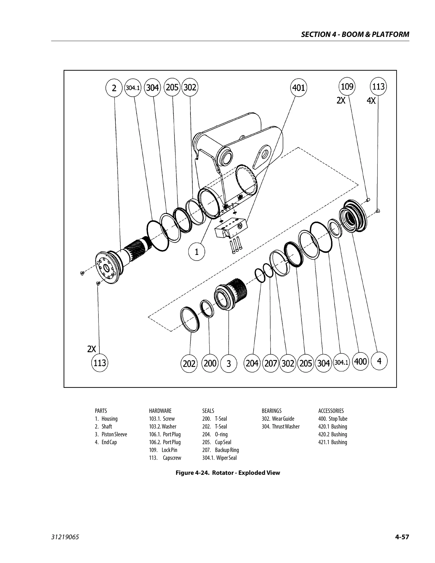
JLG 800AJ PVC 2107 Service and Maintenance Manual 31219065 Rev A - 2021 PDF — PDF page 369 preview
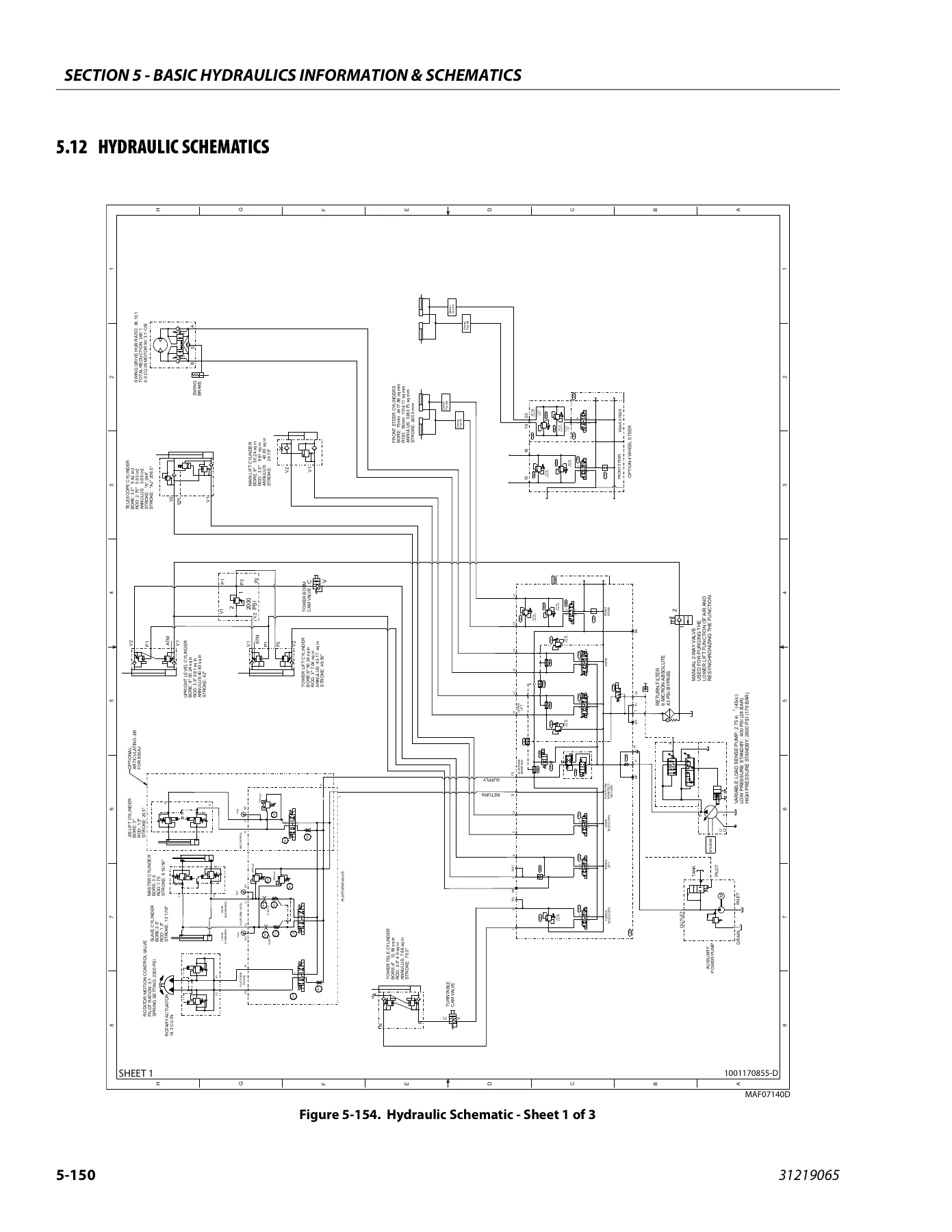
JLG 800AJ PVC 2107 Service and Maintenance Manual 31219065 Rev A - 2021 PDF — PDF page 540 preview

Illustrations, Schematics and Diagnostic References

The 656-page JLG 800AJ PVC 2107 Service and Maintenance Manual 31219065 Rev A – 2021 PDF contains extensive visual service material. Examples include maintenance and lubrication diagrams, chassis and turntable component locations, drive motor cross-sections, swing drive and bearing illustrations, engine installation sheets, boom and powertrack drawings, rotator exploded and assembly views, hydraulic-cylinder service drawings, pressure-adjustment illustrations, hydraulic schematics, analyzer flow charts, control-module connection information, engine and accessory harness diagrams, and a 12-sheet electrical schematic sequence.

Diagnostic material is distributed through the systems where it is needed. The manual includes drive-motor and generator troubleshooting, engine fault-code material, UMS troubleshooting and DTCs, SkyGuard diagnostics, hydraulic pump fault logic, LSS troubleshooting, analyzer diagnostic menus, and JLG Control System diagnostic trouble codes. This makes the document useful not only for dismantling and reassembly but also for narrowing down faults before major components are removed.

Get the JLG 800AJ Manual Instantly

This manual supports maintenance, inspection, adjustment, troubleshooting, component overhaul, hydraulic service, boom and platform repair, drive and swing work, control-system diagnosis, and electrical fault tracing on the JLG 800AJ within the configurations covered by document 31219065. Using the specified procedures, torque data, service limits, lubrication information, pressure-setting guidance, diagnostic references, and schematics helps keep repair work tied to the technical information provided for the machine rather than relying on guesswork.

Purchase the JLG 800AJ PVC 2107 Service and Maintenance Manual 31219065 Rev A – 2021 PDF for instant digital delivery after payment. There is no physical book and no shipping delay. The PDF can be opened on a computer, tablet, or phone and pages can be printed when a paper reference is more convenient at the machine or workbench.
Reviews

There are no reviews yet.

Be the first to review “JLG 800AJ PVC 2107 Service and Maintenance Manual 31219065 Rev A – 2021 PDF”

What Our Customers Say

★★★★★ Live reviews from customers
Loading customer reviews...
0
    0
    Your Cart
    Your cart is emptyReturn to Shop
    🛒
    Recently Purchased
    🕒 verified order