★ TRUSTED BY 321,897+ PROFESSIONALS WORLDWIDE
🏢
Trusted Business
Verified & Licensed
🛡️
Virus Free Files
100% Safe Downloads
🔒
Secure Payment
SSL Protected
Instant Delivery
Available Immediately
Sale!

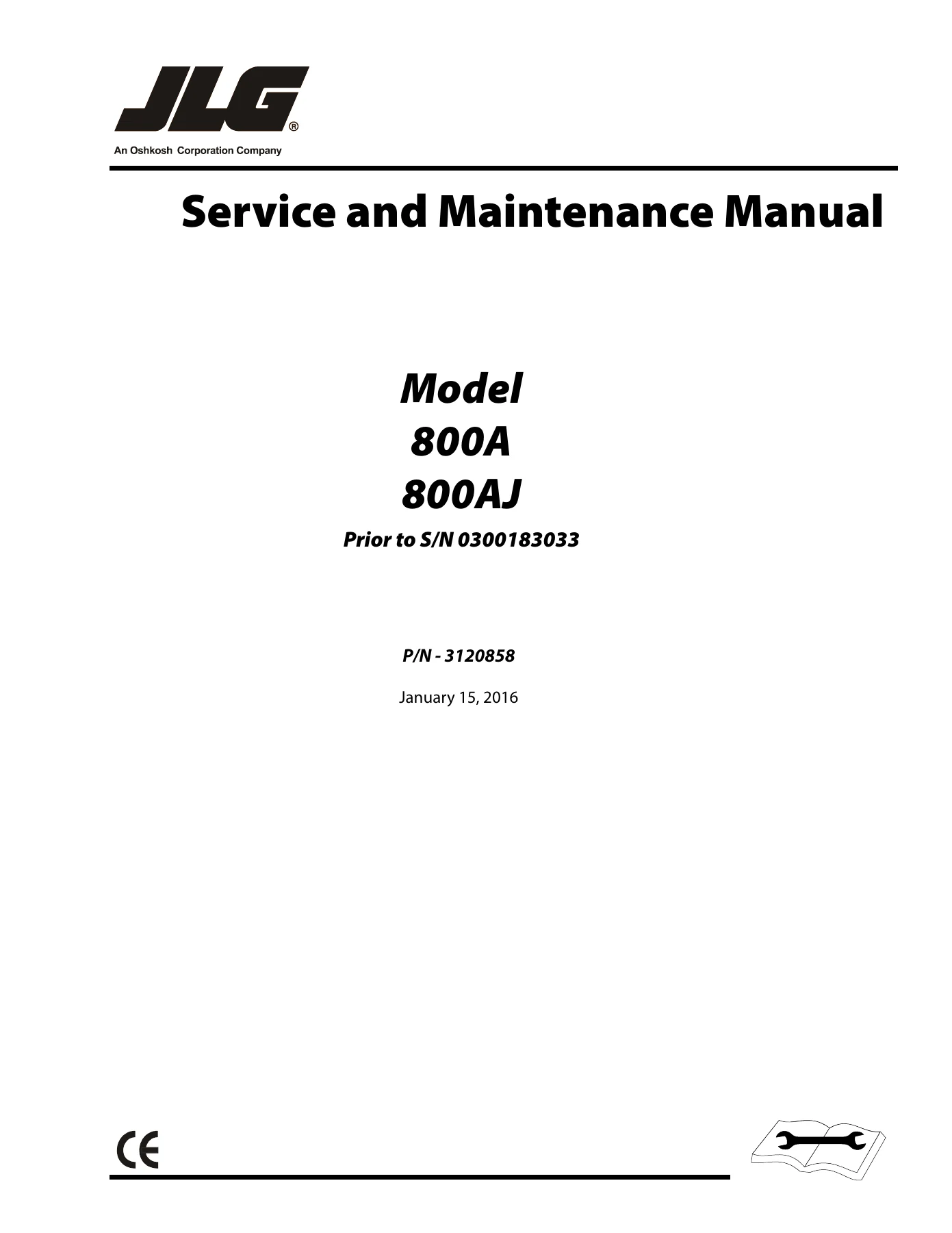
JLG 800A 800AJ Service & Maintenance Manual Prior to S/N 0300183033 – P/N 3120858 (2016)

Original price was: $44.95.Current price is: $27.95.

494-page JLG Service and Maintenance Manual for 800A and 800AJ models prior to S/N 0300183033. P/N 3120858, revised January 15, 2016, with specifications, maintenance schedules, component repair procedures, JLG control-system diagnostics, hydraulic schematics and electrical schematics.

SKU: HD-JLG-800A-800AJ-3120858 Category: Tags: , , , Vendor: Drill Rig Docs
Instant PDF Download
Available immediately
💾
Save to Your Device
Download & keep forever
🛡️
Antivirus Scanned
100% virus-free
🌍
Trusted Worldwide
175,000+ customers

Description

JLG 800A 800AJ Service & Maintenance Manual Prior to S/N 0300183033 – P/N 3120858 (2016)

This 494-page service and maintenance reference covers the JLG 800A and JLG 800AJ aerial platforms prior to S/N 0300183033. Revised January 15, 2016 under publication number 3120858, it brings together operating specifications, scheduled maintenance information, component repair procedures, hydraulic service data, JLG control-system diagnostics, and electrical and hydraulic schematics in one detailed document. The JLG 800A 800AJ Service & Maintenance Manual Prior to S/N 0300183033 – P/N 3120858 (2016) is especially useful when work goes beyond routine checks and requires serial-number-specific procedures, settings, troubleshooting information, or component disassembly and reassembly guidance.

File Details

  • Manual type: Service and Maintenance Manual
  • Brand: JLG
  • Models: 800A and 800AJ
  • Serial coverage: Prior to S/N 0300183033
  • Publication number: 3120858
  • Revision date: January 15, 2016
  • Original issue: August 1998
  • Language: English
  • Pages: 494
  • File format: PDF

Service Data and Maintenance Reference

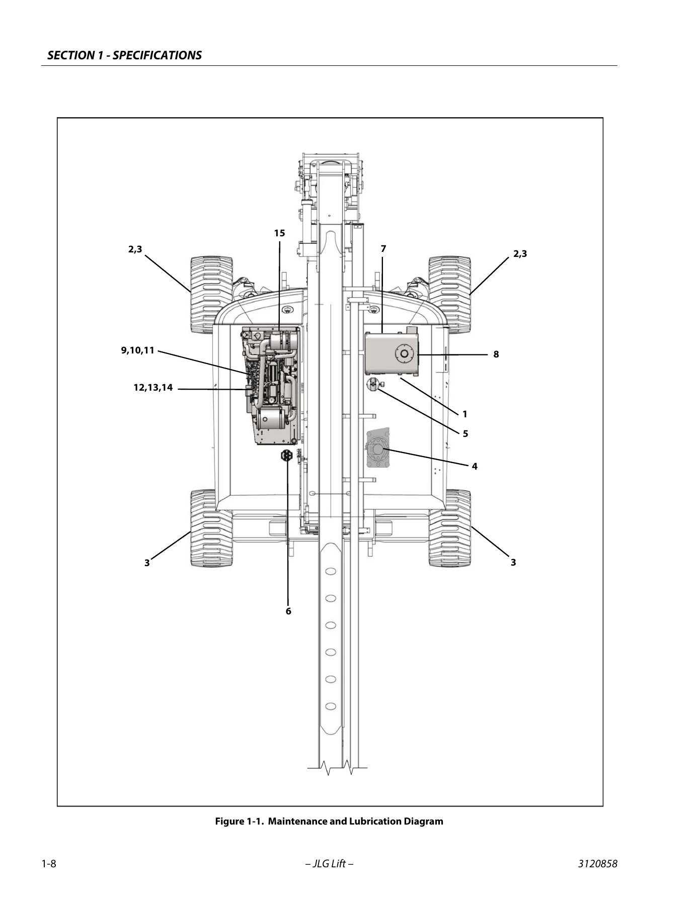
The opening specification material gives technicians a working baseline before repair work begins. It includes operating specifications, fluid capacities, tire data, drive and swing system information, pump specifications, torque requirements, hydraulic-oil guidance, cylinder dimensions, major component weights, critical stability weights, and a maintenance and lubrication program. Engine data is provided for Deutz F4M2011F, Deutz D2011L04, Caterpillar 3044C/3.4 and Isuzu 4JB1 configurations, while later service sections also include Ford LRG425-related adjustment information. The manual also supplies SAE and metric fastener torque charts and lubrication intervals for items such as swing bearings, wheel bearings, drive hubs, filters, hydraulic tank, engine oil, fuel filters and air filter.

Inspection guidance extends from pre-start and pre-delivery checks through frequent inspections, annual machine inspection and preventive maintenance. Service guidelines address cleanliness, bearings, gaskets, bolt usage, hydraulic lines, electrical wiring, hydraulic-system contamination, lubrication and battery care. Cylinder drift testing, pin and composite-bearing repair guidance, and welding precautions are also included. This makes the JLG 800A 800AJ service manual useful not only for a major repair but also for establishing the checks and service practices that surround that repair.

Chapters Covered

  • Introduction – Maintenance Safety Precautions
    • General maintenance safety
    • Hydraulic system safety
    • Maintenance precautions
  • Section 1 – Specifications
    • Operating specifications and capacities
    • Component and engine data
    • Tires, drive system and swing system
    • Hydraulic drive, variable-displacement, load-sense and auxiliary pumps
    • Torque requirements and hydraulic-oil information
    • Cylinder specifications, component weights and critical stability weights
    • Maintenance and lubrication
  • Section 2 – General
    • Machine preparation, inspection and maintenance
    • Service guidelines and workmanship
    • Lubrication and hydraulic-system information
    • Cylinder drift test
    • Pins and composite-bearing repair guidelines
    • Welding on JLG equipment
  • Section 3 – Chassis & Turntable
    • Tires and wheels; oscillating axle bleeding and lockout testing
    • Free wheeling and emergency towing preparation
    • Drive torque hub, drive brakes and drive motors
    • Swing bearing, swing gear backlash, swing hubs, brakes and motors
    • Rotary coupling and tilt alarm switch
    • Generator and dual-fuel system service
    • EFI diagnostics, ECM and sensor information
    • Ford LPG system and Ford LRG425 governor adjustments
    • Deutz throttle checks and Deutz EMR 2 diagnostics

    IMAGES PREVIEW

    JLG 800A 800AJ Service & Maintenance Manual Prior to S/N 0300183033 - P/N 3120858 (2016) — PDF page 1 preview
    JLG 800A 800AJ Service & Maintenance Manual Prior to S/N 0300183033 - P/N 3120858 (2016) — PDF page 28 preview
    JLG 800A 800AJ Service & Maintenance Manual Prior to S/N 0300183033 - P/N 3120858 (2016) — PDF page 59 preview

  • Section 4 – Boom & Platform
    • Platform, rotator and slave cylinder
    • Upper boom powertrack and powertrack maintenance
    • Upper boom, upright and tower boom assembly
    • Upright Monitoring System calibration and troubleshooting
    • Articulating jib and tower-boom hose replacement
    • Limit-switch and boom-valve adjustments
    • Wear pads and rotator service
    • Drive-card setup and load-sensing system calibration
    • Foot switch adjustment
  • Section 5 – Basic Hydraulic Information and Schematics
    • O-ring lubrication and hydraulic valve theory
    • Holding-valve checks and cylinder theory
    • Cylinder checking, repair, removal and installation
    • Hydraulic pump-drive coupling lubrication
    • Pressure setting procedures and hydraulic oil change-out
    • Hydraulic component start-up procedures
    • Rexroth variable-displacement pump service
    • Sauer piston pump troubleshooting and service
    • Hydraulic schematics for applicable drive and serial configurations
  • Section 6 – JLG Control System
    • Control-system introduction and CANbus communications
    • Hand-held analyzer connection and use
    • Analyzer access levels and parameter adjustment
    • Machine setup and level-vehicle configuration
    • Machine personality settings and function speeds
    • Fault-code and diagnostic menu information
  • Section 7 – Electrical Information & Schematics
    • Multimeter basics and electrical measurement techniques
    • Dielectric compound application and connector servicing
    • AMP connector assembly and disassembly
    • Deutsch DT/DTP and HD30/HDP20 connector service
    • Electrical component installation drawings and engine-specific schematics

Taken as a whole, the manual follows the machine from routine inspection and lubrication into major mechanical, hydraulic and electrical work. Chassis and turntable coverage includes serial-dependent drive brake, drive motor, swing hub, swing brake and swing motor procedures. Boom and platform coverage moves through structural assemblies, powertrack, upright monitoring, jib, limit switches, wear pads, rotator and load-sensing adjustments. The hydraulic section contains extensive cylinder repair procedures and system schematics, while the control-system section adds analyzer setup, configuration programming, function-speed information and fault-code references. Electrical pages then provide connector service guidance together with installation drawings and schematics for the engine and control configurations covered by the manual.

Detailed Repair, Diagnostics and Schematics

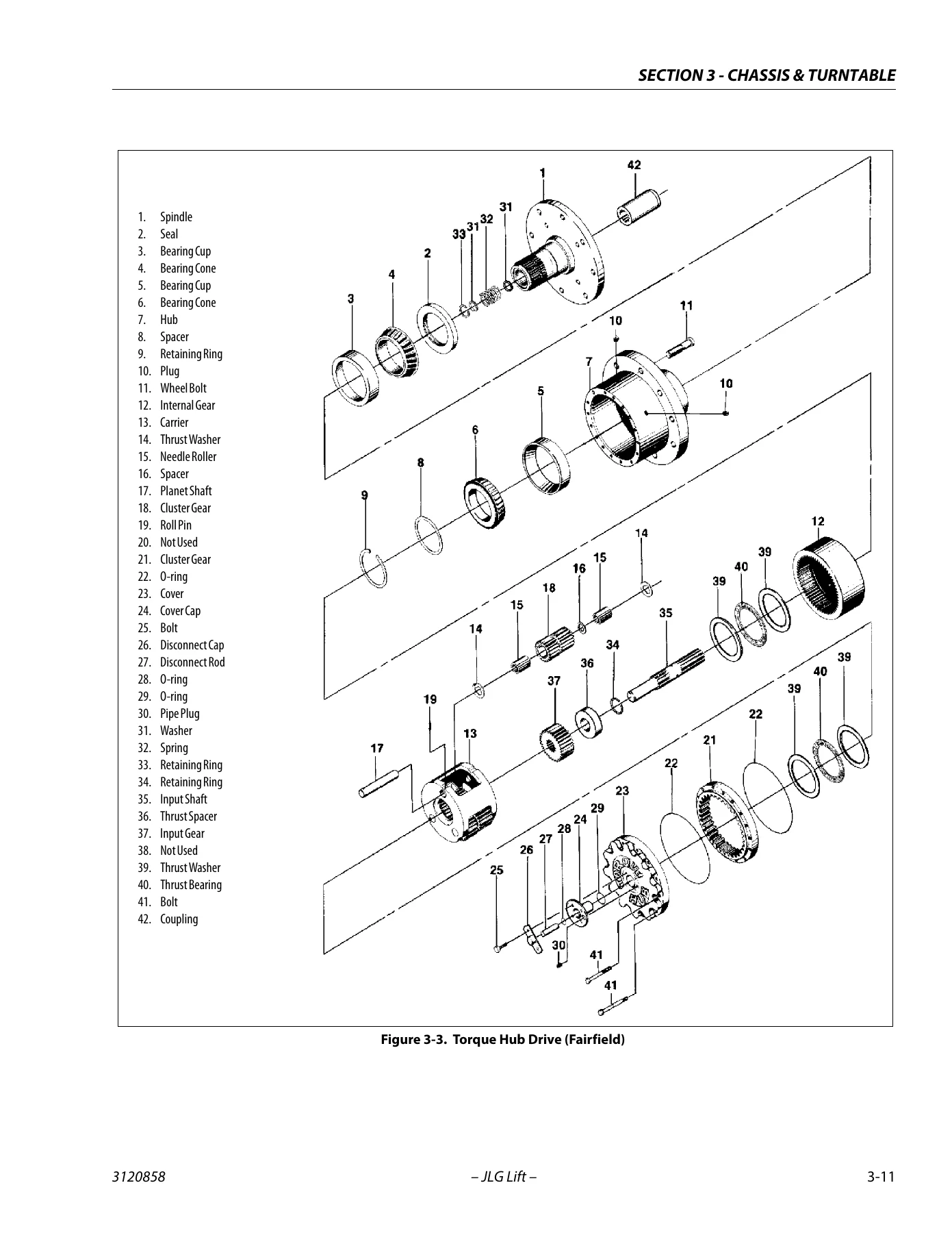
Many procedures are presented as step-by-step disassembly, inspection, repair, assembly, installation or adjustment sequences. Examples include the drive torque hub, multiple drive-brake versions, drive motors, swing bearing and swing components, upper and tower boom assemblies, rotator assemblies, hydraulic cylinders and hydraulic pumps. Exploded views and component illustrations support these procedures, and the manual repeatedly distinguishes between different serial-number ranges where hardware or procedures changed.

Complete PDF Bookmark Tree

Complete Bookmarks

The complete bookmarks in the “JLG 800A 800AJ Service & Maintenance Manual Prior to S/N 0300183033 – P/N 3120858 (2016)” are as follows:

Service Manual_3120858p. 1
Table of Contentsp. 5
List of Figuresp. 12
List of Tablesp. 19
Section A. Introduction – Maintenance Safety Precautionsp. 3
A Generalp. 3
B Hydraulic System Safetyp. 3
C Maintenancep. 3
Section 1. Specificationsp. 21
1.1 Operating specificationsp. 21
Capacitiesp. 21
1.2 Component Datap. 21
Engine Datap. 21
Tiresp. 22
Drive System (Prior to S/N 0300083332)p. 23
Drive System (S/N 0300083332 to S/N 0300183033, S/N 0300000100)p. 23
Swing Systemp. 23
Hydraulic Drive Pumpp. 23
Variable Displacement Pumpp. 23
Hydraulic Load Sense Pumpp. 23
Auxiliary Power Pumpp. 23
Hydraulic Filter – In-linep. 23
1.3 TOrque Requirementsp. 24
1.4 Lubricationp. 24
Hydraulic Oilp. 24
1.5 Cylinder Specificationsp. 26
1.6 Major Component Weightsp. 26
Critical Stability Weightsp. 27
1.7 Maintenance and Lubricationp. 29
Section 2. Generalp. 39
2.1 Machine Preparation, Inspection, and Maintenancep. 39
Generalp. 39
Preparation, Inspection, and Maintenancep. 39
Pre-Start Inspectionp. 39
Pre-Delivery Inspection and Frequent Inspectionp. 39
Annual Machine Inspectionp. 39
Preventative Maintenancep. 39
2.2 Service and Guidelinesp. 40
Generalp. 40
Safety and Workmanshipp. 40
Cleanlinessp. 40
Components Removal and Installationp. 40
Component Disassembly and Reassemblyp. 40
Pressure-Fit Partsp. 40
Bearingsp. 41
Gasketsp. 41
Bolt Usage and Torque Applicationp. 41
Hydraulic Lines and Electrical Wiringp. 41
Hydraulic Systemp. 41
Lubricationp. 41
Batteryp. 41
Lubrication and Servicingp. 41
2.3 Lubrication and Informationp. 41
Hydraulic Systemp. 41
Hydraulic Oilp. 42
Changing Hydraulic Oilp. 42
Lubrication Specificationsp. 42
2.4 Cylinder Drift Testp. 42
Platform Driftp. 42
Cylinder Driftp. 42
2.5 Pins and Composite Bearing Repair Guidelinesp. 42
2.6 Welding on JLG Equipmentp. 43
Do the Following When Welding on JLG Equipmentp. 43
Do NOT Do the Following When Welding on JLG Equipmentp. 43
Section 3. Chassis & Turntablep. 49
3.1 Tires & Wheelsp. 49
Tire Inflationp. 49
Tire Damagep. 49
Tire Replacementp. 49
Wheel Replacementp. 49
Wheel Installationp. 49
3.2 Oscillating Axle Bleeding Procedure And Lockout Testp. 50
Lockout Cylinder Bleedingp. 50
Oscillating Axle Lockout Testp. 51
3.3 Free Wheeling Optionp. 51
To Disengage Drive Motors and Brakes (Free Wheel) for Emergency Towingp. 51
To Engage Drive Motors and Brakes (Normal Operation)p. 51
3.4 Torque Hub, Drivep. 52
Disassemblyp. 52
Cleaning and Inspectionp. 52
Repairp. 52
Assemblyp. 54
3.5 Drive Brake – Ausco (Prior to S/N 0300056875)p. 60
Disassemblyp. 60
Inspectionp. 60
Assemblyp. 60
3.6 Drive Brake – Mico (S/N 0300056875 to S/N 0300083332)p. 62
Disassemblyp. 62
Assemblyp. 62
Bleedingp. 65
3.7 Drive Brake (S/N 0300083332 to S/N 0300183033)p. 66
Disassemblyp. 66
Inspectionp. 66
Assemblyp. 66
3.8 Drive Motor (Prior to S/N 0300083332)p. 68
Spare Parts Kitsp. 68
Replacing the Drive Shaft Sealp. 69
Disassembly and Assemblyp. 70
Assembly Notesp. 74
Taper Roller Bearing Initial Tensionp. 74
Testing and Setupp. 76
3.9 Drive Motor Adjustment Procedure (Prior to S/N 0300083332)p. 76
3.10 Drive Motor (S/N 0300083332 to S/N 0300183033)p. 77
Descriptionp. 77
Shaft Seal Replacementp. 77
Loop Flushing Valvep. 78
Troubleshootingp. 79
Disassemblyp. 80
Inspectionp. 84
Assemblyp. 86
Initial Start-up Proceduresp. 91
3.11 Swing Bearingp. 92
Turntable Bearing Mounting Bolt Condition Checkp. 92
Wear Tolerancep. 95
Swing Bearing Replacementp. 95
Swing Bearing Torque Valuesp. 96
3.12 Procedure for setting swing gear backlashp. 100
3.13 Swing Hub (Prior to S/N 0300068040)p. 101
Disassemblyp. 101
Assemblyp. 102
Hub Shaft Sub-Assemblyp. 104
Carrier Sub-Assemblyp. 106
3.14 Swing Brake – Ausco (Prior to S/N 0300064566)p. 109
Disassemblyp. 109
Inspectionp. 109
Assemblyp. 109
3.15 Swing Motor (Eaton) (Prior to S/N 0300068040)p. 111
Disassemblyp. 111
Reassemblyp. 112
Motor Timingp. 113
3.16 Swing Hub (S/N 0300068040 to S/N 0300183033)p. 115
Disassemblyp. 115
Main Assembly Procedurep. 115
Hub Shaft Sub-Assemblyp. 118
Carrier Sub-Assemblyp. 120
3.17 Swing Brake (S/N 0300068040 to S/N 0300183033)p. 123
Disassemblyp. 123
Assemblyp. 123
3.18 Swing Motor (S/N 0300068040 to S/N 0300183033)p. 125
Disassemblyp. 125
Inspection and Cleaningp. 127
Assemblyp. 127
Timing Procedurep. 129
3.19 Rotary Couplingp. 132
3.20 Tilt Alarm Switch (Prior to S/N 0300065534)p. 137
Manual Adjustmentp. 137
3.21 Spark Arrester Cleaning Instructionsp. 137
3.22 Generatorp. 138
Every 250 hoursp. 138
Every 500 hoursp. 138
Overload Protectionp. 138
Inspecting Brushes, Replacing Brushes, and Cleaning Slip Ringsp. 138
3.23 Dual Fuel Systemp. 140
Changing from Gasoline to LP Gasp. 140
Changing from LP Gas to Gasolinep. 140
3.24 EFI Enginep. 140
Performing Diagnosticsp. 140
EFI Diagnostics (Prior to S/N 0300065534)p. 141
ECM and Sensorsp. 141
Engine Performance Module (EPM)p. 147
Fuel Systemp. 152
3.25 Ford LPG System (S/N 0300077500 To S/n 03000140000)p. 156
Descriptionp. 156
Regulatorp. 156
Megajectorp. 156
Mixerp. 156
Lockoff Solenoidp. 158
Megajector Diagnostic Code Descriptionsp. 158
3.26 Electric Governor Installation And Adjustments – Ford LRG425 Engine (Prior to S/N 0300065534)p. 159
Generalp. 159
Quick-start Installationsp. 159
Mounting-Actuatorp. 159
Linkagep. 159
Mounting-Controllerp. 160
Wiringp. 160
Power Distributionp. 160
Check-Out and Initial Start-Up Proceduresp. 161
Troubleshootingp. 164
Automatic Choke Adjustment Procedurep. 166
3.27 Throttle Checks And Adjustments – Deutz Engine (Prior to S/N 0300065534)p. 166
Generalp. 166
Procedurep. 167
Controller Statusp. 167
Failure Modesp. 167
3.28 Deutz EMR 2 (S/N 0300085331 to S/N 0300183034)p. 168
Section 4. Boom & Platformp. 181
4.1 Platformp. 181
Support Removalp. 181
Support Installationp. 182
Platform Sections Replacementp. 182
4.2 Rotator and Slave Cylinderp. 183
Removalp. 183
4.3 Upper Boom Powertrackp. 184
Removalp. 184
4.4 BOOM CLEANLINESS GUIDELINESp. 184
4.5 Powertrack Maintenancep. 189
Flat Bar Removalp. 189
Round Bar/Poly Bar Removalp. 189
Removing and Installing Linksp. 190
Installing a New Flat Barp. 193
Installing a New Round Bar/Poly Rollerp. 194
Replacing a Fixed End Bracketp. 194
Replacing a Moving End Bracketp. 195
Replacing a One Piece Bracketp. 195
4.6 Upper Boomp. 196
Removalp. 196
Disassemblyp. 197
Inspectionp. 198
Assemblyp. 198
Installationp. 198
4.7 Uprightp. 199
Removalp. 199
Installationp. 200
4.8 Tower Boom Assemblyp. 200
Removalp. 200
Inspectionp. 201
Assemblyp. 201
Installationp. 202
Tower Out of Syncp. 203
4.9 Upright Monitoring Systemp. 205
Re-Synchronizing Uprightp. 205
Calibration – Pre ADE Machinesp. 207
Calibration – ADE Equipped Machinesp. 211
Calibration Faultsp. 215
Function Checkp. 216
Service Mode/Tower Boom Retrievalp. 217
4.10 UMS Troubleshooting and Fault Messages – Non-ADE Machinesp. 223
Tower Lift Down Permanently Closedp. 223
Backward Stability Concern Messagep. 223
Forward Stability Concern Messagep. 223
UMS Out of Usable Range Messagep. 223
Battery Voltage < 9.0 Voltsp. 223
Battery Voltage > 16.0 Voltsp. 223
UMS Sensor Not Calibrated Messagep. 224
UMS Sensor Faultedp. 224
Tower Lift Down Output Short to Ground or Open Circuitp. 224
Tower Lift Down Output Short to Batteryp. 224
Platform Indicator Output Short to Ground or Open Circuitp. 224
Platform Indicator Output Short to Batteryp. 224
Ground Indicator Output Short to Groundp. 224
Ground Indicator Output Short to Batteryp. 224
Turntable Sensor Not Calibrated Messagep. 224
Turntable Sensor Faultedp. 225
EEPROM checksums failurep. 225
4.11 UMS Troubleshooting and Fault Messages – ADE Machinesp. 225
Backward Stability Concern Messagep. 225
Forward Stability Concern Messagep. 225
Auto Detection Input Low Messagep. 225
UMS Sensor Communications lostp. 225
Out of Usable Range Messagep. 226
UMS Sensor Not Calibrated Messagep. 226
UMS Sensor Faulted Messagep. 226
Incompatible Software Detected Messagep. 226
Calibration Faultsp. 226
4.12 Articulating Jibp. 227
Removalp. 227
Disassemblyp. 227
Inspectionp. 227
Assemblyp. 228
4.13 Sequence For Hose Replacement In The Tower Boomp. 228
4.14 Limit Switches Adjustmentp. 228
Upper Boom Horizontal Limit Switchp. 228
Tower Boom Horizontal Limit Switchp. 228
Dual Capacity Angle Limit Switch (800A only)p. 234
Upper Boom Length Switch (800 A only)p. 234
4.15 Boom Valve Adjustmentp. 234
4.16 Wear Padsp. 235
Tower Boomp. 235
Upper Boomp. 235
4.17 Rotator (Prior to S/N 0300067538)p. 235
Disassemblyp. 235
Inspectionp. 236
Assemblyp. 237
4.18 Rotator Assembly (S/N 0300067538 to S/N 0300183033)p. 239
Theory of Operationp. 239
Required Toolsp. 239
Disassemblyp. 242
Inspectionp. 246
Assemblyp. 246
Installing Counterbalance Valvep. 252
Testing the Actuatorp. 253
Installation and Bleedingp. 253
Troubleshootingp. 254
4.19 Drive Card Setup Proceduresp. 255
Lift, Swing, and Drive Cardsp. 255
Flow Control Cardp. 255
4.20 Load Sensing System machines built to s/n 0300062045p. 257
Functional Checkp. 258
Calibrationp. 258
4.21 Load Sensing System machines built s/n 0300062045 to S/N0300067883p. 259
Calibrationp. 259
4.22 Foot Switch Adjustmentp. 259
Upright Level Cylinderp. 273
Jib Lift Cylinderp. 279
Main Boom Lift Cylinderp. 285
Section 5. Basic Hydraulic Information and Schematicsp. 261
5.1 Lubricating O-Rings in the Hydraulic Systemp. 261
Cup and Brushp. 261
Dip Methodp. 262
Spray Methodp. 262
Brush-on Methodp. 262
5.2 Valves – Theory Of Operationp. 263
Solenoid Control Valve – Rexrothp. 263
Relief Valvesp. 263
5.3 Holding Valve Checksp. 263
5.4 Cylinders – Theory Of Operationp. 264
Systems Incorporating Double Acting Cylindersp. 264
Systems Incorporating Holding Valvesp. 264
5.5 Cylinder Checking Procedurep. 265
Cylinders Without Counterbalance Valves – Master Cylinder and Steer Cylindersp. 265
Cylinders With Single Counterbalance Valvep. 265
Cylinders With Dual Counterbalance Valvesp. 266
5.6 Cylinder Repairp. 267
Axle Lockout Cylinderp. 267
5.7 Cylinder Removal And Installationp. 334
Main Boom Telescope Cylinder Removalp. 334
Main Boom Telescope Cylinder Installationp. 335
Main Lift Cylinder Removalp. 335
Main Lift Cylinder Installationp. 335
Upright Level Cylinder Removalp. 336
Upright Level Cylinder Installationp. 336
Tower Boom Lift Cylinder Removalp. 337
Tower Lift Cylinder Installationp. 337
Tower Telescope Cylinder Removalp. 337
Tower Telescope Cylinder Installationp. 337
Slave Cylinder Removalp. 338
Slave Cylinder Installationp. 338
5.8 Hydraulic Pump W/hayes Pump drive Coupling Lubricationp. 338
5.9 Pressure Setting Proceduresp. 338
FIRST: Set Up the Function Pumpp. 338
SECOND: Adjustments Made at the Main Valve Blockp. 345
5.10 Hydraulic oil change-out procedurep. 346
5.11 Hydraulic Component Start-Up Procedures and Recommendationsp. 347
5.12 Rexroth Variable Displacement Pump (Prior to S/N 0300121643)p. 348
5.13 Sauer Piston Pump (S/N 0300121643 to S/N 0300183033)p. 350
Initial start-up proceduresp. 351
Troubleshootingp. 351
Shaft Seal Replacementp. 355
Control Assemblyp. 355
Plug and Fitting Sizes and Torquesp. 357
Tower Lift Cylinderp. 291
Master Cylinder – 800Ap. 297
Assemblyp. 300
Master Cylinder – 800 AJp. 303
Slave Cylinderp. 309
Steer Cylinderp. 315
Main Telescope Cylinderp. 322
Tower Telescope Cylinderp. 328
Section 6. JLG Control System (S/N 0300065534 to S/N 0300183033)p. 371
6.1 Introductionp. 371
6.2 CANbus Communicationsp. 390
6.3 To Connect the JLG Control System Analyzerp. 390
6.4 Using the Analyzerp. 390
6.5 Changing the Access Level of the Hand Held Analyzerp. 391
6.6 Adjusting Parameters Using the Hand Held Analyzerp. 392
6.7 Machine Setupp. 393
6.8 Level Vehicle Descriptionp. 393
6.9 Machine Personality Settingsp. 416
Function Speedsp. 416
Machine Orientation When Doing Speed Testsp. 416
Test Notesp. 416
Analyzer Diagnostics Menu Structurep. 442
Section 7. Electrical information & schematicsp. 447
7.1 Generalp. 447
7.2 Multimeter Basicsp. 447
Groundingp. 447
Backprobingp. 447
Min/Maxp. 447
Polarityp. 447
Scalep. 447
Voltage Measurementp. 447
Resistance Measurementp. 448
Continuity Measurementp. 448
Current Measurementp. 449
7.3 Applying Silicone Dielectric Compound to Electrical Connectionsp. 449
Installation of Dielectric Greasep. 450
Deutsch HD, DT, DTM, DRC Seriesp. 450
AMP Sealp. 450
AMP Mate-N-Lokp. 451
DIN Connectorsp. 451
Exclusionsp. 451
Brad Harrison / Phoenix Contact M12p. 452
AMP Junior Timerp. 452
7.4 AMP Connectorp. 453
Assemblyp. 453
Disassemblyp. 455
Wedge Lockp. 455
Service – Voltage Readingp. 455
7.5 Deutsch Connectorsp. 457
DT/DTP Series Assemblyp. 457
DT/DTP Series Disassemblyp. 457
HD30/HDP20 Series Assemblyp. 458
HD30/HDP20 Series Disassemblyp. 458

Troubleshooting is also a significant part of the coverage. The document includes drive-system troubleshooting, EFI diagnostic trouble codes, Deutz EMR 2 fault-code material, Upright Monitoring System fault messages for both non-ADE and ADE machines, hydraulic pump troubleshooting, JLG analyzer fault codes and diagnostic menu descriptions. Hydraulic schematics cover 2-wheel-drive, 4-wheel-drive and later serial configurations, while electrical schematics include Deutz, Isuzu, Caterpillar and other applicable system arrangements. For technicians tracing a fault rather than simply replacing a part, these diagnostic and schematic sections provide the relationships between controls, sensors, pumps, valves, wiring and machine functions.

Built Around Serial-Specific Service Work

The overall manual applies to 800A and 800AJ machines prior to S/N 0300183033, but many individual components are divided at earlier serial breaks. The contents identify different drive-brake, drive-motor, swing-hub, swing-brake, swing-motor, rotator, steering-cylinder, hydraulic-pump, electrical-installation and control-system configurations. Checking the machine serial number against the procedure heading is therefore an important part of using this manual correctly. That detail is valuable when the same model designation spans several component revisions.

Keep the Correct Service Information at Hand

The JLG 800A 800AJ Service & Maintenance Manual Prior to S/N 0300183033 – P/N 3120858 (2016) supports inspection, scheduled maintenance, hydraulic pressure checks, component removal and installation, cylinder rebuilding, drive and swing repairs, boom and platform service, control-system setup, fault diagnosis, and electrical or hydraulic troubleshooting. Having the specified procedures, torque information, capacities, adjustment data, fault references and schematics available helps technicians work from the values and sequences intended for the covered machine configuration instead of relying on memory or generic information.

After purchase, the manual is supplied as an instant PDF download – there is no shipping wait. Open it on a computer, tablet or phone, keep it available in the workshop, and print the pages needed for a particular service job.
Reviews

There are no reviews yet.

Be the first to review “JLG 800A 800AJ Service & Maintenance Manual Prior to S/N 0300183033 – P/N 3120858 (2016)”

What Our Customers Say

★★★★★ Live reviews from customers
Loading customer reviews...
0
    0
    Your Cart
    Your cart is emptyReturn to Shop
    🛒
    Recently Purchased
    🕒 verified order