★ TRUSTED BY 321,897+ PROFESSIONALS WORLDWIDE
🏢
Trusted Business
Verified & Licensed
🛡️
Virus Free Files
100% Safe Downloads
🔒
Secure Payment
SSL Protected
Instant Delivery
Available Immediately
Sale!

JLG E450AJ PVC 2001 Service and Maintenance Manual 31215013 Rev B

Original price was: $39.95.Current price is: $23.95.

Complete JLG E450AJ PVC 2001 Service and Maintenance Manual, document 31215013 Rev B dated 2020. Covers chassis, turntable, boom, platform, hydraulics, JLG control system and electrical schematics for the E450AJ mobile elevating work platform.

Instant PDF Download
Available immediately
💾
Save to Your Device
Download & keep forever
🛡️
Antivirus Scanned
100% virus-free
🌍
Trusted Worldwide
175,000+ customers

Description

JLG E450AJ PVC 2001 Service and Maintenance Manual – 31215013 Rev B

This is the full JLG E450AJ PVC 2001 Service and Maintenance Manual, document number 31215013, Revision B, dated October 01, 2020. It is the workshop-level reference for the E450AJ mobile elevating work platform, covering the chassis and turntable, boom and platform assemblies, hydraulic system, JLG control system and the complete electrical schematic set. Every section is written for the technician who has to inspect, adjust, disassemble, repair and re-assemble the machine correctly.

File Details

  • Manual type: Service and Maintenance Manual
  • Brand: JLG
  • Model: E450AJ (PVC 2001)
  • Document number: 31215013
  • Revision: Rev B
  • Date: October 01, 2020
  • Language: English
  • File format: PDF
  • Page count: 470 pages

Chapters Covered

The manual is organised into the following major sections:

IMAGES PREVIEW

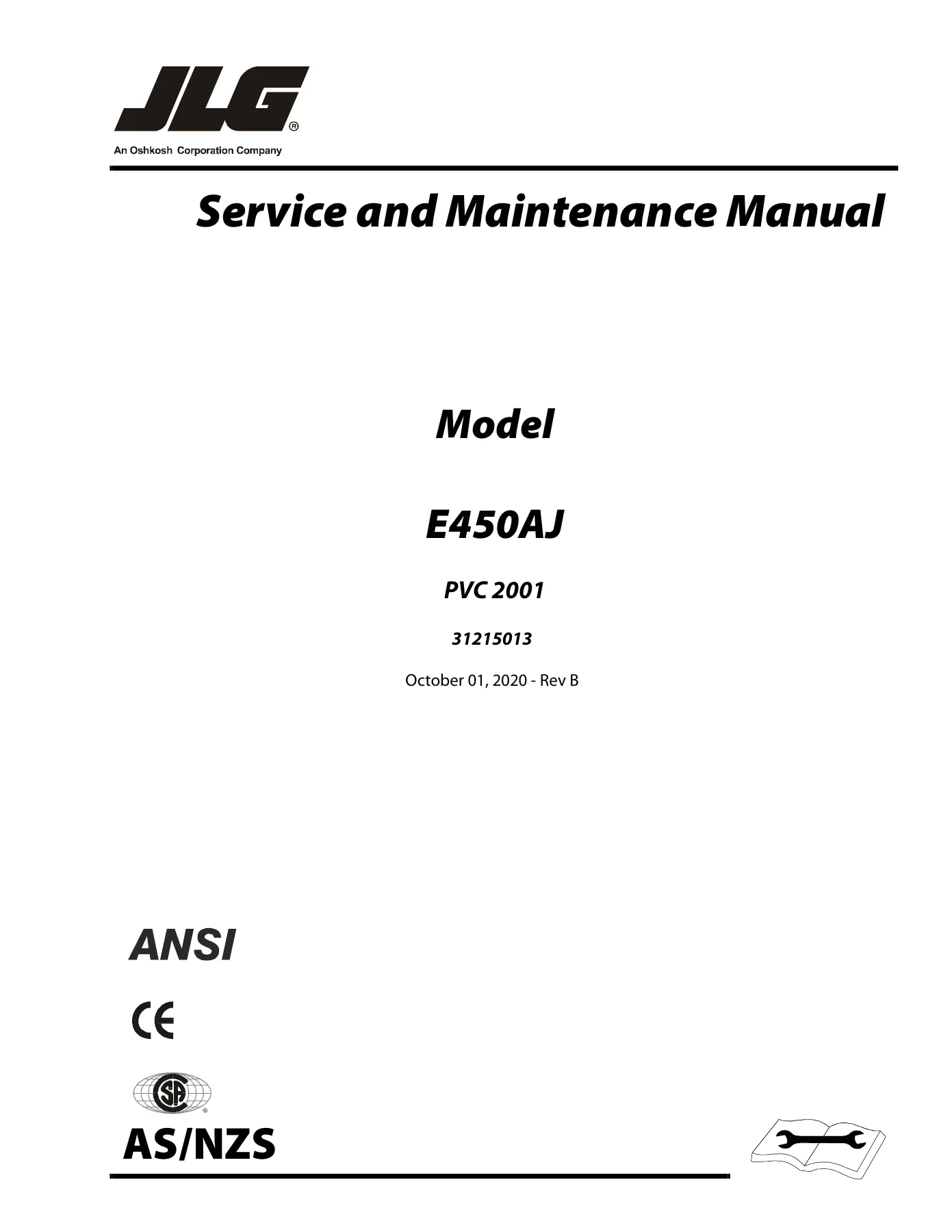
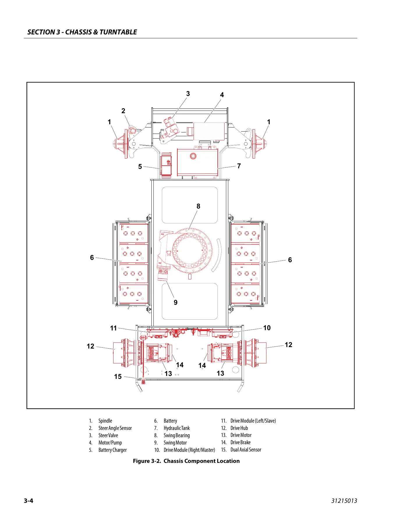
JLG E450AJ PVC 2001 Service and Maintenance Manual 31215013 Rev B — PDF page 1 preview
JLG E450AJ PVC 2001 Service and Maintenance Manual 31215013 Rev B — PDF page 22 preview
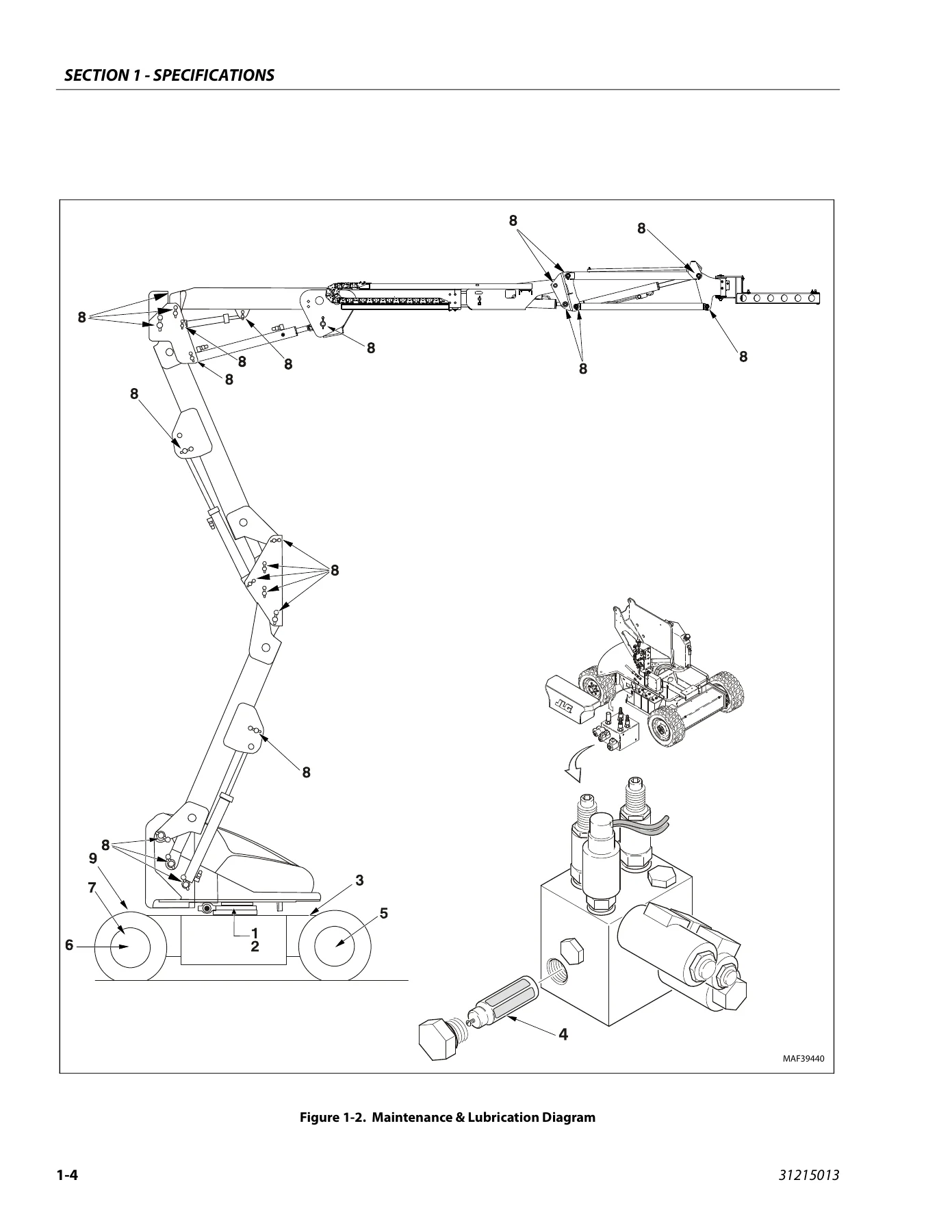
JLG E450AJ PVC 2001 Service and Maintenance Manual 31215013 Rev B — PDF page 50 preview

  • Section A – Introduction: Maintenance safety precautions, general safety, hydraulic system safety, maintenance warnings
  • Section 1 – Specifications: Operating specifications, machine specifications, tires, capacities, dimensional data, torque specifications, lubrication specifications, hydraulic oil, critical stability weights, major component weights, serial number locations, maintenance and lubrication, threadlocking compound, SAE and metric torque charts
  • Section 2 – General: Machine preparation, inspection and maintenance, pre-start inspection, pre-delivery inspection, frequent inspection, annual machine inspection, preventive maintenance, service and guidelines, cleanliness, component removal and installation, pressure-fit parts, bearings, gaskets, bolt usage and torque application, hydraulic lines and electrical wiring, hydraulic system, lubrication, battery, cylinder drift, cylinder leakage test, cylinder thermal drift, pins and composite bearing repair guidelines, welding on JLG equipment
  • Section 3 – Chassis & Turntable: Tires and wheels, tire damage, tire replacement, wheel replacement, wheel installation, spindle, wheel bearing end play, tilt module, speed sensor, drive hub, roll and leak testing, disassembly and assembly procedures, drive motor, swing bearing, turntable bearing mounting bolt condition check, wear tolerance, swing bearing replacement, swing bearing torque, worm gear end play, swing motor, battery maintenance and charging, battery charger, battery charger fault codes, battery charger algorithm, generator, engine, alternator, dynamo, voltage regulator, fuses, relays, glow plug, fuel pump, fuel solenoid, oil pressure switch, oil temperature sensor, alternator output current sensor, engine speed sensor, RBS engine/generator controller, alarms and flash codes, maintenance schedule, troubleshooting, APU engine start battery boosting, supplementary fuse for APU
  • Section 4 – Boom & Platform: Platform support removal and installation, rotator removal and installation, platform level cylinder, main boom powertrack removal and installation, boom maintenance, removal, disassembly, inspection, assembly, installation, wear pads, boom limit switches, boom cleanliness guidelines, articulating jib boom removal, disassembly, inspection, assembly, boom synchronizing procedure, foot switch adjustment, rotary actuator theory of operation, tools required, disassembly, inspection, assembly, installing counterbalance valve, greasing thrust washers, testing the actuator, installation and bleeding, troubleshooting, powertrack maintenance, removing a link, installing a new link, replacing fixed end brackets, replacing moving end brackets, SkyGuard operation, function test, diagnostics and troubleshooting, bolt-on external fall arrest inspection, installation
  • Section 5 – Basic Hydraulic Information & Schematics: Lubricating O-rings in the hydraulic system, hydraulic connection assembly and torque specification, tapered thread types, straight thread types, flange connection types, tightening methods, assembly and torque specifications, NPTF, BSPT, JIC, SAE, ORFS, DIN, bulkhead, ORB, MFF, MPP, BSPP, flange connections, double wrench method, FFWR and TFFT methods, adjustable stud end assembly, O-ring installation, hydraulic cylinders, platform level cylinder, jib lift cylinder, lower lift cylinder, mid lift cylinder, upper lift cylinder, master cylinder, steer cylinder, telescope cylinder, cylinder removal and installation, lower lift cylinder bleeding procedure, pressure setting procedures, main relief, main lift down relief, lower lift down relief, telescope relief, platform level up and down relief, steer relief, jib lift relief, releveling valve relief, hydraulic schematic
  • Section 6 – JLG Control System: JLG control system analyzer kit instructions, connecting the analyzer, using the analyzer, changing the access level, adjusting parameters, machine setup, level vehicle description, machine configuration programming information, machine personality settings, machine orientation when performing test, function speed, help descriptions and fault flash codes, analyzer diagnostics menu structure, system self test, calibrating steer, calibrating tilt sensor, calibrating load sensing, LSS system, diagnostic menu, calibration procedure, testing and evaluation, troubleshooting, resetting the MSSO system, drive cutout override service mode
  • Section 7 – Basic Electrical Information & Electrical Schematics: General, multimeter basics, grounding, backprobing, min/max, polarity, scale, voltage measurement, resistance measurement, continuity measurement, current measurement, checking switches, basic check, limit switches, automatic switches, switch wiring, applying silicone dielectric compound to electrical connections, dielectric grease application, AMP connector, DEUTSCH connectors, wiring harness connector labels, connector labels, component labels, electrical schematics

Complete PDF Bookmark Tree

Complete Bookmarks

The complete bookmarks in the “JLG E450AJ PVC 2001 Service and Maintenance Manual 31215013 Rev B” are as follows:

31215013_B_E450AJ _JLG_Service_Englishp. 1
Section A. Introduction – Maintenance Safety Precautionsp. 3
Revision Logp. 4
Table of Contentsp. 5
List of Figuresp. 12
List of Tablesp. 17
Section 1. Specificationsp. 19
1.1 Operating Specificationsp. 19
Machine Specificationsp. 19
1.2 Tiresp. 19
1.3 Capacitiesp. 19
1.4 Dimensional Datap. 19
1.5 Torque Specificationsp. 20
1.6 Lubrication Specificationsp. 20
Hydraulic Oilp. 20
1.7 Critical Stability Weightsp. 21
1.8 Major Component Weightsp. 21
1.9 Serial Number Locationsp. 21
1.10 Maintenance and Lubricationp. 23
1.11 Threadlocking Compoundp. 26
1.12 Torque Chartsp. 27
SAE Fastener Torque Chartp. 27
SAE Fastener Torque Chart (Continued)p. 28
SAE Fastener Torque Chart (Continued)p. 29
SAE Fastener Torque Chart (Continued)p. 30
SAE Fastener Torque Chart (Continued)p. 31
SAE Fastener Torque Chart (Continued)p. 32
Metric Fastener Torque Chartp. 33
Metric Fastener Torque Chart (Continued)p. 34
Metric Fastener Torque Chart (Continued)p. 35
Metric Fastener Torque Chart (Continued)p. 36
Section 2. Generalp. 37
2.1 Machine Preparation, Inspection, and Maintenancep. 37
Generalp. 37
Preparation, Inspection, and Maintenancep. 37
Pre-Start Inspectionp. 37
Pre-Delivery Inspection and Frequent Inspectionp. 37
Annual Machine Inspectionp. 37
Preventative Maintenancep. 37
2.2 Service and Guidelinesp. 38
Generalp. 38
Safety and Workmanshipp. 38
Cleanlinessp. 38
Components Removal and Installationp. 38
Component Disassembly and Assemblyp. 39
Pressure-Fit Partsp. 39
Bearingsp. 39
Gasketsp. 39
Bolt Usage and Torque Applicationp. 39
Hydraulic Lines and Electrical Wiringp. 39
Hydraulic Systemp. 39
Lubricationp. 39
Batteryp. 39
Lubrication and Servicingp. 39
2.3 Lubrication and Informationp. 40
Hydraulic Systemp. 40
Hydraulic Oilp. 40
Changing Hydraulic Oilp. 40
Lubrication Specificationsp. 40
2.4 Cylinder Driftp. 41
Theoryp. 41
Cylinder Leakage Testp. 41
Cylinder Thermal Driftp. 41
2.5 Pins and Composite Bearing Repair Guidelinesp. 42
2.6 Welding on JLG Equipmentp. 42
Do the Following When Welding on JLG Equipmentp. 42
Do NOT Do the Following When Welding on JLG Equipmentp. 42
Section 3. Chassis & Turntablep. 47
3.1 Tires & Wheelsp. 47
Tire Damagep. 47
Tire Replacementp. 47
Wheel Replacementp. 47
Wheel Installationp. 47
3.2 Spindlep. 48
Setting Wheel Bearing End Playp. 48
Specificationsp. 48
Checkingp. 48
Greasing Requirementsp. 48
3.3 Tilt Modulep. 51
3.4 Speed Sensorp. 52
3.5 Drive Hubp. 59
Roll and Leak Testingp. 59
Tightening and Torquing Boltsp. 59
Main Disassemblyp. 60
Output Carrier Disassemblyp. 62
Input Carrier Disassemblyp. 64
Hub-spindle Disassemblyp. 65
Cover Disassemblyp. 66
Input Carrier Assemblyp. 67
Output Planet Gear Assemblyp. 67
Output Carrier Assemblyp. 68
Hub-spindle Assemblyp. 68
Cover Assemblyp. 69
Main Assemblyp. 69
3.6 Drive Motorp. 72
Removalp. 72
Disassemblyp. 72
Inspectionp. 72
Assemblyp. 73
Installationp. 73
3.7 Swing Bearingp. 75
Turntable Bearing Mounting Bolt Condition Checkp. 75
Wear Tolerancep. 76
Replacement of Swing Bearingp. 77
Swing Bearing Torque Valuep. 80
Checking Worm Gear End Playp. 80
Adjusting End Playp. 80
3.8 Swing Motorp. 82
Preparation Before Disassemblyp. 85
Disassembly and Inspectionp. 85
Assemblyp. 92
One Piece Stator Constructionp. 98
Two Piece Stator Constructionp. 99
Final Checksp. 99
3.9 Battery Maintenance and Chargingp. 100
Battery Maintenance, Quarterlyp. 100
Optional On Board Generatorp. 100
Battery Charging (On Board Charger)p. 100
3.10 Battery Chargerp. 102
Operating Instructionsp. 102
Maintenance Instructionsp. 103
Battery Charger Fault Codesp. 103
Excessive Battery Watering Requirements or Strong Sulphur (Rotten Egg) Smellp. 106
Checking/Changing the Battery Charger Algorithmp. 106
3.11 Generatorp. 107
Enginep. 107
Alternatorp. 107
Dynamo and Dynamo Voltage Regulatorp. 107
Dynamo Output Fusep. 107
Control Fusep. 107
Start Batteryp. 109
Engine Starterp. 109
Start Control Relayp. 109
Fuel Control Relayp. 110
Glow Plug Control Relayp. 110
Glow Plugp. 110
Fuel Pumpp. 111
Fuel Solenoidp. 111
Engine Low Oil Pressure Switchp. 111
Engine Oil Temperature Sensorp. 111
Alternator Output Current Sensorp. 112
Engine Speed Sensorp. 112
RBS Engine/Generator Controllerp. 112
Warnings and Safety Precautionsp. 113
System Controlsp. 113
System Status and Performance Monitoringp. 113
System Settingsp. 113
RBS Startp. 114
RBS Shutdownp. 114
RBS Alarms and Flash Codesp. 115
Resetting the RBS Controllerp. 115
Maintenance Schedulep. 115
Troubleshootingp. 116
APU Engine Start Battery Boostingp. 117
3.12 Supplementary Fuse for APUp. 118
Tools and Materialp. 118
Procedurep. 118
Section 4. Boom & Platformp. 121
4.1 Platformp. 121
Support Removalp. 121
Support Installationp. 122
4.2 Rotatorp. 124
Removalp. 124
Installationp. 124
4.3 Platform Level Cylinderp. 125
Removalp. 125
Installationp. 125
4.4 Main Boom Powertrackp. 126
Removalp. 126
Installationp. 126
4.5 Boom Maintenancep. 128
Removalp. 128
Disassemblyp. 129
Inspectionp. 129
Assemblyp. 129
Installationp. 130
4.6 Wear Padsp. 131
4.7 Boom Limit Switchesp. 131
4.8 Boom Cleanliness Guidelinesp. 131
4.9 Articulating Jib Boomp. 133
Removalp. 133
Disassemblyp. 133
Inspectionp. 133
Assemblyp. 133
4.10 Boom Synchronizing Procedurep. 134
4.11 Foot Switch Adjustmentp. 134
4.12 Rotary Actuatorp. 135
Theory of Operationp. 135
Tools Required for Assembly/Disassemblyp. 135
Disassemblyp. 138
Inspectionp. 141
Assemblyp. 142
Installing Counterbalance Valvep. 146
Greasing Thrust Washersp. 147
Testing the Actuatorp. 147
Installation and Bleedingp. 148
Troubleshootingp. 149
4.13 Powertrack Maintenancep. 150
Removing a Linkp. 150
Installing a New Linkp. 153
Replacing Fixed End Bracketsp. 158
Replacing Moving End Bracketsp. 160
4.14 Skyguardp. 162
Operationp. 162
Function Testp. 162
Diagnostics and Troubleshootingp. 163
4.15 Bolt-On External Fall Arrestp. 164
Inspection Before Usep. 164
Installationp. 164
Section 5. Basic Hydraulic Information & Schematicsp. 167
5.1 Lubricating O-Rings in the Hydraulic Systemp. 167
Cup and Brushp. 167
Dip Methodp. 168
Spray Methodp. 168
Brush-on Methodp. 168
5.2 Hydraulic Connection Assembly and Torque Specificationp. 169
Tapered Thread Typesp. 169
Straight Thread Types, Tube and Hose Connectionsp. 169
Straight Thread Types, Port Connectionsp. 170
Flange Connection Typesp. 170
Tightening Methodsp. 170
Assembly and Torque Specificationsp. 171
Assembly Instructions for American Standard Pipe Thread Tapered (NPTF) Connections.p. 172
Assembly Instructions for British Standard Pipe Thread Tapered (BSPT) Connectionsp. 173
Assembly Instructions for 37° (JIC) Flare Fittingsp. 174
Assembly Instructions for 45° SAE Flare Fittingsp. 178
Assembly Instructions for O-Ring Face Seal (ORFS) Fittingsp. 180
Assembly Instructions for DIN 24° Flare Bite Type Fittings (MBTL and MBTS)p. 182
Assembly Instructions for Bulkhead (BH) Fittingsp. 184
Assembly Instructions for O-Ring Boss (ORB) Fittingsp. 188
Assembly Instructions for Adjustable Port End Metric (MFF) Fittingsp. 196
Assembly Instructions for Metric ISO 6149 (MPP) Port Assembly Stud Endsp. 204
Assembly instructions for Adjustable Port End (BSPP) Fittingsp. 206
Assembly Instructions for Flange Connections: (FL61 and FL62)p. 214
Double Wrench Methodp. 217
FFWR and TFFT Methodsp. 218
Adjustable Stud End Assemblyp. 218
O-ring Installation (Replacement)p. 219
5.3 Hydraulic Cylindersp. 220
Platform Level Cylinderp. 220
Jib Lift Cylinderp. 226
Lower Lift Cylinderp. 232
Mid Lift Cylinderp. 239
Upper Lift Cylinderp. 246
Master Cylinderp. 253
Steer Cylinderp. 259
Telescope Cylinderp. 264
5.4 Cylinder Removal and Installationp. 272
Main Boom Lift Cylinder Removalp. 272
Main Boom Lift Cylinder Installationp. 272
Mid Boom Lift Cylinder Removalp. 273
Mid Boom Lift Cylinder Installationp. 273
Lower Boom Lift Cylinder Removalp. 274
Lower Boom Lift Cylinder Installationp. 274
Main Boom Telescope Cylinder Removalp. 275
Main Boom Telescope Cylinder Installationp. 275
5.5 Lower Lift Cylinder Bleeding Procedurep. 276
5.6 Pressure Setting Proceduresp. 276
Main Reliefp. 276
Main Lift Down Reliefp. 276
Lower Lift Down Reliefp. 276
Telescope Reliefp. 276
Platform Level Up Reliefp. 277
Platform Level Down Reliefp. 277
Steer Reliefp. 278
Jib Lift (Up and Down) Reliefp. 278
Releveling Valve Reliefp. 278
5.7 Hydraulic Schematicp. 288
Section 6. JLG Control Systemp. 295
6.1 JLG Control System Analyzer Kit Instructionsp. 295
Introductionp. 295
To Connect the JLG Control System Analyzerp. 296
Using the Analyzerp. 296
Changing the Access Level of the Hand Held Analyzerp. 297
Adjusting Parameters Using the Hand Held Analyzerp. 298
Machine Setupp. 299
Level Vehicle Descriptionp. 299
6.2 Machine Configuration Programming Informationp. 302
6.3 Machine Personality Settingsp. 307
6.4 Machine Orientation When Performing Testp. 315
Test Notesp. 316
6.5 Function Speedp. 316
Help Descriptions and Fault Flash Codesp. 327
Analyzer Diagnostics Menu Structurep. 333
System Self Testp. 339
6.6 Calibrating Steerp. 344
6.7 Calibrating Tilt Sensorp. 346
6.8 Calibrating Load Sensingp. 348
6.9 LSS Systemp. 350
Diagnostic Menup. 351
Calibration Procedurep. 352
Testing & Evaluationp. 357
Troubleshootingp. 358
6.10 Resetting the MSSO Systemp. 359
6.11 Drive Cutout Override Service Modep. 361
Section 7. Basic Electrical Information & Electrical Schematicsp. 381
7.1 Generalp. 381
7.2 Multimeter Basicsp. 381
Groundingp. 381
Backprobingp. 381
Min/Maxp. 381
Polarityp. 381
Scalep. 381
Voltage Measurementp. 381
Resistance Measurementp. 382
Continuity Measurementp. 382
Current Measurementp. 383
7.3 Checking Switchesp. 383
Basic Checkp. 383
Limit Switchesp. 383
Automatic Switchesp. 384
Switch Wiring – Low Side, High Sidep. 384
7.4 Applying Silicone Dielectric Compound to Electrical Connectionsp. 384
7.5 Dielectric Grease Applicationp. 385
Installationp. 385
AMP Mate-N-Lokp. 385
AMP Fastonp. 385
AMP Micro-Fitp. 385
AMP Mini Fit Jrp. 386
Mini Fit Srp. 386
DIN Connectorsp. 386
Exceptionsp. 386
7.6 AMP Connectorp. 387
Applying Silicone Dielectric Compound to AMP Connectorsp. 387
Assemblyp. 387
Disassemblyp. 389
Wedge Lockp. 389
Service – Voltage Readingp. 389
7.7 DEUTSCH Connectorsp. 391
DT/DTP Series Assemblyp. 391
DT/DTP Series Disassemblyp. 391
HD30/HDP20 Series Assemblyp. 392
HD30/HDP20 Series Disassemblyp. 392
7.8 Wiring Harness Connector Lablesp. 393
Connector Labelsp. 393
Component Labelsp. 393
7.9 Electrical Schematicsp. 451

In practical terms, this manual gives the technician a complete working picture of the E450AJ: how the machine is specified, how each assembly is built and adjusted, what torque and pressure values apply, how the hydraulic and electrical circuits are routed, and how the JLG control system is configured, calibrated and diagnosed. The specification and torque chart sections alone make it valuable for day-to-day servicing, while the cylinder, drive hub, swing motor, rotary actuator and powertrack sections provide the detailed step-by-step disassembly and assembly procedures needed for major repair work.

What This Manual Enables You To Do

With the JLG E450AJ PVC 2001 Service and Maintenance Manual on hand, you can carry out scheduled maintenance and lubrication correctly, diagnose hydraulic and electrical faults using the supplied schematics, set relief pressures to the specified values, remove and reinstall cylinders, drive hubs, swing motor, rotary actuator and powertrack components, service the battery and charger system, troubleshoot the generator/APU, and work through the JLG control system analyzer menus to configure, calibrate and fault-find the machine.

Correct procedures and correct specifications matter on a mobile elevating work platform. Using the wrong torque value on a swing bearing bolt, the wrong relief pressure setting or an incorrect seal installation can lead to leaks, component damage or unsafe operation. This manual provides the manufacturer’s specified values and sequences so the work is done right the first time.

The manual is supplied as an instant PDF download. There is no shipping and no waiting – the file is available immediately after purchase and can be viewed on any device, searched on screen and printed for use in the workshop.
Reviews

There are no reviews yet.

Be the first to review “JLG E450AJ PVC 2001 Service and Maintenance Manual 31215013 Rev B”

What Our Customers Say

★★★★★ Live reviews from customers
Loading customer reviews...
0
    0
    Your Cart
    Your cart is emptyReturn to Shop
    🛒
    Recently Purchased
    🕒 verified order