★ TRUSTED BY 321,897+ PROFESSIONALS WORLDWIDE
🏢
Trusted Business
Verified & Licensed
🛡️
Virus Free Files
100% Safe Downloads
🔒
Secure Payment
SSL Protected
Instant Delivery
Available Immediately
Sale!

JLG E450AJ PVC 2207 Service and Maintenance Manual 2023 – PDF Download

Original price was: $44.95.Current price is: $26.95.

Complete JLG E450AJ PVC 2207 Service and Maintenance Manual (31220357 Rev B, 2023). 552 pages of specifications, hydraulic and electrical schematics, control system diagnostics, cylinder rebuild procedures, and maintenance schedules for the E450AJ aerial work platform.

SKU: JLG-E450AJ-SMM-31220357-HD Category: Tags: , , , Vendor: Lube Chart Manuals
Instant PDF Download
Available immediately
💾
Save to Your Device
Download & keep forever
🛡️
Antivirus Scanned
100% virus-free
🌍
Trusted Worldwide
175,000+ customers

Description

JLG E450AJ PVC 2207 Service and Maintenance Manual – 31220357 Rev B

This is the complete JLG E450AJ PVC 2207 Service and Maintenance Manual, document number 31220357, Revision B, dated February 15, 2023. It covers the E450AJ mobile elevating work platform and provides the full range of service, maintenance, repair, and troubleshooting procedures needed to keep the machine operating safely and correctly. Whether you are performing routine lubrication, diagnosing a control system fault, rebuilding a hydraulic cylinder, or replacing the swing bearing, this JLG E450AJ service manual gives you the specifications, torque values, and step-by-step instructions required to do the job properly.

File Details

  • Manual Type: Service and Maintenance Manual
  • Brand: JLG
  • Model: E450AJ
  • Document Number: 31220357
  • Revision: Rev B
  • Date: February 15, 2023 (original issue July 11, 2022)
  • Language: English
  • Page Count: 552
  • File Format: PDF

Chapters Covered

The manual is organized into seven major sections, each addressing a critical area of the E450AJ:

IMAGES PREVIEW

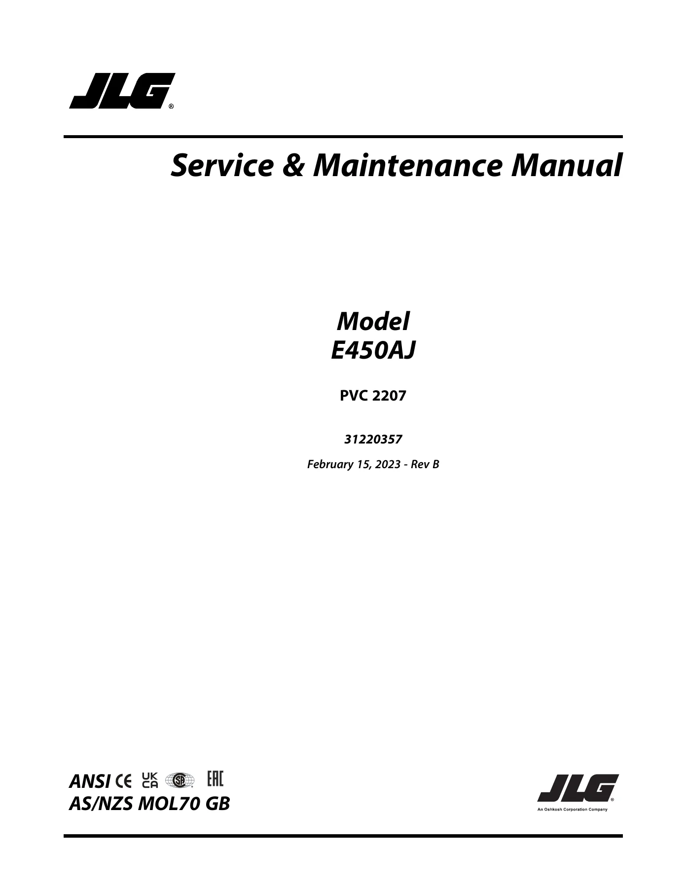
JLG E450AJ PVC 2207 Service and Maintenance Manual 2023 - PDF Download — PDF page 1 preview
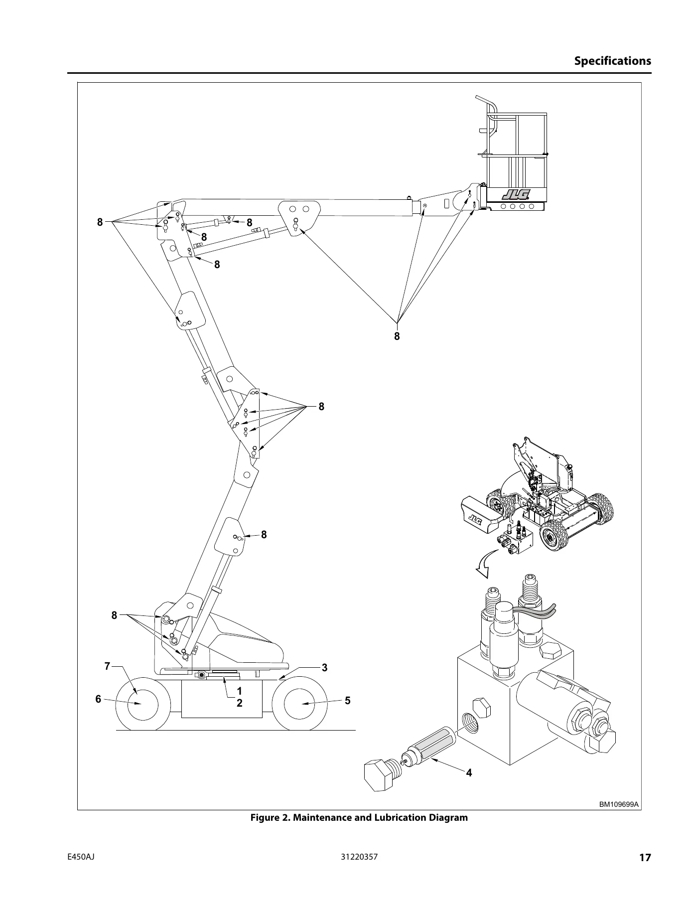
JLG E450AJ PVC 2207 Service and Maintenance Manual 2023 - PDF Download — PDF page 17 preview
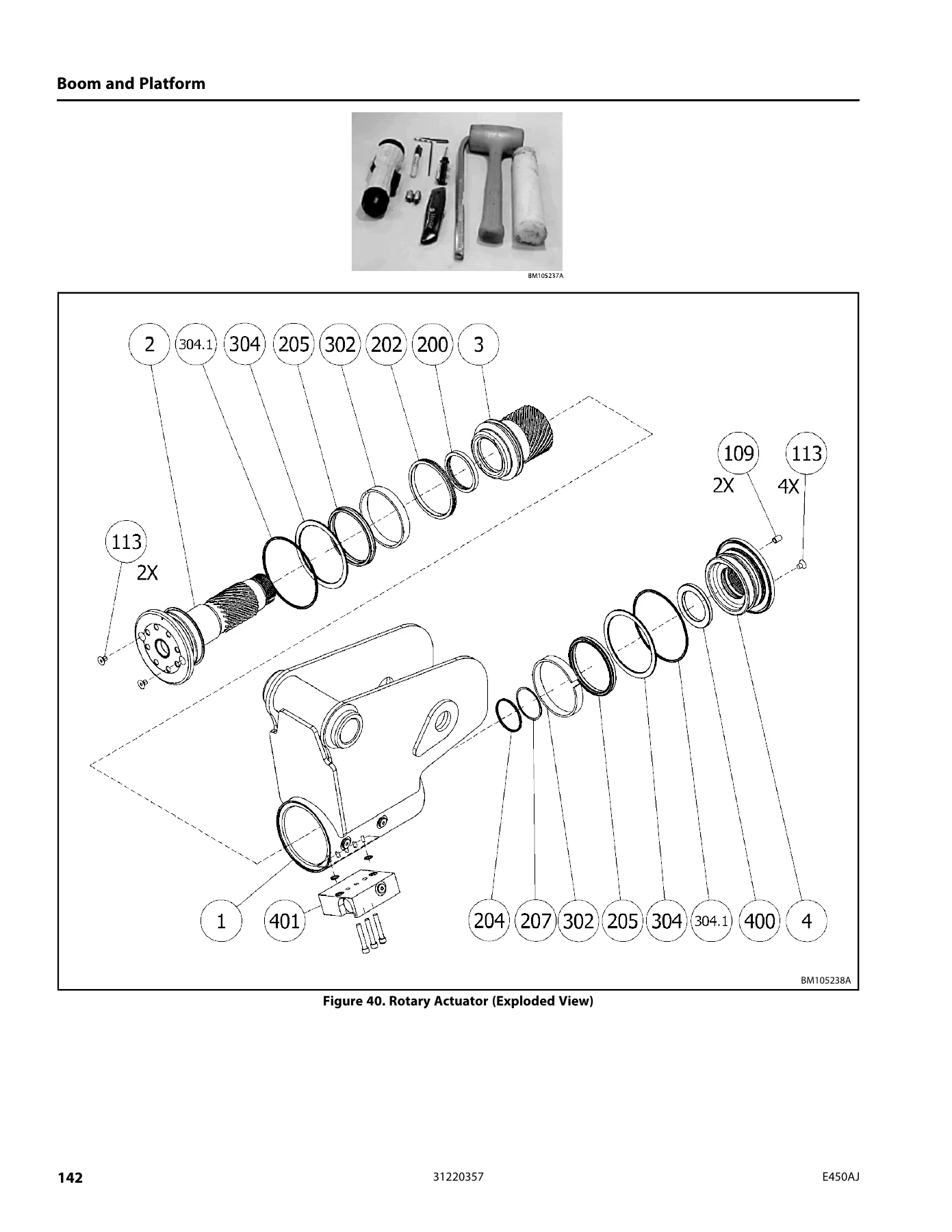
JLG E450AJ PVC 2207 Service and Maintenance Manual 2023 - PDF Download — PDF page 142 preview

  • Section 1: Specifications – Operating specifications, tire data, capacities, dimensional data, torque specifications, lubrication specifications, critical stability weights, major component weights, serial number locations, battery charger specifications, maintenance and lubrication schedule, threadlocking compound, and complete SAE and metric torque charts.
  • Section 2: General – Machine preparation, inspection, and maintenance requirements; service and guidelines; lubrication and information; cylinder drift theory and testing; pins and composite bearing repair guidelines; welding on JLG equipment.
  • Section 3: Chassis and Turntable – Tires and wheels, spindle assembly and wheel bearing end play, tilt module, speed sensor, drive hub roll and leak testing plus full disassembly and assembly, drive motor removal and rebuild, swing bearing inspection and replacement, swing motor troubleshooting and rebuild, battery maintenance and charging, Delta-Q battery charger operation and fault codes, supplementary fuse for APU, counterweight.
  • Section 4: Boom and Platform – Platform support removal and installation, rotator and platform level cylinder removal, main boom powertrack, boom maintenance and disassembly, wear pads, boom cleanliness guidelines, boom limit switches, articulating jib boom, boom synchronizing procedure, foot switch adjustment, rotary actuator theory and full rebuild, powertrack link and bracket replacement, SkyGuard operation and diagnostics, bolt-on external fall arrest system.
  • Section 5: Basic Hydraulic Information and Schematics – Lubricating O-rings in the hydraulic system, hydraulic connection assembly and torque specifications for NPTF, BSPT, JIC, SAE, ORFS, MBTL/MBTS, ORB, MPP, MFF, BSPP, and flange connections, hydraulic cylinder rebuild procedures for platform level, jib lift, lower lift, mid lift, upper lift, master, steer, and telescope cylinders, cylinder removal and installation, lower lift cylinder bleeding, pressure setting procedures, and hydraulic schematic.
  • Section 6: JLG Control System – Analyzer kit instructions, machine configuration programming, personality settings, machine orientation for testing, function speed specifications, calibrating steer, calibrating tilt sensor, calibrating load sensing, Load Sensing System (LSS) theory and diagnostics, resetting the MSSO system, drive cutout override service mode, and a complete Diagnostic Trouble Code (DTC) table.
  • Section 7: Basic Electrical Information and Schematics – Multimeter basics, checking switches, applying silicone dielectric compound, AMP and DEUTSCH connector assembly and disassembly, wiring harness connector labels, and full electrical schematics for the platform console, LSS, main valve, turntable, ground control panel, chassis traction, chassis steer/brake, head/tail light, inverter, generator, SkyGuard, Soft Touch, and charger harnesses.

This JLG E450AJ service manual is a comprehensive workshop document. It goes far beyond routine maintenance – it includes complete teardown and rebuild procedures for the drive hub, drive motor, swing motor, rotary actuator, and every hydraulic cylinder on the machine. It provides the hydraulic and electrical schematics needed to trace circuits and diagnose faults, and it documents the JLG control system analyzer menus, fault codes, and calibration procedures in full detail. For anyone responsible for the repair or maintenance of an E450AJ, this manual is the definitive reference.

What This Manual Enables You to Do

With this JLG E450AJ PVC 2207 service manual, you can perform the full range of maintenance and repair tasks on the machine:

Complete PDF Bookmark Tree

Complete Bookmarks

The complete bookmarks in the “JLG E450AJ PVC 2207 Service and Maintenance Manual 2023 – PDF Download” are as follows:

31220357_B_E450AJ_JLG_Service_Englishp. 1
Introduction – Maintenance Safety Precautions (task)p. 3
Revision Logp. 5
Table of Contentsp. 7
Specificationsp. 11
Operating Specifications (reference)p. 11
1.1.1 Machine Specificationsp. 11
Tires (reference)p. 11
Capacities (reference)p. 12
Dimensional Data (reference)p. 12
Torque Specifications (reference)p. 12
Lubrication Specifications (reference)p. 13
1.6.1 Hydraulic Oilp. 13
Critical Stability Weights (reference)p. 14
Major Component Weights (reference)p. 15
Serial Number Locations (reference)p. 15
Battery Charger Specifications (reference)p. 16
Maintenance and Lubrication (task)p. 18
Threadlocking Compound (reference)p. 21
Torque Charts (reference)p. 22
1.13.1 SAE Fastener Torque Chartp. 22
1.13.2 Metric Fastener Torque Chartp. 34
Generalp. 39
Machine Preparation, Inspection, and Maintenance (reference)p. 39
2.1.1 Generalp. 39
2.1.2 Preparation, Inspection, and Maintenancep. 39
2.1.3 Pre-Start Inspectionp. 39
2.1.4 Pre-Delivery Inspection and Frequent Inspectionp. 39
2.1.5 Annual Machine Inspectionp. 39
2.1.6 Preventative Maintenancep. 40
Service and Guidelines (task)p. 40
2.2.1 Generalp. 40
2.2.2 Safety and Workmanshipp. 40
2.2.3 Cleanlinessp. 40
2.2.4 Components Removal and Installationp. 40
2.2.5 Component Disassembly and Reassemblyp. 41
2.2.6 Pressure-Fit Partsp. 41
2.2.7 Bearingsp. 41
2.2.8 Gasketsp. 41
2.2.9 Bolt Usage and Torque Applicationp. 41
2.2.10 Hydraulic Lines and Electrical Wiringp. 41
2.2.11 Hydraulic Systemp. 41
2.2.12 Lubricationp. 42
2.2.13 Batteryp. 42
2.2.14 Lubrication and Servicingp. 42
Lubrication and Information (task)p. 42
2.3.1 Hydraulic Systemp. 42
2.3.2 Hydraulic Oilp. 42
2.3.3 Changing Hydraulic Oilp. 42
2.3.4 Lubrication Specificationsp. 43
Cylinder Drift (reference)p. 43
2.4.1 Theoryp. 43
2.4.2 Cylinder Leakage Testp. 43
2.4.3 Cylinder Thermal Driftp. 44
Pins and Composite Bearing Repair Guidelines (task)p. 44
Welding on JLG Equipment (reference)p. 44
2.6.1 Do the Following When Welding on JLG Equipmentp. 44
2.6.2 Do Not Do The Following When Welding On JLG Equipmentp. 44
Chassis and Turntablep. 49
Tires and Wheels (task)p. 49
3.1.1 Tire Damagep. 49
3.1.2 Tire Replacementp. 49
3.1.3 Wheel Replacementp. 49
3.1.4 Wheel Installationp. 49
Spindle (task)p. 50
3.2.1 Setting Wheel Bearing End Playp. 50
3.2.2 Specificationsp. 51
3.2.3 Checkingp. 51
3.2.4 Greasing Requirementsp. 51
Tilt Module (task)p. 54
Speed Sensor (reference)p. 55
Drive Hub (task)p. 62
3.5.1 Roll and Leak Testingp. 62
3.5.2 Tightening and Torquing Boltsp. 62
3.5.3 Main Disassemblyp. 63
3.5.4 Output Carrier Disassemblyp. 66
3.5.5 Input Carrier Disassemblyp. 67
3.5.6 Hub-spindle Disassemblyp. 68
3.5.7 Cover Disassemblyp. 69
3.5.8 Input Carrier Assemblyp. 70
3.5.9 Output Planet Gear Assemblyp. 71
3.5.10 Output Carrier Assemblyp. 71
3.5.11 Hub-spindle Assemblyp. 72
3.5.12 Cover Assemblyp. 72
3.5.13 Main Assemblyp. 73
Drive Motor (task)p. 75
3.6.1 Removalp. 75
3.6.2 Disassemblyp. 75
3.6.3 Inspectionp. 76
3.6.4 Assemblyp. 76
3.6.5 Installationp. 77
Swing Bearing (task)p. 79
3.7.1 Turntable Bearing Mounting Bolt Condition Checkp. 79
3.7.2 Wear Tolerancep. 81
3.7.3 Replacement of Swing Bearingp. 84
3.7.4 Swing Bearing Torque Valuep. 88
3.7.5 Checking Worm Gear End Playp. 88
3.7.6 Adjusting End Playp. 88
Swing Motor (task)p. 91
3.8.1 Preparation Before Disassemblyp. 94
3.8.2 Disassembly and Inspectionp. 95
3.8.3 Assemblyp. 103
3.8.4 One Piece Stator Constructionp. 112
3.8.5 Two Piece Stator Constructionp. 114
3.8.6 Final Checksp. 114
Battery Maintenance and Charging (task)p. 115
3.9.1 Battery Maintenance, Quarterlyp. 115
3.9.2 Battery Charging (On Board Charger)p. 115
Battery Charger (task)p. 116
3.10.1 Operating Instructionsp. 116
3.10.2 Maintenance Instructionsp. 117
3.10.3 Delta-Q – Battery Chargerp. 117
3.10.4 Battery Charger Fault Codesp. 117
3.10.5 Excessive Battery Watering Requirements or Strong Sulphur (Rotten Egg) Smellp. 121
3.10.6 Checking/Changing the Battery Charger Algorithmp. 121
Supplementary Fuse for APU (task)p. 122
3.11.1 Tools and Materialp. 122
3.11.2 Procedurep. 122
Counterweight (reference)p. 124
Boom and Platformp. 127
Platform (task)p. 127
4.1.1 Support Removalp. 127
4.1.2 Support Installationp. 128
Rotator And Platform Level Cylinder Removal (task)p. 130
4.2.1 Removalp. 130
4.2.2 Installationp. 131
Main Boom Powertrack (task)p. 131
4.3.1 Removalp. 131
4.3.2 Installationp. 132
Boom Maintenance (task)p. 133
4.4.1 Removalp. 133
4.4.2 Disassemblyp. 134
4.4.3 Inspectionp. 134
4.4.4 Assemblyp. 135
4.4.5 Installationp. 135
Wear Pads (task)p. 136
Boom Cleanliness Guidelines (task)p. 137
Boom Limit Switches (concept)p. 137
Articulating JIB Boom (task)p. 139
4.8.1 Removalp. 139
4.8.2 Disassemblyp. 139
4.8.3 Inspectionp. 139
4.8.4 Assemblyp. 140
Boom Synchronizing Procedure (task)p. 140
Foot Switch Adjustment (concept)p. 140
Rotary Actuator (task)p. 141
4.11.1 Theory of Operationp. 141
4.11.2 Tools Required for Assembly/Disassemblyp. 141
4.11.3 Disassemblyp. 145
4.11.4 Inspectionp. 151
4.11.5 Assemblyp. 152
4.11.6 Installing Counterbalance Valvep. 157
4.11.7 Greasing Thrust Washersp. 158
4.11.8 Testing the Actuatorp. 159
4.11.9 Installation and Bleedingp. 159
4.11.10 Troubleshootingp. 160
Powertrack Maintenance (task)p. 161
4.12.1 Removing a Linkp. 161
4.12.2 Installing a New Linkp. 168
4.12.3 Replacing Fixed End Bracketsp. 175
4.12.4 Replacing Moving End Bracketsp. 177
Skyguard (task)p. 180
4.13.1 Operationp. 180
4.13.2 Function Testp. 181
4.13.3 Diagnostics and Troubleshootingp. 182
Bolt-On External Fall Arrest (task)p. 183
4.14.1 Inspection Before Usep. 183
4.14.2 Installationp. 184
Basic Hydraulic Information and Schematicsp. 187
Lubricating O-Rings in the Hydraulic System (reference)p. 187
5.1.1 Cup and Brushp. 187
5.1.2 Dip Methodp. 188
5.1.3 Spray Methodp. 188
5.1.4 Brush-on Methodp. 189
Hydraulic Connection Assembly And Torque Specification (taskp. 189
5.2.1 Tapered Thread Typesp. 189
5.2.2 Straight Thread Types, Tube and Hose Connectionsp. 190
5.2.3 Straight Thread Types, Port Connectionsp. 191
5.2.4 Flange Connection Typesp. 191
5.2.5 Tightening Methodsp. 192
5.2.6 Assembly And Torque Specificationsp. 192
5.2.7 Assembly Instructions for American Standard Pipe Thread Tapered (NPTF) Connections.p. 193
5.2.8 Assembly Instructions for British Standard Pipe Thread Tapered (BSPT) Connectionsp. 194
5.2.9 Assembly Instructions for 37° (JIC) Flare Fittingsp. 195
5.2.10 Assembly Instructions for 45° SAE Flare Fittingsp. 197
5.2.11 Assembly Instructions for O-ring Face Seal (ORFS) Fittingsp. 199
5.2.12 Assembly Instructions for DIN 24° Flare Bite Type Fittings (MBTL and MBTS)p. 201
5.2.13 Assembly Instructions for Bulkhead (BH) Fittingsp. 203
5.2.14 Assembly Instructions for O-ring Boss (ORB) Fittingsp. 207
5.2.15 Assembly Instructions for Adjustable Port End Metric (MFF) Fittingsp. 219
5.2.16 Assembly Instructions for Metric ISO 6149 (MPP) Port Assembly Stud Endsp. 228
5.2.17 Assembly instructions for Adjustable Port End (BSPP) Fittingsp. 230
5.2.18 Assembly Instructions for Flange Connections: (FL61 and FL62)p. 243
5.2.19 Double Wrench Methodp. 247
5.2.20 FFWR and TFFT Methodsp. 247
5.2.21 Adjustable Stud End Assemblyp. 248
5.2.22 O-ring Installation (Replacement)p. 249
Hydraulic Cylinders (task)p. 249
5.3.1 Platform Level Cylinderp. 249
5.3.2 Jib Lift Cylinderp. 257
5.3.3 Lower Lift Cylinderp. 265
5.3.4 Mid Lift Cylinderp. 273
5.3.5 Upper Lift Cylinderp. 281
5.3.6 Master Cylinderp. 290
5.3.7 Steer Cylinderp. 298
5.3.8 Telescope Cylinderp. 307
Cylinder Removal And Installation (task)p. 316
5.4.1 Main Boom Lift Cylinder Removalp. 316
5.4.2 Main Boom Lift Cylinder Installationp. 316
5.4.3 Mid Boom Lift Cylinder Removalp. 317
5.4.4 Mid Boom Lift Cylinder Installationp. 317
5.4.5 Lower Boom Lift Cylinder Removalp. 318
5.4.6 Lower Boom Lift Cylinder Installationp. 318
5.4.7 Main Boom Telescope Cylinder Removalp. 318
5.4.8 Main Boom Telescope Cylinder Installationp. 319
Lower Lift Cylinder Bleeding Procedure (task)p. 320
Pressure Setting Procedures (task)p. 320
5.6.1 Main Reliefp. 320
5.6.2 Main Lift Down Reliefp. 320
5.6.3 Lower Lift Down Reliefp. 320
5.6.4 Telescope Reliefp. 320
5.6.5 Platform Level Up Reliefp. 321
5.6.6 Platform Level Down Reliefp. 321
5.6.7 Steer Reliefp. 322
5.6.8 Jib Lift (Up and Down) Reliefp. 322
5.6.9 Releveling Valve Reliefp. 322
Hydraulic Schematic (reference)p. 334
JLG Control Systemp. 339
JLG Control System Analyzer Kit Instructions (task)p. 339
6.1.1 Introductionp. 339
6.1.2 To Connect the JLG Control System Analyzerp. 340
6.1.3 Using the Analyzerp. 340
6.1.4 Changing the Access Level of the Hand Held Analyzerp. 342
6.1.5 Adjusting Parameters Using the Hand Held Analyzerp. 344
6.1.6 Machine Setupp. 344
6.1.7 Level Vehicle Descriptionp. 346
Machine Configuration Programming Information (reference)p. 349
Machine Personality Settings (reference)p. 356
Machine Orientation When Performing Test (task)p. 363
6.4.1 Test Notesp. 363
Function Speed (task)p. 364
6.5.1 Help Descriptions and Fault Flash Codesp. 387
6.5.2 Analyzer Diagnostics Menu Structurep. 393
6.5.3 System Self Testp. 398
Calibrating Steer (task)p. 404
Calibrating Tilt Sensor (task)p. 407
Calibrating Load Sensing (task)p. 410
Load Sensing System (LSS) (task)p. 413
6.9.1 Theory of Operationp. 413
6.9.2 Diagnostic Menup. 414
6.9.3 Calibration Procedurep. 415
6.9.4 LSS Testing and Evaluationp. 417
6.9.5 Troubleshootingp. 419
Resetting the MSSO System (task)p. 420
Drive Cutout Override Service Mode (task)p. 422
Basic Electrical Information and Schematicsp. 441
General (concept)p. 441
Multimeter Basics (reference)p. 441
7.2.1 Groundingp. 441
7.2.2 Backprobingp. 441
7.2.3 Min/Maxp. 441
7.2.4 Polarityp. 441
7.2.5 Scalep. 441
7.2.6 Voltage Measurementp. 442
7.2.7 Resistance Measurementp. 442
7.2.8 Continuity Measurementp. 443
7.2.9 Current Measurementp. 443
Checking Switches (task)p. 444
7.3.1 Basic Checkp. 444
7.3.2 Limit Switchesp. 444
7.3.3 Automatic Switchesp. 444
7.3.4 Switch Wiring – Low Side, High Sidep. 445
Applying Silicone Dielectric Compound to Electrical Connectip. 445
Dielectric Grease Application (reference)p. 446
7.5.1 Installationp. 446
7.5.2 AMP Mate-N-Lokp. 446
7.5.3 AMP Fastonp. 446
7.5.4 AMP Micro-Fitp. 446
7.5.5 AMP Mini Fit Jrp. 447
7.5.6 Mini Fit Srp. 447
7.5.7 DIN Connectorsp. 447
7.5.8 Exceptionsp. 447
AMP Connector (task)p. 447
7.6.1 Applying Silicone Dielectric Compound to AMP Connectorsp. 447
7.6.2 Assemblyp. 448
7.6.3 Disassemblyp. 450
7.6.4 Wedge Lockp. 451
7.6.5 Service – Voltage Readingp. 451
DEUTSCH Connectors (task)p. 452
7.7.1 DT/DTP Series Assemblyp. 452
7.7.2 DT/DTP Series Disassemblyp. 452
7.7.3 HD30/HDP20 Series Assemblyp. 453
7.7.4 HD30/HDP20 Series Disassemblyp. 453
Wiring Harness Connector Labels (reference)p. 454
7.8.1 Connector Labelsp. 454
7.8.2 Component Labelsp. 454
Electrical Schematics (concept)p. 541

  • Carry out scheduled lubrication and maintenance at the correct intervals with the right lubricants and capacities.
  • Diagnose and repair hydraulic system faults using the hydraulic schematic and pressure setting procedures.
  • Rebuild hydraulic cylinders – platform level, jib lift, lower lift, mid lift, upper lift, master, steer, and telescope – with correct seal installation and torque values.
  • Service the swing bearing, swing motor, drive hub, and drive motor with complete disassembly and assembly instructions.
  • Troubleshoot the JLG control system using the analyzer, interpret fault codes, and perform calibrations for steer, tilt sensor, and load sensing.
  • Trace electrical faults using the full electrical schematics for every harness on the machine.
  • Service the rotary actuator and powertrack with detailed rebuild and link replacement procedures.
  • Inspect and maintain the SkyGuard and bolt-on external fall arrest systems.

Why This Manual Matters

Working on an aerial work platform without the correct procedures and specifications is dangerous and can lead to component damage, machine instability, or personal injury. The JLG E450AJ service manual provides the exact torque values, pressure settings, wear limits, and adjustment procedures that JLG specifies for this model. It also includes the safety precautions that must be observed during maintenance – from relieving hydraulic system pressure before disconnecting lines to properly supporting the boom before working under it. Having the correct information at hand helps you get the job done right the first time and helps ensure the machine remains safe to operate.

Instant PDF Delivery

This JLG E450AJ PVC 2207 Service and Maintenance Manual is delivered as a PDF download immediately after payment. There is no shipping, no waiting for a physical book, and no risk of a lost or damaged package. You can access the manual on any device – computer, tablet, or smartphone – and print the pages you need for the shop. Whether you are a professional technician, a fleet maintenance manager, or an owner-operator, this manual gives you the complete service and maintenance information for the E450AJ in a convenient, searchable PDF format.
Reviews

There are no reviews yet.

Be the first to review “JLG E450AJ PVC 2207 Service and Maintenance Manual 2023 – PDF Download”

What Our Customers Say

★★★★★ Live reviews from customers
Loading customer reviews...
0
    0
    Your Cart
    Your cart is emptyReturn to Shop
    🛒
    Recently Purchased
    🕒 verified order