
Kubota 05 Series Diesel Engines Workshop Manual Multilingual – D905-B D1005-B V1205-B V1305-B D1105-B V1505-B Service Repair PDF
Original price was: $44.95.$29.95Current price is: $29.95.
Kubota 05 Series Diesel Engines Workshop Manual covering D905-B, D1005-B, V1205-B, V1205-T-B, V1305-B, D1105-B, D1105-T-B, V1505-B, and V1505-T-B models. Multilingual (English, French, German) 278-page PDF with mechanism, disassembly, servicing, specifications, troubleshooting, and maintenance procedures.
Description
Kubota 05 Series Diesel Engines Workshop Manual
This multilingual workshop manual provides complete service and repair coverage for Kubota 05 Series diesel engines, including the D905-B (E), D1005-B (E), V1205-B (E), V1205-T-B (E), V1305-B (E), D1105-B (E), D1105-T-B (E), V1505-B (E), and V1505-T-B (E) models. Published by Kubota Corporation in May 1996, this 278-page PDF is divided into two main parts: Mechanism, which explains the construction and function of each engine system, and Disassembling and Servicing, which provides the step-by-step procedures, factory specifications, and allowable limits technicians need for maintenance, troubleshooting, and overhaul.
File Details
- Manual Type: Workshop Manual (Mechanism & Disassembling/Servicing)
- Brand: Kubota
- Models Covered: D905-B (E), D1005-B (E), V1205-B (E), V1205-T-B (E), V1305-B (E), D1105-B (E), D1105-T-B (E), V1505-B (E), V1505-T-B (E)
- Engine Type: Vertical, water-cooled, 4-cycle diesel
- Language: English, French, German
- Page Count: 278 pages
- File Format: PDF
- Document Number: 97897-01643
- Publication Date: May 1996
- Publisher: Kubota Corporation
Chapters Covered
This Kubota 05 Series workshop manual organizes its content into the following major chapters, each with a Mechanism section and a Disassembling and Servicing section.
- Engine Body
- Lubricating System
- Cooling System
- Intake / Exhaust System
- Fuel System
- Electrical System
- Turbo Charger System
Engine Body
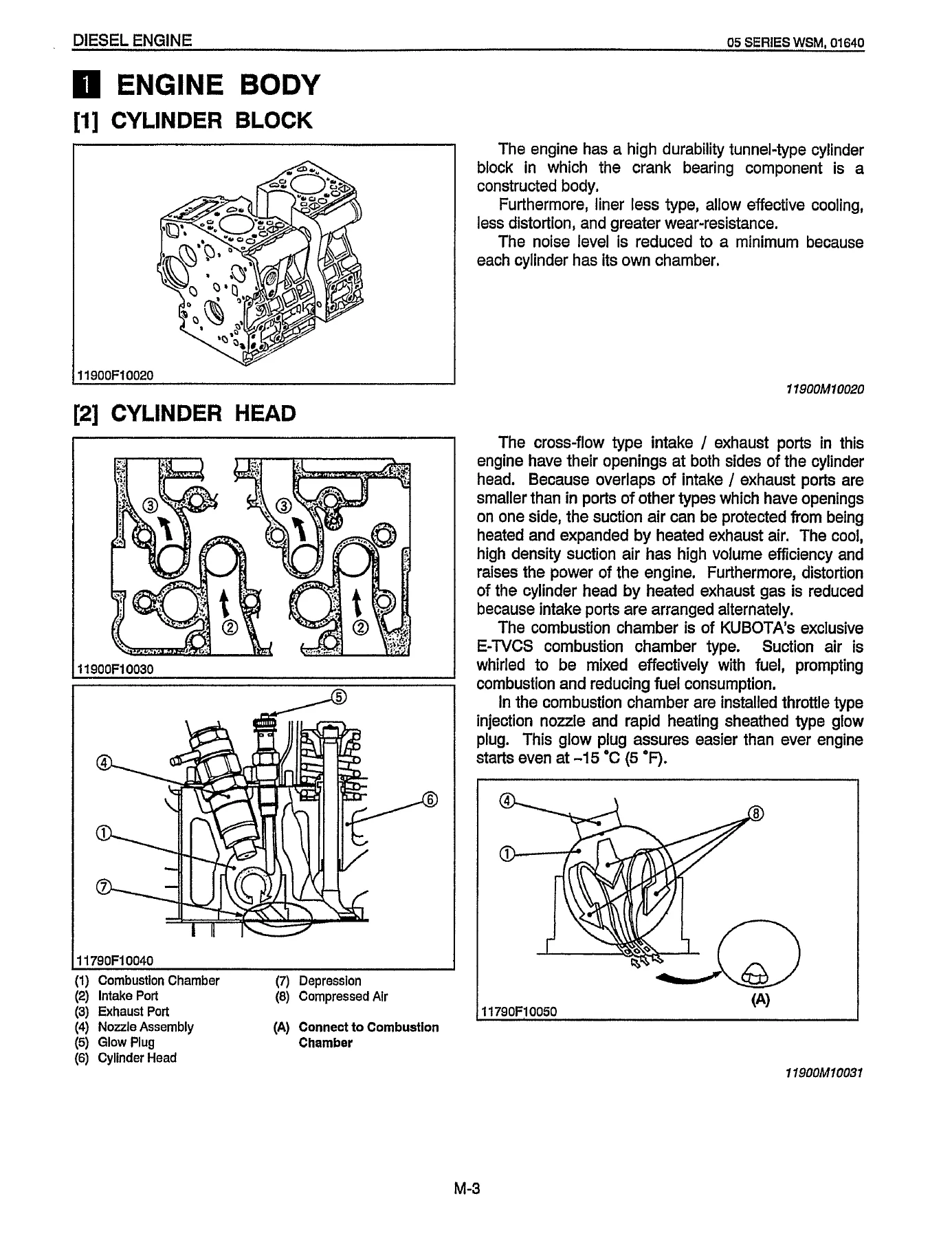
The engine body chapter covers the cylinder block, cylinder head, crankshaft, piston and piston rings, connecting rod, rocker arm, camshaft, fuel camshaft, and flywheel. It explains the tunnel-type cylinder block with integrated crank bearing supports, the cross-flow intake and exhaust ports that reduce intake air heating, and the E-TVCS (Three Vortex Combustion System) combustion chamber used in engines built from January 1994 onward. The servicing portion includes checking and adjustment procedures for cylinder head flatness, top clearance, compression pressure, valve clearance, valve timing, valve spring free length and tilt, rocker arm shaft clearance, tappet clearance, camshaft side clearance and cam height, timing gear backlash, piston ring gap and groove clearance, connecting rod alignment, crankshaft alignment and oil clearances, and cylinder liner wear limits.
Lubricating System
This chapter details the trochoid oil pump, relief valve, oil filter cartridge, and oil pressure switch. The mechanism section traces the oil path from the oil strainer through the pump and filter to the crankshaft, connecting rods, idle gear, governor shaft, camshaft, and rocker arm shaft, with splash lubrication reaching the pistons, cylinders, small ends, tappets, push rods, and valves. Servicing content includes oil pressure testing at idle and rated speeds, rotor lobe clearance and end clearance measurement, and oil filter cartridge replacement with the bypass valve function explained.
Cooling System
The cooling system chapter covers the centrifugal water pump, wax-pellet thermostat, radiator, and radiator cap. It explains the pressurized cooling circuit, thermostat opening at approximately 71°C (160°F), and the function of the radiator cap in maintaining system pressure at 88 kPa (0.9 kgf/cm²). Servicing sections include fan belt tension and damage checks, thermostat opening temperature verification, radiator water tightness testing at 137 kPa, and radiator cap air leakage testing.
Intake / Exhaust System
Covers the dry-cyclone air cleaner and muffler. The air cleaner uses a fin to create a whirling airflow that separates heavier dust particles into the dust cup, while finer dust is trapped by the element. The muffler uses a perforated inner and outer tube with glass wool to absorb high-frequency exhaust noise. Maintenance instructions for cleaning the air filter element and dust cup are included.
Fuel System
This chapter covers the Bosch MD type mini injection pump, injection nozzle, fuel filter, mechanical governor, and automatic advance timer. The mechanism section explains the pump element and plunger operation, delivery valve reverse-flow prevention and suck-back functions, dumping valve, injection control via the control rack, and the centrifugal mechanical governor that maintains engine speed under fluctuating loads. Servicing content includes injection timing adjustment with shims, fuel tightness testing of the pump element and delivery valve, injection nozzle pressure testing and adjustment with washers, and fuel filter cleaning procedures.
Electrical System
The electrical system chapter covers the charging system, including the compact alternator with integrated IC regulator. It explains the alternator’s construction, the IC regulator’s solid-state control of field current and charge lamp operation, and the charging circuit. Servicing sections include starter motor testing, magnet switch testing, glow plug resistance checks, alternator disassembly and assembly, and IC regulator and rectifier testing.
Turbo Charger System
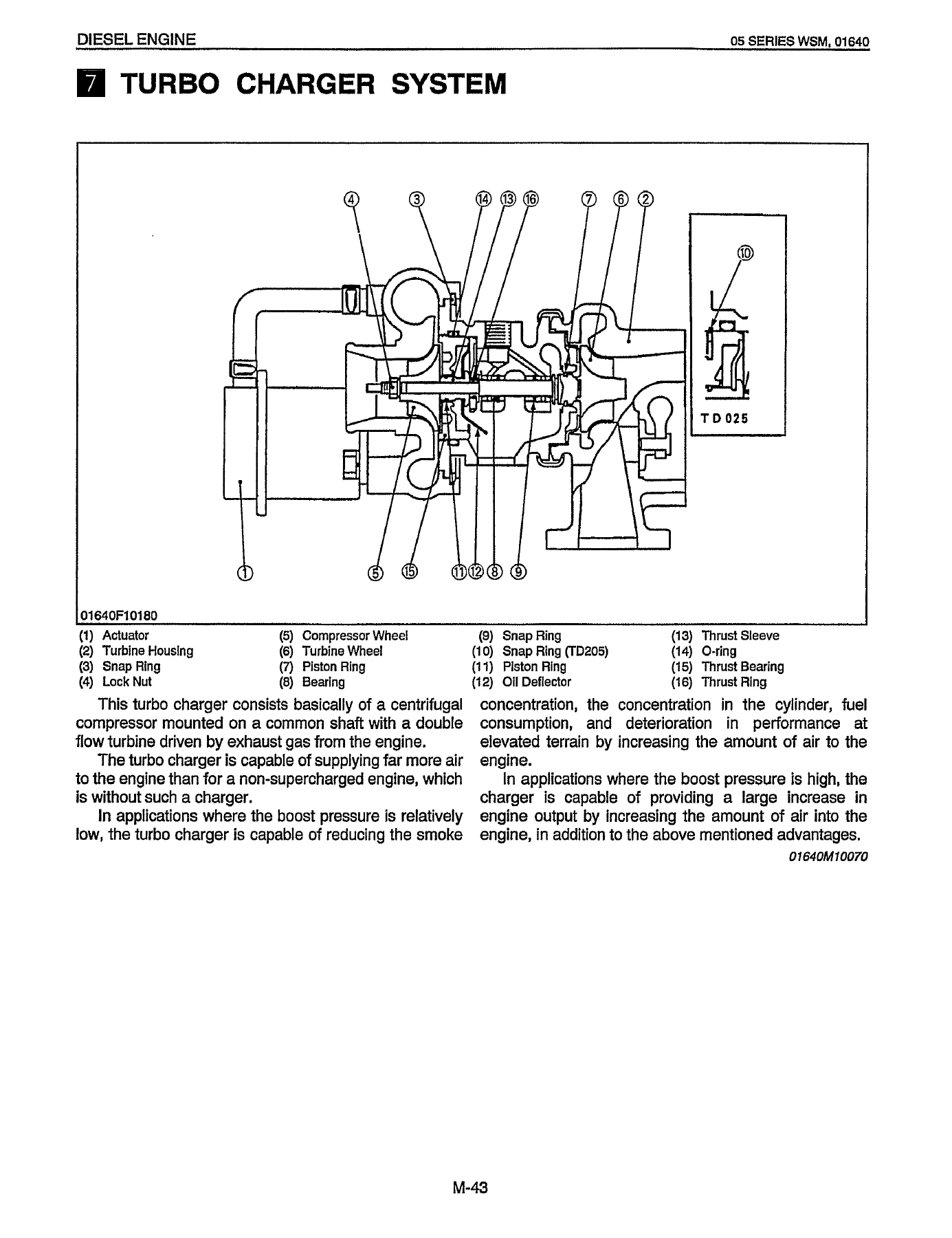
For turbocharged models, this chapter details the turbocharger’s centrifugal compressor, double-flow turbine, floating metal bearings, and piston ring seals. The mechanism section explains how exhaust gas energy drives the turbine wheel, which rotates the compressor wheel on the same shaft to compress intake air and increase cylinder charge density. Servicing includes axial and radial clearance checks, wheel shaft inspection, and turbocharger disassembly and assembly with torque values.
General Information, Troubleshooting, and Specifications
The General section includes engine identification by model name and serial number, cylinder numbering, general precautions for disassembly and reassembly, tightening torques for special and general-use screws, bolts, and nuts, a detailed troubleshooting table covering symptoms such as engine not starting, starter not running, uneven engine revolution, white or blue exhaust gas, black or dark gray exhaust gas, deficient output, excessive lubricant oil consumption, fuel mixed into lubricant oil, water mixed into lubricant oil, low oil pressure, high oil pressure, engine overheated, and battery quickly discharging. It also includes servicing specifications for the engine body, lubricating system, cooling system, fuel system, and electrical system, a maintenance check list with intervals at 50, 100, 800, and 1500 hours, and special tools with their application and code numbers.
Disassembling and Servicing Procedures
Each engine system chapter includes a dedicated Disassembling and Servicing section with step-by-step procedures, precautions, and factory specifications. These sections cover draining water and oil, external component removal, cylinder head and valve service, gear case disassembly, piston and connecting rod removal, flywheel and crankshaft service, and the reassembly procedures with torque values, alignment marks, and sealant application instructions. The manual also notes the engine serial number break at 489290 and 489291 for the combustion chamber type and the corresponding cylinder head configuration change with the nozzle heat seal.
Why This Kubota 05 Series Workshop Manual Matters
Whether you are diagnosing a no-start condition, adjusting valve clearance, replacing a head gasket, rebuilding the injection pump, servicing the turbocharger, or performing a complete engine overhaul, this workshop manual gives you the exact procedures and specifications that Kubota technicians use. The clean exhaust engine [E] designation and the serial number break points are clearly noted, so you can identify which procedures apply to your specific engine. The multilingual format — English, French, and German — makes it usable across regions and languages.
With instant PDF delivery after payment, no shipping delays, and the ability to view it on any device or print the pages you need for the workshop, this Kubota 05 Series workshop manual is a practical, permanent reference for every service job on these D905-B, D1005-B, V1205-B, V1205-T-B, V1305-B, D1105-B, D1105-T-B, V1505-B, and V1505-T-B diesel engines.
IMAGES PREVIEW
Reviews
There are no reviews yet.